1997 SSANGYONG KORANDO engine
[x] Cancel search: enginePage 1465 of 2053
SSANGYONG MY2002
6B-4 POWER STEERING PUMP
KAA6B010
REPAIR INSTRUCTIONS
ON-VEHICLE SERVICE
SERPENTINE ACCESSORY DRIVE
BELT
Removal and Installation Procedure
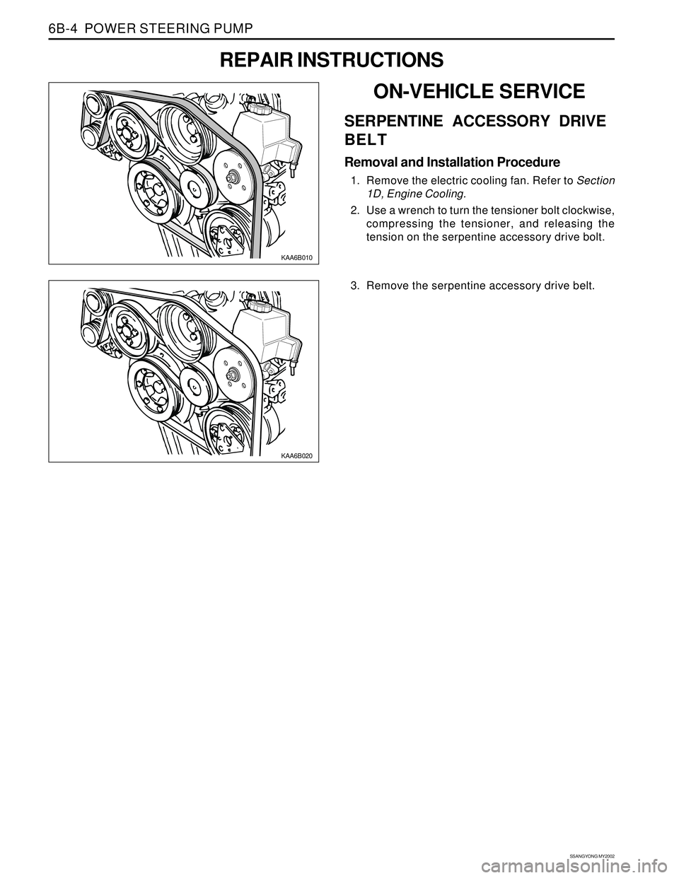
1. Remove the electric cooling fan. Refer to Section
1D, Engine Cooling.
2. Use a wrench to turn the tensioner bolt clockwise,
compressing the tensioner, and releasing the
tension on the serpentine accessory drive bolt.
KAA6B020
3. Remove the serpentine accessory drive belt.
Page 1466 of 2053
POWER STEERING PUMP 6B-5
SSANGYONG MY2002
KAA6B050
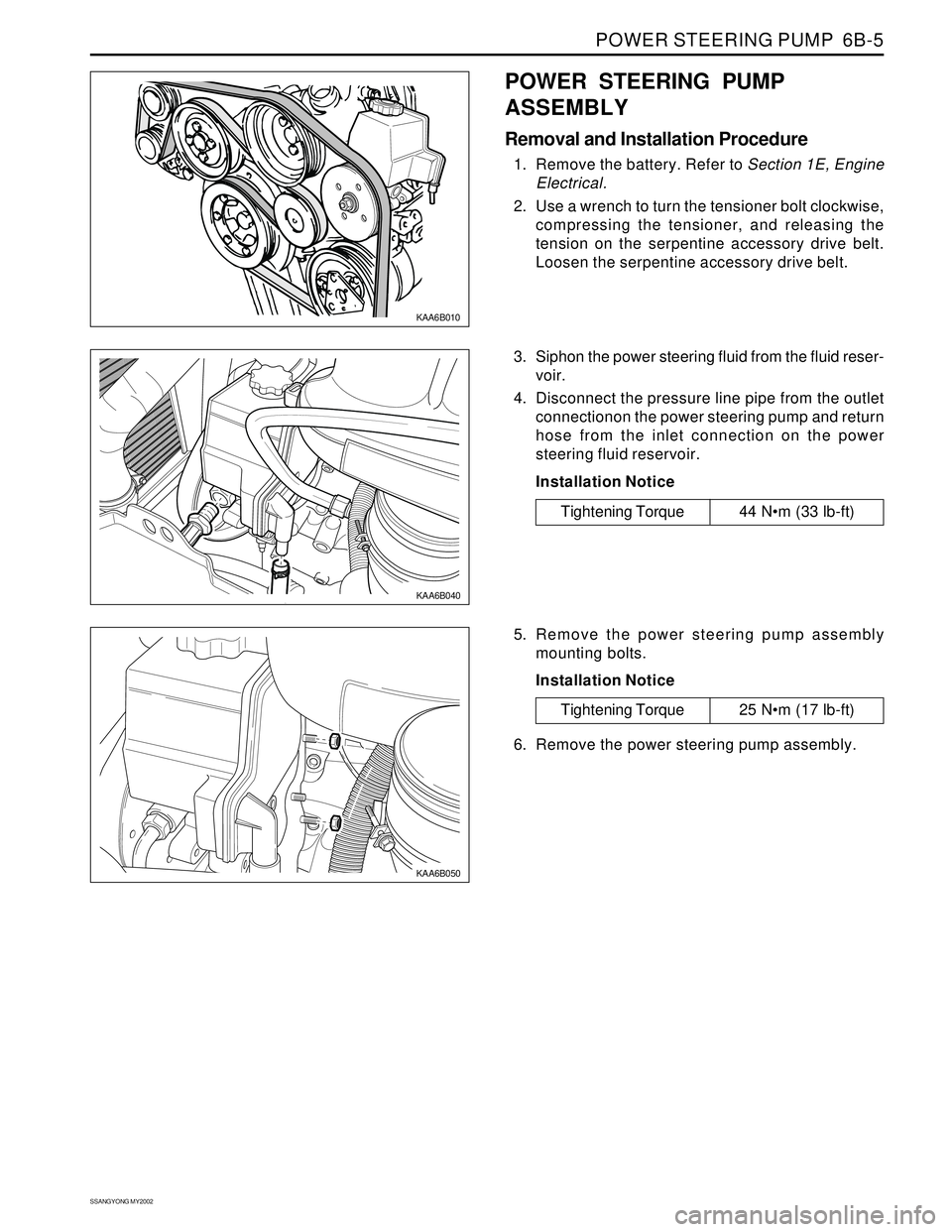
5. Remove the power steering pump assembly
mounting bolts.
Installation Notice
KAA6B040
3. Siphon the power steering fluid from the fluid reser-
voir.
4. Disconnect the pressure line pipe from the outlet
connectionon the power steering pump and return
hose from the inlet connection on the power
steering fluid reservoir.
Installation Notice
Tightening Torque 44 Nm (33 lb-ft)
KAA6B010
POWER STEERING PUMP
ASSEMBLY
Removal and Installation Procedure
1. Remove the battery. Refer to Section 1E, Engine
Electrical.
2. Use a wrench to turn the tensioner bolt clockwise,
compressing the tensioner, and releasing the
tension on the serpentine accessory drive belt.
Loosen the serpentine accessory drive belt.
Tightening Torque 25 Nm (17 lb-ft)
6. Remove the power steering pump assembly.
Page 1473 of 2053
POWER STEERING GEAR 6C-5
SSANGYONG MY2002
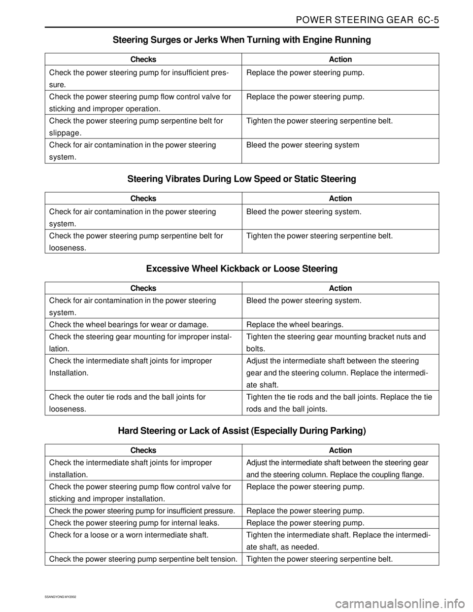
Check the power steering pump for insufficient pres-
sure.
Check the power steering pump flow control valve for
sticking and improper operation.
Check the power steering pump serpentine belt for
slippage.
Check for air contamination in the power steering
system.ChecksActionReplace the power steering pump.
Replace the power steering pump.
Tighten the power steering serpentine belt.
Bleed the power steering system
Steering Surges or Jerks When Turning with Engine Running
Check for air contamination in the power steering
system.
Check the power steering pump serpentine belt for
looseness.ChecksActionBleed the power steering system.
Tighten the power steering serpentine belt.
Steering Vibrates During Low Speed or Static Steering
Excessive Wheel Kickback or Loose Steering
Check for air contamination in the power steering
system.
Check the wheel bearings for wear or damage.
Check the steering gear mounting for improper instal-
lation.
Check the intermediate shaft joints for improper
Installation.
Check the outer tie rods and the ball joints for
looseness.ChecksActionBleed the power steering system.
Replace the wheel bearings.
Tighten the steering gear mounting bracket nuts and
bolts.
Adjust the intermediate shaft between the steering
gear and the steering column. Replace the intermedi-
ate shaft.
Tighten the tie rods and the ball joints. Replace the tie
rods and the ball joints.
Hard Steering or Lack of Assist (Especially During Parking)
Check the intermediate shaft joints for improper
installation.
Check the power steering pump flow control valve for
sticking and improper installation.
Check the power steering pump for insufficient pressure.
Check the power steering pump for internal leaks.
Check for a loose or a worn intermediate shaft.
Check the power steering pump serpentine belt tension.ChecksActionAdjust the intermediate shaft between the steering gear
and the steering column. Replace the coupling flange.
Replace the power steering pump.
Replace the power steering pump.
Replace the power steering pump.
Tighten the intermediate shaft. Replace the intermedi-
ate shaft, as needed.
Tighten the power steering serpentine belt.
Page 1474 of 2053
SSANGYONG MY2002
6C-6 POWER STEERING GEAR
POWER STEERING RACK AND
PINION GEAR BENCH TESTING
Removal and Installation Procedure
Notice: Pressure checks or pressure and flow checks
may also be conducted using this setup.
1. Disconnect and remove the power steering gear.
Refer to “Rack and Pinion Assembly” in this
section.
2. Place the power steering gear on a bench next to
the vehicle.
3. Disconnect the pressure line at the point where the
hose connects to the pipe. Extend this line to reach
the power steering gear on the bench.
4. Disconnect the return line from the power steering
fluid reservoir. Extend this line to reach the power
steering gear on the bench.
5. Connect the power steering pipes to the power
steering gear.
6. Start the engine and allow it to idle for 10 seconds.
7. Check the power steering fluid level. Refer to
Section 6A, Power Steering System.
8. Start the engine and turn the rack and pinion stub
shaft a full turn in each direction. Hold the shaft
against each stop for 5 seconds.
9. Inspect for possible leak points. Refer to Section
6A, Power Steering System.
Installation Procedure
1. Stop the engine.
2. Disconnect the power steering pipes from the power
steering gear.
KAA6C020
3. Remove the extensions and reconnect the pressure
and return lines.
4. Install and connect the power steering gear. Refer
to “Rack and Pinion Assembly” in this section.
5. Start the engine and allow it to idle for 10 seconds.
6. Check the power steering fluid level. Refer to
Section 6A, Power Steering System.
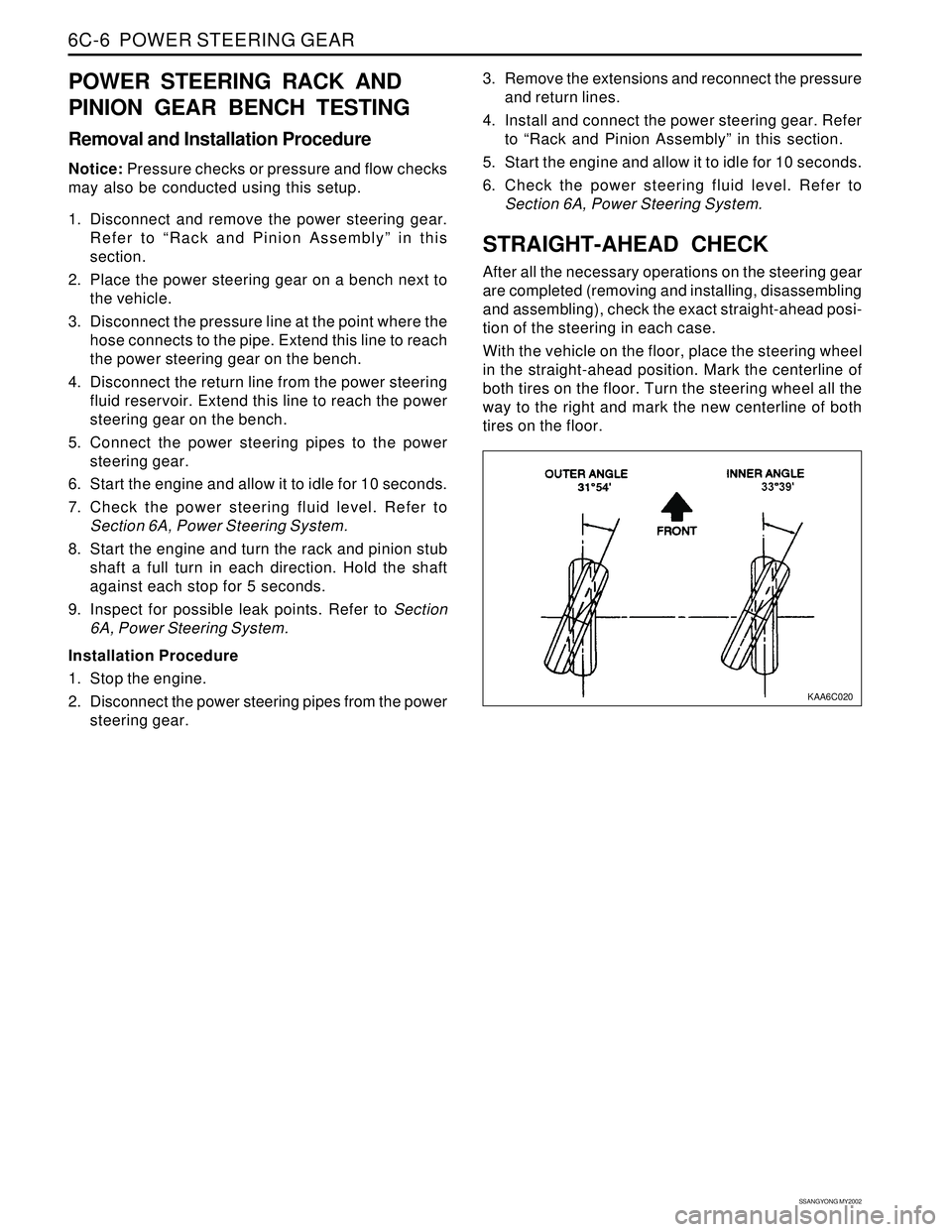
STRAIGHT-AHEAD CHECK
After all the necessary operations on the steering gear
are completed (removing and installing, disassembling
and assembling), check the exact straight-ahead posi-
tion of the steering in each case.
With the vehicle on the floor, place the steering wheel
in the straight-ahead position. Mark the centerline of
both tires on the floor. Turn the steering wheel all the
way to the right and mark the new centerline of both
tires on the floor.
Page 1490 of 2053
SSANGYONG MY2002
6E-4 POWER STEERING AND COLUMN
DIAGNOSTIC INFORMATION AND PROCEDURES
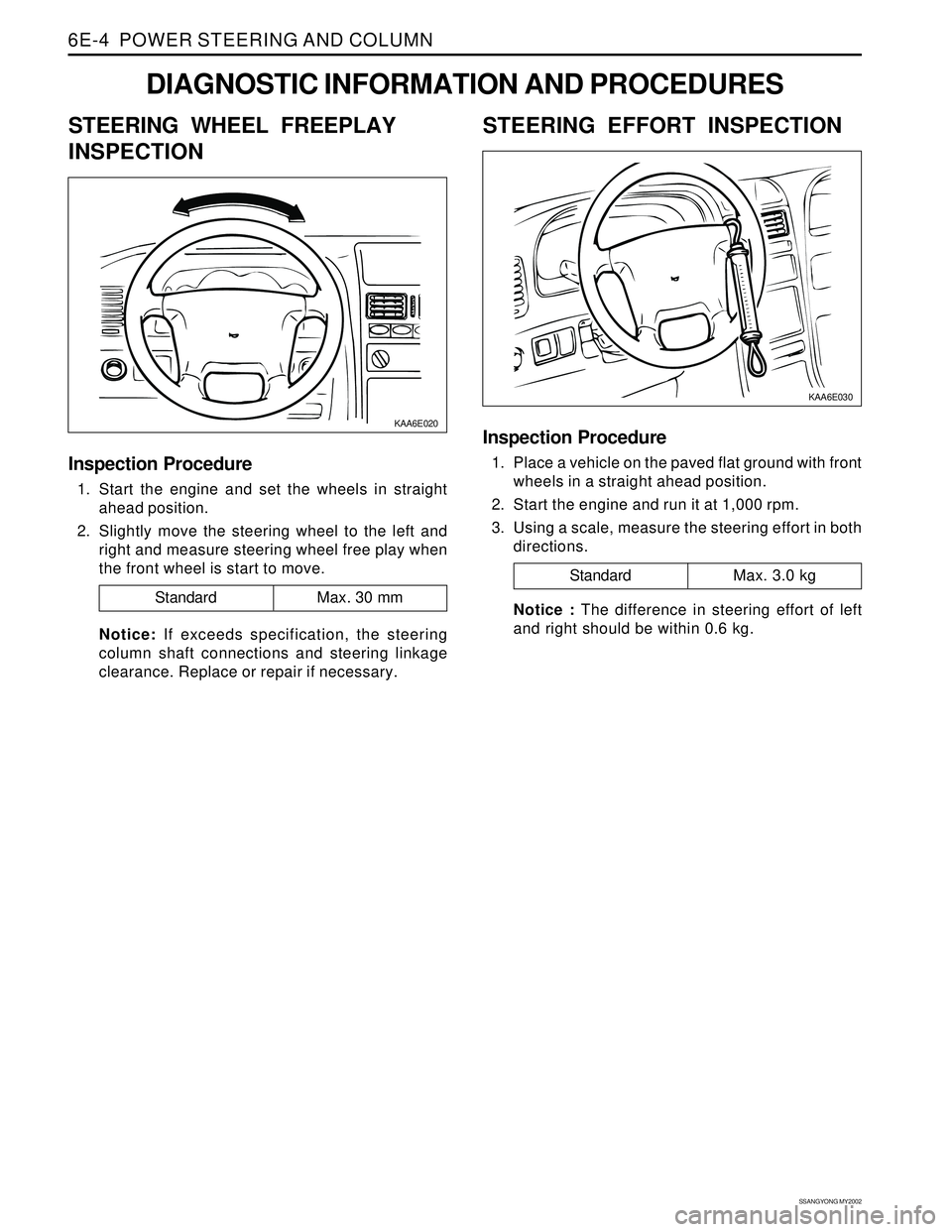
STEERING WHEEL FREEPLAY
INSPECTION
KAA6E020
Inspection Procedure
1. Start the engine and set the wheels in straight
ahead position.
2. Slightly move the steering wheel to the left and
right and measure steering wheel free play when
the front wheel is start to move.
Notice: If exceeds specification, the steering
column shaft connections and steering linkage
clearance. Replace or repair if necessary.
StandardMax. 30 mm
STEERING EFFORT INSPECTION
KAA6E030
Inspection Procedure
1. Place a vehicle on the paved flat ground with front
wheels in a straight ahead position.
2. Start the engine and run it at 1,000 rpm.
3. Using a scale, measure the steering effort in both
directions.
Notice : The difference in steering effort of left
and right should be within 0.6 kg.
StandardMax. 3.0 kg
Page 1502 of 2053
SECTION 7A
HEATING AND VENTILATION SYSTEM
CAUTION: The cooling system is pressurized when hot. Injury can result from removing the coolant reservoir
cap before the engine is sufficiently cool.
TABLE OF CONTENTS
Description and Operation ................................7A-2
Heating and Ventilation System .........................7A-2
Components Locator ..........................................7A-3
Heater System ...................................................7A-3
Diagnostic Information and Procedures ..........7A-4
Heater System ...................................................7A-4
Blower Electrical ................................................7A-8
Mode Controls Do Not Work .............................7A-10
Air Source Selection Not Controlled ..................7A-12
Temperature Controls Do Not Work ..................7A-13
Too Much Heat .................................................7A-14
Blower Noise ....................................................7A-16
Repair Instructions ............................................7A-18
On-Vehicle Service..............................................7A-18
Temperature Control Cable Adjustment ............7A-18
Controller Assembly and Temperature
Control Cable .................................................7A-18
Control Assembly Knob Lighting ......................7A-19Air Intake Door Actuator ...................................7A-19
Mode Control Door Actuator .............................7A-20
Heater/Air Distributor Case Assembly ..............7A-20
Blower Motor ....................................................7A-21
Blower Resistor ................................................7A-22
Blower Unit .......................................................7A-22
Heater Inlet Hose ..............................................7A-23
Heater Outlet Hose ...........................................7A-23
Heater Core......................................................7A-24
Rear Heater Duct ..............................................7A-24
Air Filter ............................................................7A-24
Specifications .................................................... 7A-25
Heater Temperature Specification .....................7A-25
Heater Unit .......................................................7A-25
Fastener Tightening Specification .....................7A-25
Schematic and Routing Diagrams ................... 7A-26
Non - A/C Wiring Diagram ................................7A-26
Airflow Through Vents .......................................7A-28
Page 1503 of 2053
SSANGYONG MY2002
7A-2 HEATING AND VENTILATION SYSTEM
DESCRIPTION AND OPERATION
HEATING AND VENTILATION
SYSTEM
The base heater system is designed to provide heating,
ventilation, windshield defrosting, side wind defogging
and rear seat area.
The heater and fan assembly blower regulates the air-
flow from the air inlet for further processing and distribu-
tion.
The heater core transfers the heater from the engine
coolant to the inlet air.
The temperature door regulates the amount of the air
that passes through the heater core. The temperature
door also controls the temperature of the air by control-
ling mix of heated air with the ambient air.
The mode door regulates the flow and distribution of
the processed air to the heater ducts and to the defroster
ducts.
The console mounted heating and ventilation control
panel contains one rotary control knob, one sliding con-
trol lever and six push control knobs, which operate as
follows:
Sliding Temperature Control Lever
•Actuates by cable.
Raise the temperature of the air entering the vehicle
by sliding to the right, or the red portion of the knob.
Five Mode Control Knob
Actuates by electricity.
Regulates the air distribution between the
windshield, the instrument panel, and the floor
vents.
Rotary Blower Control Knob
Turns on to operate the blower motor at four speeds.
Turns OFF to stop the blower.
Operates completely independently from both the
mode control knob and temperature control knob.
Changes the fan speed in any mode and at any
speed.
Intake Air Control Knob
Operates by electricity.
Switches between recirculating the passenger
compartment air and bringing outside air into the
passenger compartment.
Is normally in fresh air mode.
Illuminates the indicator lamp when in the recalculat
ing mode.
Heater Core
The heater core heats the air before enters the vehicle.
Engine coolant is circulated through the core to heat
the outside air passing over the fins of the core. The
core is functional at all times and may be used to
temper conditioned air in the A/C mode as well as in
the heat or the vent mode.
Page 1505 of 2053
SSANGYONG MY2002
7A-4 HEATING AND VENTILATION SYSTEM
DIAGNOSTIC INFORMATION AND PROCEDURES
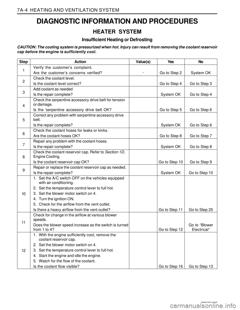
HEATER SYSTEM
Insufficient Heating or Defrosting
CAUTION: The cooling system is pressurized when hot. Injury can result from removing the coolant reservoir
cap before the engine is sufficiently cool.
Step
1
2
3
4
5
6
7
8
9
10
11
12
Action
Verify the customer’s complaint.
Are the customer’s concerns verified?
Check the coolant level.
Is the coolant level correct?
Add coolant as needed
Is the repair complete?
Check the serpentine accessory drive belt for tension
or damage.
Is the ’serpentine accessory drive belt OK?
Correct any problem with serpentine accessory drive
belt.
Is the repair complete?
Check the coolant hoses for leaks or kinks.
Are the coolant hoses OK?
Repair any problem with the coolant hoses.
Is the repair complete?
Check the coolant reservoir cap. Refer to Section 1D,
Engine Cooling.
Is the coolant reservoir cap OK?
Repair or replace the coolant reservoir cap as needed.
Is the repair complete?
1. Set the A/C switch OFF on the vehicles equipped
with air conditioning.
2. Set the temperature control lever to full hot.
3. Set the blower motor switch on 4.
4. Turn the ignition ON.
5. Check for the airflow from the vent outlet.
Is there a heavy airflow from the vent outlet?
Check for change in the airflow at various blower
speeds.
Does the blower speed increase as the switch is turned
from 1 to 4?
1. With the engine sufficiently cool, remove the
coolant reservoir cap.
2. Set the blower motor switch on 4.
3. Set the temperature control lever to full hot.
4. Start the engine and idle the engine.
5. Watch for the flow of the coolant.
Is the coolant flow visible?Yes
Go to Step 2
Go to Step 4
System OK
Go to Step 5
System OK
Go to Step 8
System OK
Go to Step 10
System OK
Go to Step 11
Go to Step 12
Go to Step 16No
System OK
Go to Step 3
Go to Step 4
Go to Step 6
Go to Step 6
Go to Step 7
Go to Step 8
Go to Step 9
Go to Step 10
Go to Step 25
Go to “Blower
Electrical”
Go to Step 13 Value(s)
-