Page 1330 of 2053
SSANGYONG MY2002
5B-22 MANUAL TRANSMISSION
62 - 93 Nm
(45 - 69 lb-ft)
21 - 35 Nm
(15 - 26 lb-ft)
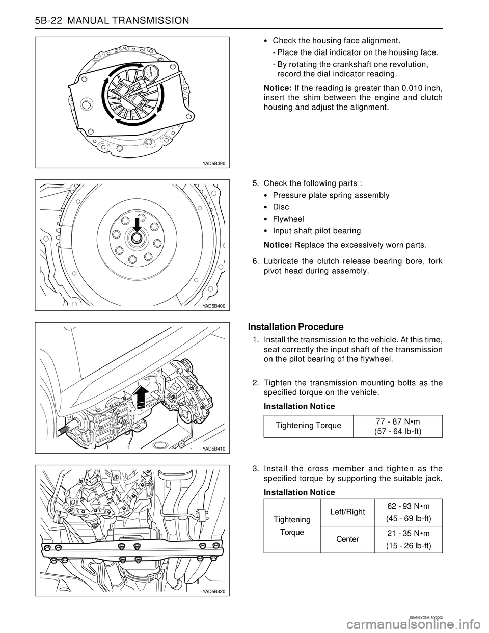
Check the housing face alignment.
- Place the dial indicator on the housing face.
- By rotating the crankshaft one revolution,
record the dial indicator reading.
Notice: If the reading is greater than 0.010 inch,
insert the shim between the engine and clutch
housing and adjust the alignment.
5. Check the following parts :
Pressure plate spring assembly
Disc
Flywheel
Input shaft pilot bearing
Notice: Replace the excessively worn parts.
6. Lubricate the clutch release bearing bore, fork
pivot head during assembly.
Installation Procedure
1. Install the transmission to the vehicle. At this time,
seat correctly the input shaft of the transmission
on the pilot bearing of the flywheel.
2. Tighten the transmission mounting bolts as the
specified torque on the vehicle.
Installation Notice
YAD5B390
YAD5B400
YAD5B410
YAD5B420
Tightening Torque77 - 87 Nm
(57 - 64 lb-ft)
3. Install the cross member and tighten as the
specified torque by supporting the suitable jack.
Installation Notice
Tightening
TorqueLeft/Right
Center
Page 1361 of 2053
SSAMGYONG MY2002
5C-6 CLUTCH
CLUTCH DISC
Preceding Work : Removal of the transmission
KAA5C040
1 Clutch Disc
2 Clutch Cover Assembly
3 Release Bearing
4 Clutch Housing5 Washer
6 Bolt........................................... 23 Nm (17 lb-ft)
7 Washer
8 Bolt........................................... 54 Nm (40 lb-ft)
Tools
602 589 00 40 00 Engine Lock
661 589 00 15 00 Centering Pin
Page 1362 of 2053
CLUTCH 5C-7
SSANGYONG MY2002
Removal & Installation Procedure
Tools Required
602589 00 40 00 Engine Lock
1. Remove the starter motor. Install the special tool
to the flywheel through the starter motor mounting
holes.
2. Unscren the release cylinder mounting bolts and
remove the release cylinder.
Installation Notice
3. Unscrew the clutch housing bolts and remove the
clutch housing, release fork and release bearing.
Installation Notice
4. Insert the centering pin into the clutch spline.
Loosen the clutch cover bolts 1/2 turn in crisscross
sequence until the spring tension is released.
Notice: Do not remove the bolts at a time, or
clutchcover can be damaged or deformed.
Tools Required
Centering Pin 661 589 00 15 00
KAA5C050
KAA5C060
KAA5C070
KAA5C080
Tightening Torque15 - 18 Nm
(11 - 13 lb-ft)
Tightening Torque 54 Nm (40 lb-ft)
Page 1369 of 2053
CLUTCH 5C-15
SSANGYONG MY2002
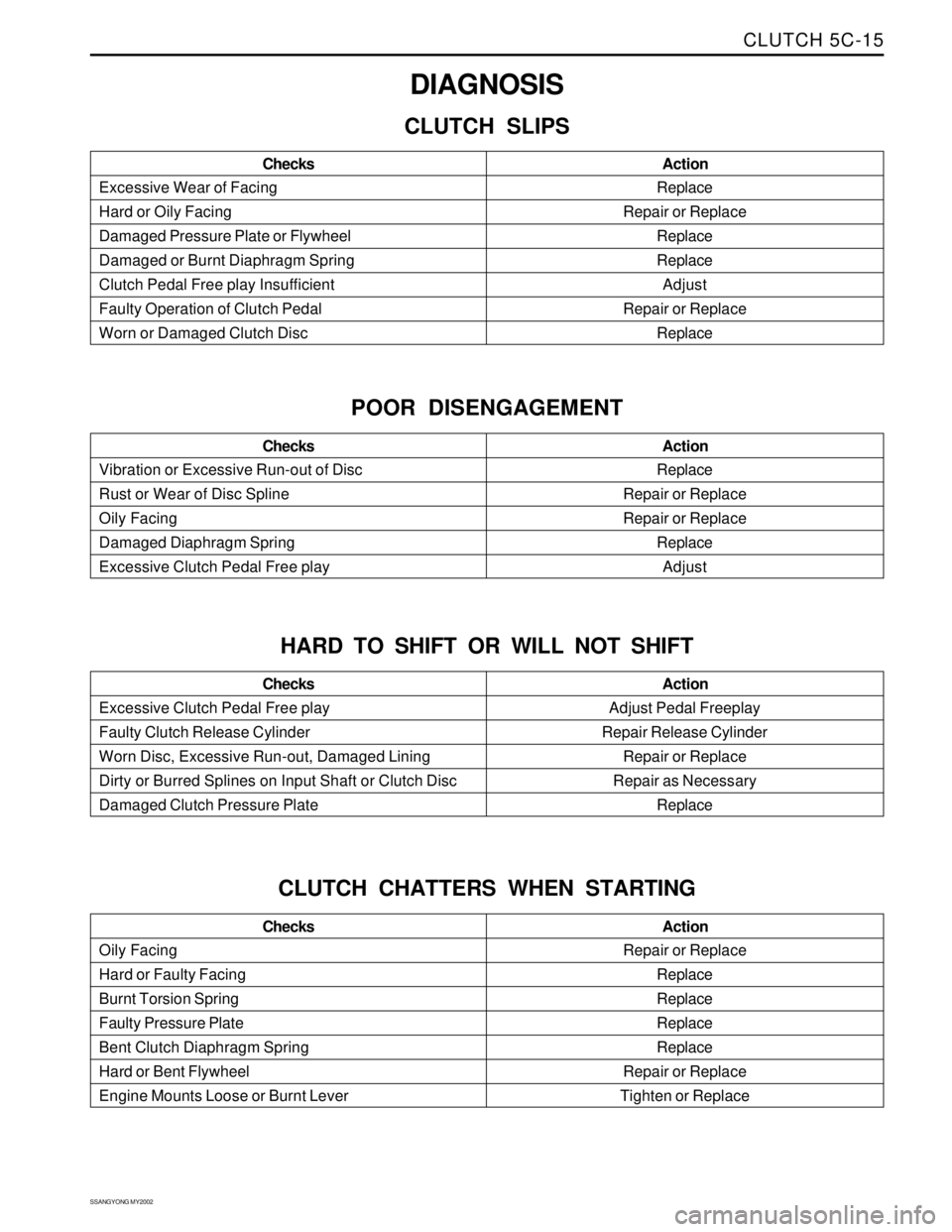
Replace
Repair or Replace
Replace
Replace
Adjust
Repair or Replace
Replace Excessive Wear of Facing
Hard or Oily Facing
Damaged Pressure Plate or Flywheel
Damaged or Burnt Diaphragm Spring
Clutch Pedal Free play Insufficient
Faulty Operation of Clutch Pedal
Worn or Damaged Clutch DiscAction Checks
DIAGNOSIS
CLUTCH SLIPS
Replace
Repair or Replace
Repair or Replace
Replace
Adjust Vibration or Excessive Run-out of Disc
Rust or Wear of Disc Spline
Oily Facing
Damaged Diaphragm Spring
Excessive Clutch Pedal Free playAction Checks
POOR DISENGAGEMENT
Adjust Pedal Freeplay
Repair Release Cylinder
Repair or Replace
Repair as Necessary
Replace Excessive Clutch Pedal Free play
Faulty Clutch Release Cylinder
Worn Disc, Excessive Run-out, Damaged Lining
Dirty or Burred Splines on Input Shaft or Clutch Disc
Damaged Clutch Pressure PlateAction Checks
HARD TO SHIFT OR WILL NOT SHIFT
Repair or Replace
Replace
Replace
Replace
Replace
Repair or Replace
Tighten or Replace Oily Facing
Hard or Faulty Facing
Burnt Torsion Spring
Faulty Pressure Plate
Bent Clutch Diaphragm Spring
Hard or Bent Flywheel
Engine Mounts Loose or Burnt LeverAction Checks
CLUTCH CHATTERS WHEN STARTING
Page 1371 of 2053
CLUTCH 5C-17
SSANGYONG MY2002
SPECIAL TOOLS AND EQUIPMENT
SPECIAL TOOLS TABLE
602 589 00 40 00
Engine Lock
KAA5C180
661 589 00 15 00
Centering Pin
KAA5C190
Page 1375 of 2053
TRANSFER CASE 5D1-5
SSANGYONG MY2002
The motor reaches its destination.
The motor is on for 5 seconds without reaching its
destination. The shift has failed and the TCCU will
respond as default mode.
A fault occurs with either the motor or position
encoder. Refer to the diagnosis requirement.
When the motor is energized, the Ignition, 4H/4L
switch, propeller shaft speeds, and transmission
neutral inputs are ignored.
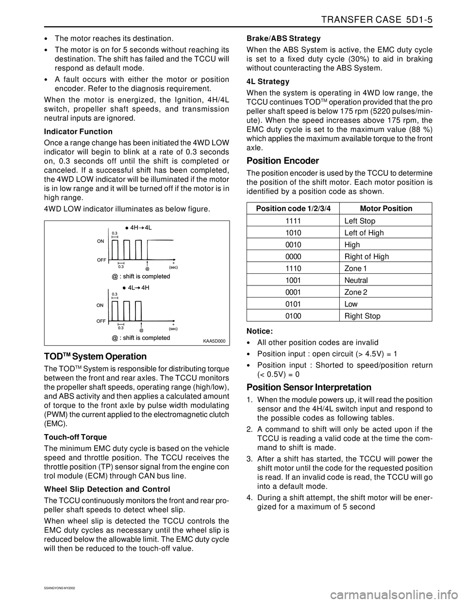
Indicator Function
Once a range change has been initiated the 4WD LOW
indicator will begin to blink at a rate of 0.3 seconds
on, 0.3 seconds off until the shift is completed or
canceled. If a successful shift has been completed,
the 4WD LOW indicator will be illuminated if the motor
is in low range and it will be turned off if the motor is in
high range.
4WD LOW indicator illuminates as below figure.
KAA5D000
TODTM System Operation
The TODTM System is responsible for distributing torque
between the front and rear axles. The TCCU monitors
the propeller shaft speeds, operating range (high/low),
and ABS activity and then applies a calculated amount
of torque to the front axle by pulse width modulating
(PWM) the current applied to the electromagnetic clutch
(EMC).
Touch-off Torque
The minimum EMC duty cycle is based on the vehicle
speed and throttle position. The TCCU receives the
throttle position (TP) sensor signal from the engine con
trol module (ECM) through CAN bus line.
Wheel Slip Detection and Control
The TCCU continuously monitors the front and rear pro-
peller shaft speeds to detect wheel slip.
When wheel slip is detected the TCCU controls the
EMC duty cycles as necessary until the wheel slip is
reduced below the allowable limit. The EMC duty cycle
will then be reduced to the touch-off value.Brake/ABS Strategy
When the ABS System is active, the EMC duty cycle
is set to a fixed duty cycle (30%) to aid in braking
without counteracting the ABS System.
4L Strategy
When the system is operating in 4WD low range, the
TCCU continues TOD
TM operation provided that the pro
peller shaft speed is below 175 rpm (5220 pulses/min-
ute). When the speed increases above 175 rpm, the
EMC duty cycle is set to the maximum value (88 %)
which applies the maximum available torque to the front
axle.
Position Encoder
The position encoder is used by the TCCU to determine
the position of the shift motor. Each motor position is
identified by a position code as shown.
Motor Position
Left Stop
Left of High
High
Right of High
Zone 1
Neutral
Zone 2
Low
Right Stop Position code 1/2/3/4
1111
1010
0010
0000
1110
1001
0001
0101
0100
Notice:
All other position codes are invalid
Position input : open circuit (> 4.5V) = 1
Position input : Shorted to speed/position return
(< 0.5V) = 0
Position Sensor Interpretation
1. When the module powers up, it will read the position
sensor and the 4H/4L switch input and respond to
the possible codes as following tables.
2. A command to shift will only be acted upon if the
TCCU is reading a valid code at the time the com-
mand to shift is made.
3. After a shift has started, the TCCU will power the
shift motor until the code for the requested position
is read. If an invalid code is read, the TCCU will go
into a default mode.
4. During a shift attempt, the shift motor will be ener-
gized for a maximum of 5 second
Page 1389 of 2053
TRANSFER CASE 5D1-67
SSANGYONG MY2002
KAA5D260
KAA5D270
TRANSFER CASE CONTROL UNIT
(TCCU)
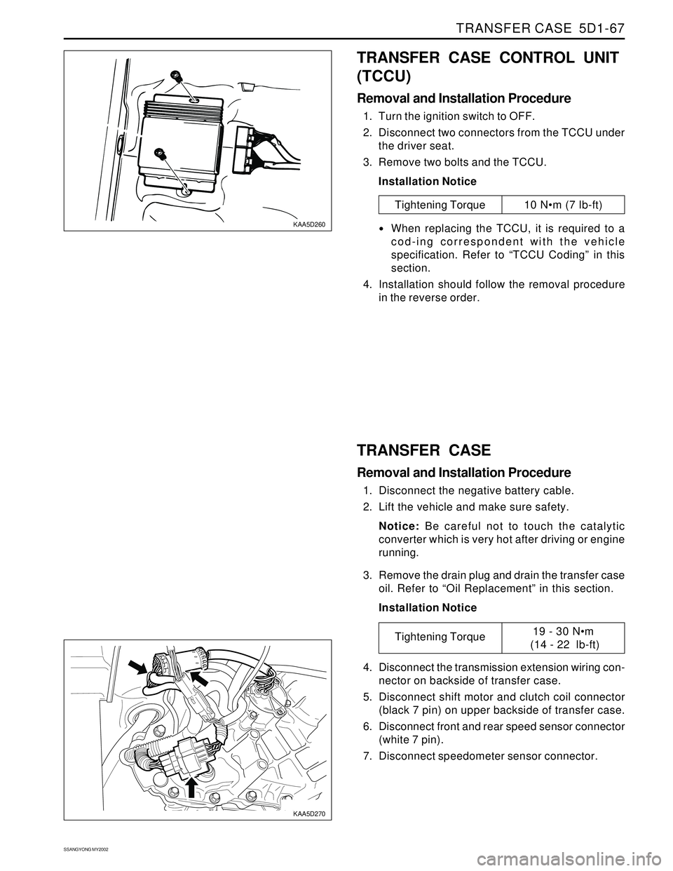
Removal and Installation Procedure
1. Turn the ignition switch to OFF.
2. Disconnect two connectors from the TCCU under
the driver seat.
3. Remove two bolts and the TCCU.
Installation Notice
Tightening Torque 10 Nm (7 lb-ft)
When replacing the TCCU, it is required to a
cod-ing correspondent with the vehicle
specification. Refer to “TCCU Coding” in this
section.
4. Installation should follow the removal procedure
in the reverse order.
TRANSFER CASE
Removal and Installation Procedure
1. Disconnect the negative battery cable.
2. Lift the vehicle and make sure safety.
Notice: Be careful not to touch the catalytic
converter which is very hot after driving or engine
running.
3. Remove the drain plug and drain the transfer case
oil. Refer to “Oil Replacement” in this section.
Installation Notice
4. Disconnect the transmission extension wiring con-
nector on backside of transfer case.
5. Disconnect shift motor and clutch coil connector
(black 7 pin) on upper backside of transfer case.
6. Disconnect front and rear speed sensor connector
(white 7 pin).
7. Disconnect speedometer sensor connector.
Tightening Torque19 - 30 Nm
(14 - 22 lb-ft)
Page 1393 of 2053
TRANSFER CASE 5D1-71
SSANGYONG MY2002
KAA5D360
KAA5D330
KAA5D380
UNIT REPAIR
TRANSFER CASE OVERHAUL
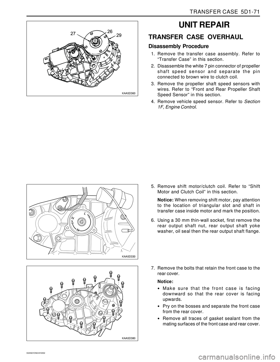
Disassembly Procedure
1. Remove the transfer case assembly. Refer to
“Transfer Case” in this section.
2. Disassemble the white 7 pin connector of propeller
shaft speed sensor and separate the pin
connected to brown wire to clutch coil.
3. Remove the propeller shaft speed sensors with
wires. Refer to “Front and Rear Propeller Shaft
Speed Sensor” in this section.
4. Remove vehicle speed sensor. Refer to Section
1F, Engine Control.
7. Remove the bolts that retain the front case to the
rear cover.
Notice:
Make sure that the front case is facing
downward so that the rear cover is facing
upwards.
Pry on the bosses and separate the front case
from the rear cover.
Remove all traces of gasket sealant from the
mating surfaces of the front case and rear cover. 5. Remove shift motor/clutch coil. Refer to “Shift
Motor and Clutch Coil” in this section.
Notice: When removing shift motor, pay attention
to the location of triangular slot and shaft in
transfer case inside motor and mark the position.
6. Using a 30 mm thin-wall socket, first remove the
rear output shaft nut, rear output shaft yoke
washer, oil seal then the rear output shaft flange.