Page 1643 of 2053
SUPPLEMENTAL RESTRAINTS SYSTEM 8B-61
SSANGYONG MY2002
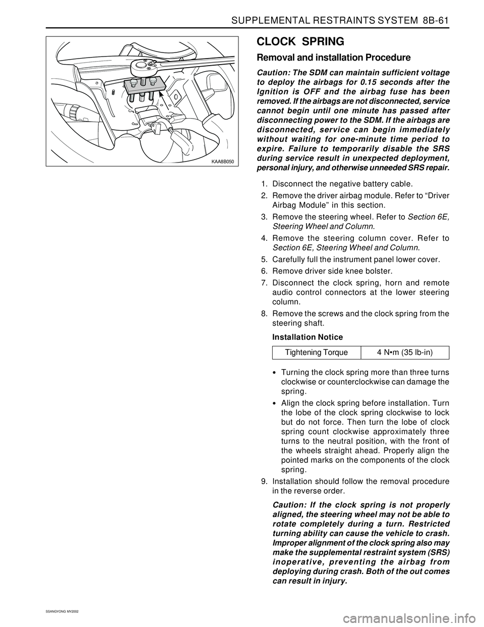
KAA8B050
CLOCK SPRING
Removal and installation Procedure
Caution: The SDM can maintain sufficient voltage
to deploy the airbags for 0.15 seconds after the
Ignition is OFF and the airbag fuse has been
removed. If the airbags are not disconnected, service
cannot begin until one minute has passed after
disconnecting power to the SDM. If the airbags are
disconnected, service can begin immediately
without waiting for one-minute time period to
expire. Failure to temporarily disable the SRS
during service result in unexpected deployment,
personal injury, and otherwise unneeded SRS repair.
1. Disconnect the negative battery cable.
2. Remove the driver airbag module. Refer to “Driver
Airbag Module” in this section.
3. Remove the steering wheel. Refer to Section 6E,
Steering Wheel and Column.
4. Remove the steering column cover. Refer to
Section 6E, Steering Wheel and Column.
5. Carefully full the instrument panel lower cover.
6. Remove driver side knee bolster.
7. Disconnect the clock spring, horn and remote
audio control connectors at the lower steering
column.
8. Remove the screws and the clock spring from the
steering shaft.
Installation Notice
Turning the clock spring more than three turns
clockwise or counterclockwise can damage the
spring.
Align the clock spring before installation. Turn
the lobe of the clock spring clockwise to lock
but do not force. Then turn the lobe of clock
spring count clockwise approximately three
turns to the neutral position, with the front of
the wheels straight ahead. Properly align the
pointed marks on the components of the clock
spring.
9. Installation should follow the removal procedure
in the reverse order.
Caution: If the clock spring is not properly
aligned, the steering wheel may not be able to
rotate completely during a turn. Restricted
turning ability can cause the vehicle to crash.
Improper alignment of the clock spring also may
make the supplemental restraint system (SRS)
inoperative, preventing the airbag from
deploying during crash. Both of the out comes
can result in injury.
Tightening Torque 4 Nm (35 lb-in)
Page 1644 of 2053
SSANGYONG MY2002
8B-62 SUPPLEMENTAL RESTRAINTS SYSTEM
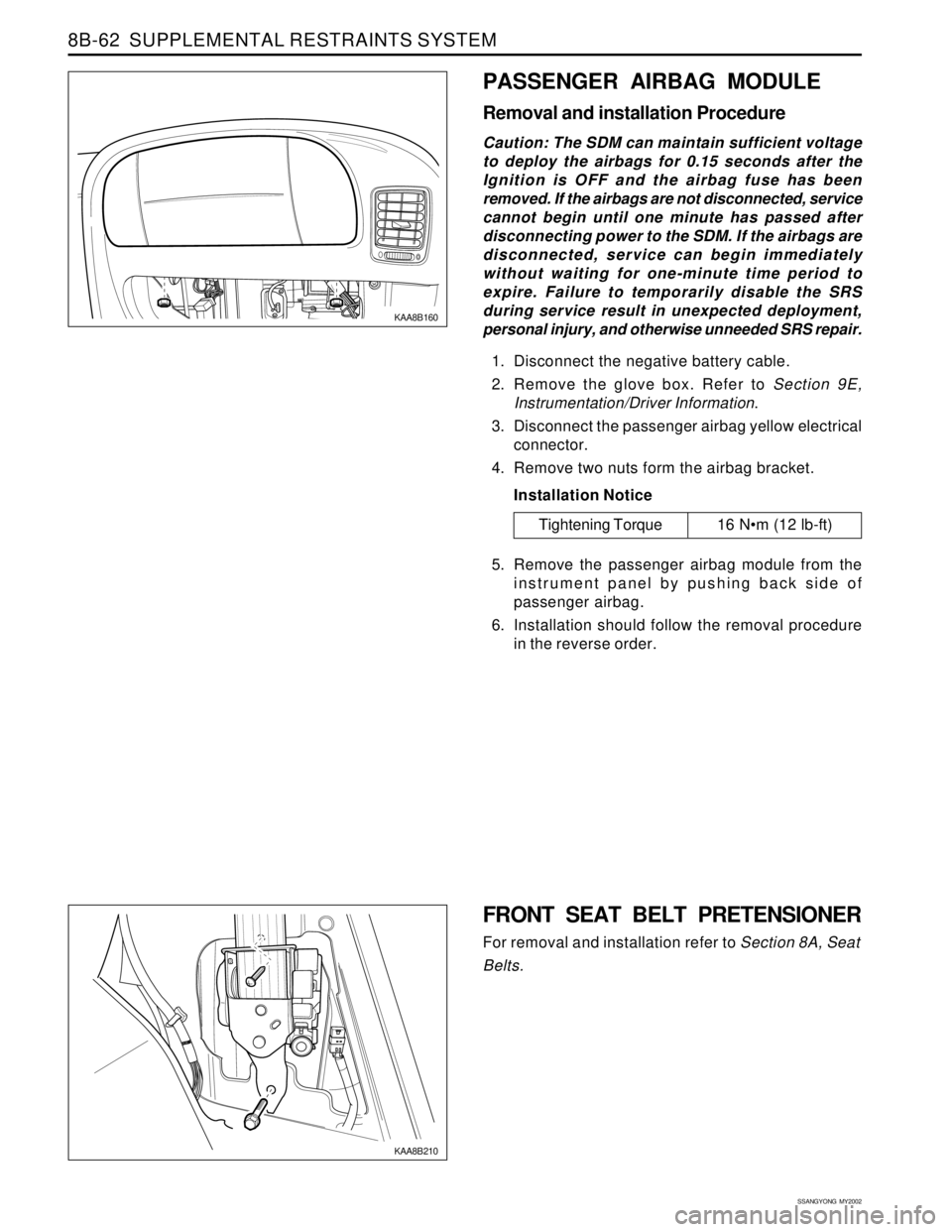
KAA8B160
PASSENGER AIRBAG MODULE
Removal and installation Procedure
Caution: The SDM can maintain sufficient voltage
to deploy the airbags for 0.15 seconds after the
Ignition is OFF and the airbag fuse has been
removed. If the airbags are not disconnected, service
cannot begin until one minute has passed after
disconnecting power to the SDM. If the airbags are
disconnected, service can begin immediately
without waiting for one-minute time period to
expire. Failure to temporarily disable the SRS
during service result in unexpected deployment,
personal injury, and otherwise unneeded SRS repair.
1. Disconnect the negative battery cable.
2. Remove the glove box. Refer to Section 9E,
Instrumentation/Driver Information.
3. Disconnect the passenger airbag yellow electrical
connector.
4. Remove two nuts form the airbag bracket.
Installation Notice
5. Remove the passenger airbag module from the
instrument panel by pushing back side of
passenger airbag.
6. Installation should follow the removal procedure
in the reverse order.
Tightening Torque 16 Nm (12 lb-ft)
FRONT SEAT BELT PRETENSIONER
For removal and installation refer to Section 8A, Seat
Belts.
KAA8B210
Page 1645 of 2053
SUPPLEMENTAL RESTRAINTS SYSTEM 8B-63
SSANGYONG MY2002
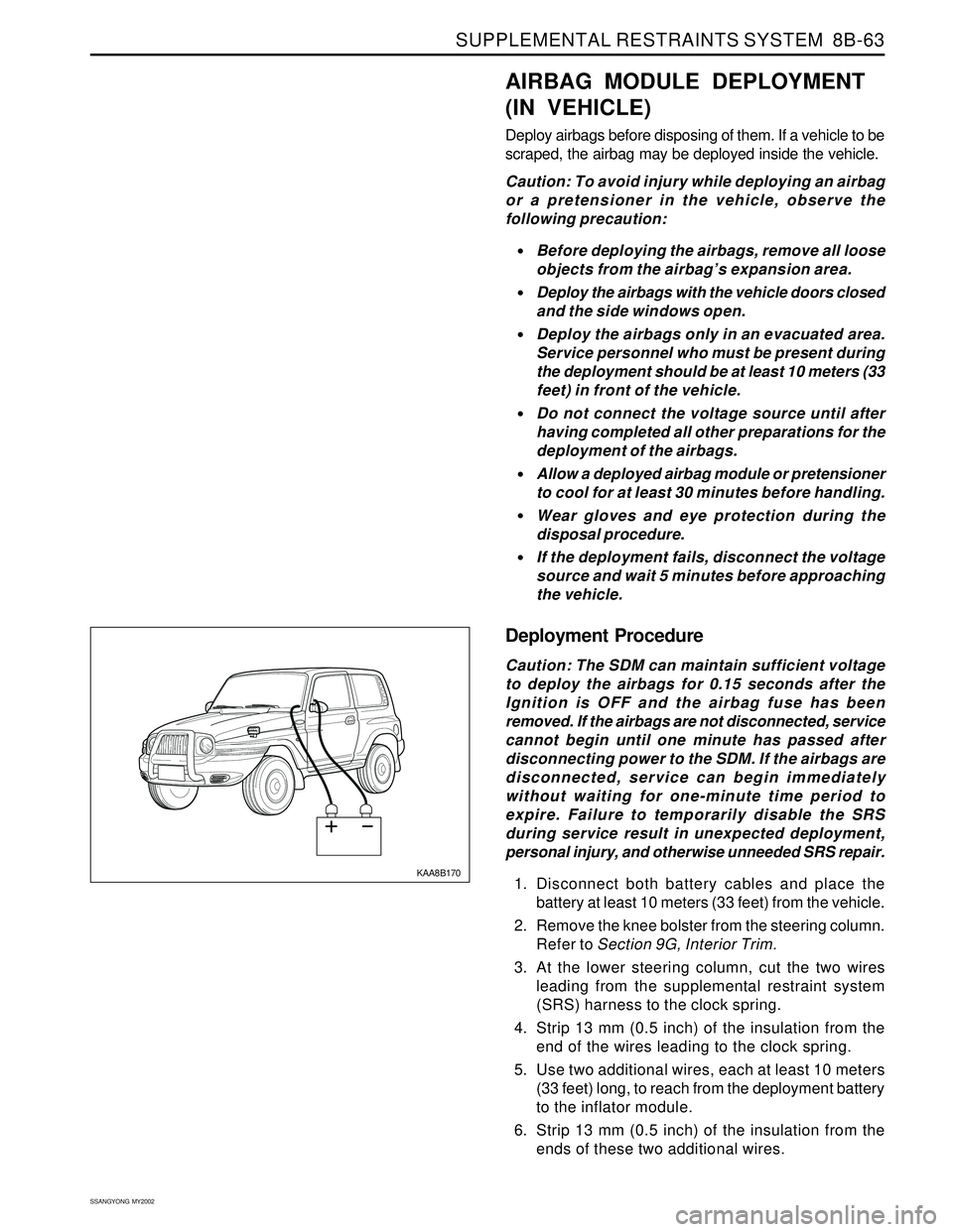
KAA8B170
AIRBAG MODULE DEPLOYMENT
(IN VEHICLE)
Deploy airbags before disposing of them. If a vehicle to be
scraped, the airbag may be deployed inside the vehicle.
Caution: To avoid injury while deploying an airbag
or a pretensioner in the vehicle, observe the
following precaution:
Before deploying the airbags, remove all loose
objects from the airbag’s expansion area.
Deploy the airbags with the vehicle doors closed
and the side windows open.
Deploy the airbags only in an evacuated area.
Service personnel who must be present during
the deployment should be at least 10 meters (33
feet) in front of the vehicle.
Do not connect the voltage source until after
having completed all other preparations for the
deployment of the airbags.
Allow a deployed airbag module or pretensioner
to cool for at least 30 minutes before handling.
Wear gloves and eye protection during the
disposal procedure.
If the deployment fails, disconnect the voltage
source and wait 5 minutes before approaching
the vehicle.
Deployment Procedure
Caution: The SDM can maintain sufficient voltage
to deploy the airbags for 0.15 seconds after the
Ignition is OFF and the airbag fuse has been
removed. If the airbags are not disconnected, service
cannot begin until one minute has passed after
disconnecting power to the SDM. If the airbags are
disconnected, service can begin immediately
without waiting for one-minute time period to
expire. Failure to temporarily disable the SRS
during service result in unexpected deployment,
personal injury, and otherwise unneeded SRS repair.
1. Disconnect both battery cables and place the
battery at least 10 meters (33 feet) from the vehicle.
2. Remove the knee bolster from the steering column.
Refer to Section 9G, Interior Trim.
3. At the lower steering column, cut the two wires
leading from the supplemental restraint system
(SRS) harness to the clock spring.
4. Strip 13 mm (0.5 inch) of the insulation from the
end of the wires leading to the clock spring.
5. Use two additional wires, each at least 10 meters
(33 feet) long, to reach from the deployment battery
to the inflator module.
6. Strip 13 mm (0.5 inch) of the insulation from the
ends of these two additional wires.
Page 1652 of 2053
SECTION 9A
BODY WIRING SYSTEM
CAUTION: Disconnect the negative battery cable before removing or installing any electrical unit or when a
tool or equipment could easily come in contact with exposed electrical terminals. Disconnecting this cable
will help prevent personal injury and damage to the vehicle. The ignition must also be in LOCK unless
otherwise noted.
TABLE OF CONTENTS
General Description.............................................9A-2
Wire Color Chart..................................................9A-2
Engine Room Fuse & Relay Box......................... 9A-3
Usage of Fuse in Engine Room Fuse Box.............9A-5
Passenger Room Fuse Box..................................9A-6
Usage of Fuse in Engine Room Fuse Box.............9A-7
Schematic and Routing Diagrams.......................9A-8
Engine Room Fuse & Relay Circuit.......................9A-8
Wiring Harness & Connector &
Ground Location................................................. 9A-11
W/H Engine Room.............................................9A-11W/H Main..........................................................9A-12
W/H Main (Floor)............................................... 9A-14
W/H Roof..........................................................9A-15
W/H Seat Heater................................................9A-16
W/H Door..........................................................9A-17
W/H Tail Gate....................................................9A-18
W/H Air-Conditioner...........................................9A-19
W/H Engine Control (Gasoline)...........................9A-20
W/H Pre-Heating (Diesel)...................................9A-21
W/H Transmission..............................................9A-22
Page 1654 of 2053
BODY WIRING SYSTEM 9A-3
SSANGYONG MY2002
ENGINE ROOM FUSE & RELAY BOX
Position Of Relay And Fuse (Front View)
KAA9A010
Page 1655 of 2053
SSANGYONG MY2002
9A-4 BODY WIRING SYSTEM
Position Of Relay And Fuse (Rear View)
KAA9A020
Page 1656 of 2053
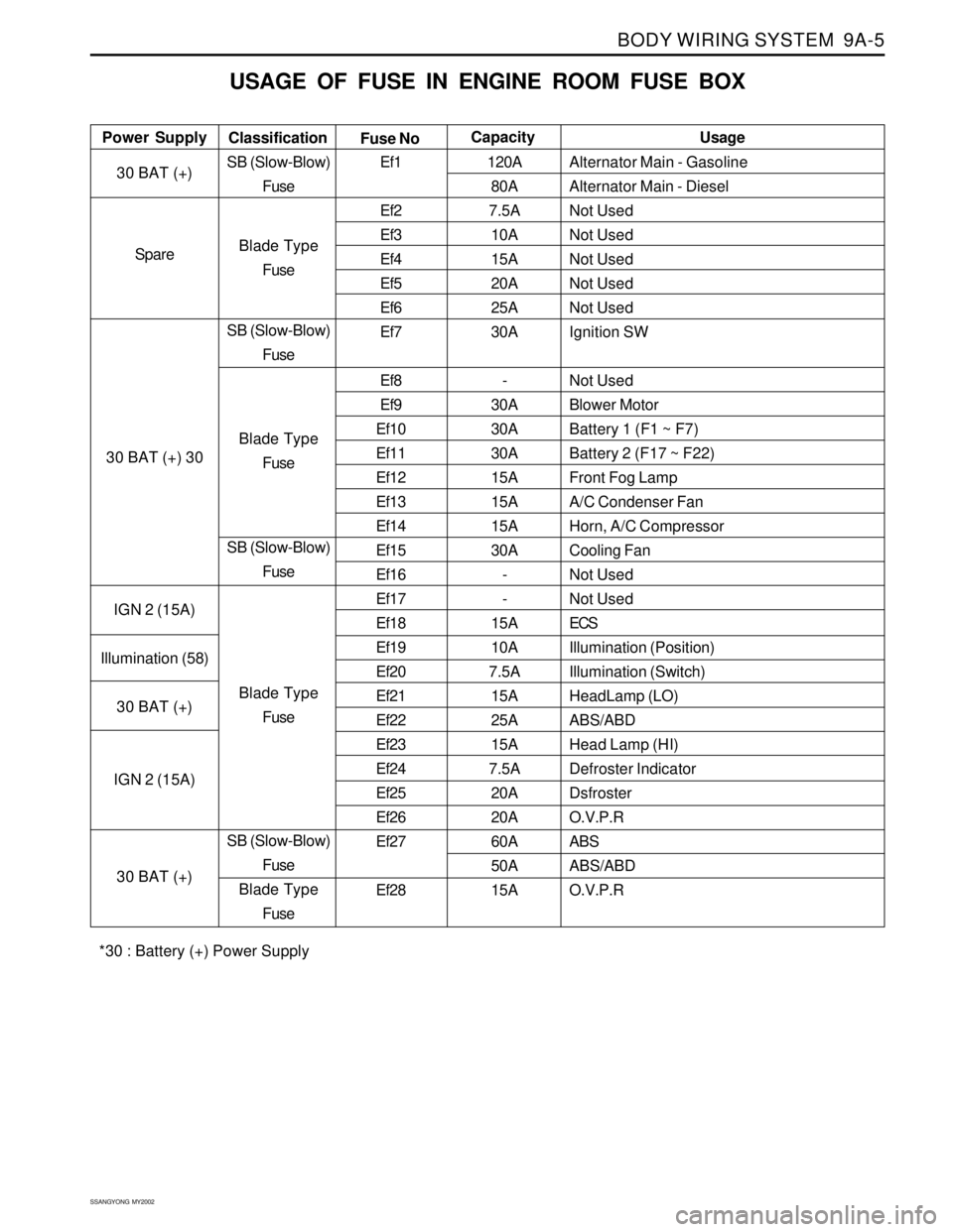
BODY WIRING SYSTEM 9A-5
SSANGYONG MY2002
USAGE OF FUSE IN ENGINE ROOM FUSE BOX
Alternator Main - Gasoline
Alternator Main - Diesel
Not Used
Not Used
Not Used
Not Used
Not Used
Ignition SW
Not Used
Blower Motor
Battery 1 (F1 ~ F7)
Battery 2 (F17 ~ F22)
Front Fog Lamp
A/C Condenser Fan
Horn, A/C Compressor
Cooling Fan
Not Used
Not Used
ECS
Illumination (Position)
Illumination (Switch)
HeadLamp (LO)
ABS/ABD
Head Lamp (HI)
Defroster Indicator
Dsfroster
O.V.P.R
ABS
ABS/ABD
O.V.P.R Power SupplyUsage
Classification
Fuse NoCapacity
30 BAT (+)
Spare
30 BAT (+) 30
IGN 2 (15A)
Illumination (58)
30 BAT (+)
IGN 2 (15A)
30 BAT (+)SB (Slow-Blow)
Fuse
Blade Type
Fuse
SB (Slow-Blow)
Fuse
Blade Type
Fuse
SB (Slow-Blow)
Fuse
Blade Type
Fuse
SB (Slow-Blow)
Fuse
Blade Type
FuseEf1
Ef2
Ef3
Ef4
Ef5
Ef6
Ef7
Ef8
Ef9
Ef10
Ef11
Ef12
Ef13
Ef14
Ef15
Ef16
Ef17
Ef18
Ef19
Ef20
Ef21
Ef22
Ef23
Ef24
Ef25
Ef26
Ef27
Ef28120A
80A
7.5A
10A
15A
20A
25A
30A
-
30A
30A
30A
15A
15A
15A
30A
-
-
15A
10A
7.5A
15A
25A
15A
7.5A
20A
20A
60A
50A
15A
*30 : Battery (+) Power Supply
Page 1657 of 2053
SSANGYONG MY2002
9A-6 BODY WIRING SYSTEM
PASSENGER ROOM FUSE BOX
Position of Fuse
KAA9A030