1997 SSANGYONG KORANDO fuse
[x] Cancel search: fusePage 1723 of 2053
SSANGYONG MY2002
9E-6 INSTRUMENTATION, DRIVER INFORMATION
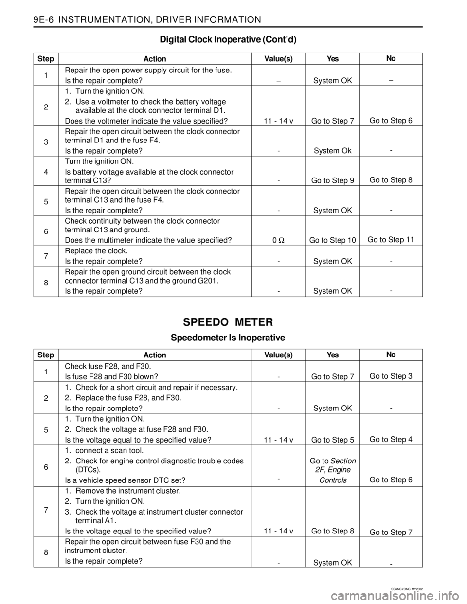
Digital Clock Inoperative (Cont’d)
Step
1
2
3
4
5
6
7
8Action
Repair the open power supply circuit for the fuse.
Is the repair complete?
1. Turn the ignition ON.
2. Use a voltmeter to check the battery voltage
available at the clock connector terminal D1.
Does the voltmeter indicate the value specified?
Repair the open circuit between the clock connector
terminal D1 and the fuse F4.
Is the repair complete?
Turn the ignition ON.
Is battery voltage available at the clock connector
terminal C13?
Repair the open circuit between the clock connector
terminal C13 and the fuse F4.
Is the repair complete?
Check continuity between the clock connector
terminal C13 and ground.
Does the multimeter indicate the value specified?
Replace the clock.
Is the repair complete?
Repair the open ground circuit between the clock
connector terminal C13 and the ground G201.
Is the repair complete?Yes
System OK
Go to Step 7
System Ok
Go to Step 9
System OK
Go to Step 10
System OK
System OKNo
−
Go to Step 6
-
Go to Step 8
-
Go to Step 11
-
- Value(s)
−
11 - 14 v
-
-
-
0 Ω
-
-
SPEEDO METER
Speedometer Is Inoperative
Step
1
2
5
6
7
8Action
Check fuse F28, and F30.
Is fuse F28 and F30 blown?
1. Check for a short circuit and repair if necessary.
2. Replace the fuse F28, and F30.
Is the repair complete?
1. Turn the ignition ON.
2. Check the voltage at fuse F28 and F30.
Is the voltage equal to the specified value?
1. connect a scan tool.
2. Check for engine control diagnostic trouble codes
(DTCs).
Is a vehicle speed sensor DTC set?
1. Remove the instrument cluster.
2. Turn the ignition ON.
3. Check the voltage at instrument cluster connector
terminal A1.
Is the voltage equal to the specified value?
Repair the open circuit between fuse F30 and the
instrument cluster.
Is the repair complete?Yes
Go to Step 7
System OK
Go to Step 5
Go to Section
2F, Engine
Controls
Go to Step 8
System OKNo
Go to Step 3
-
Go to Step 4
Go to Step 6
Go to Step 7
- Value(s)
-
-
11 - 14 v
-
11 - 14 v
-
Page 1726 of 2053
INSTRUMENTATION, DRIVER INFORMATION 9E-9
SSANGYONG MY2002
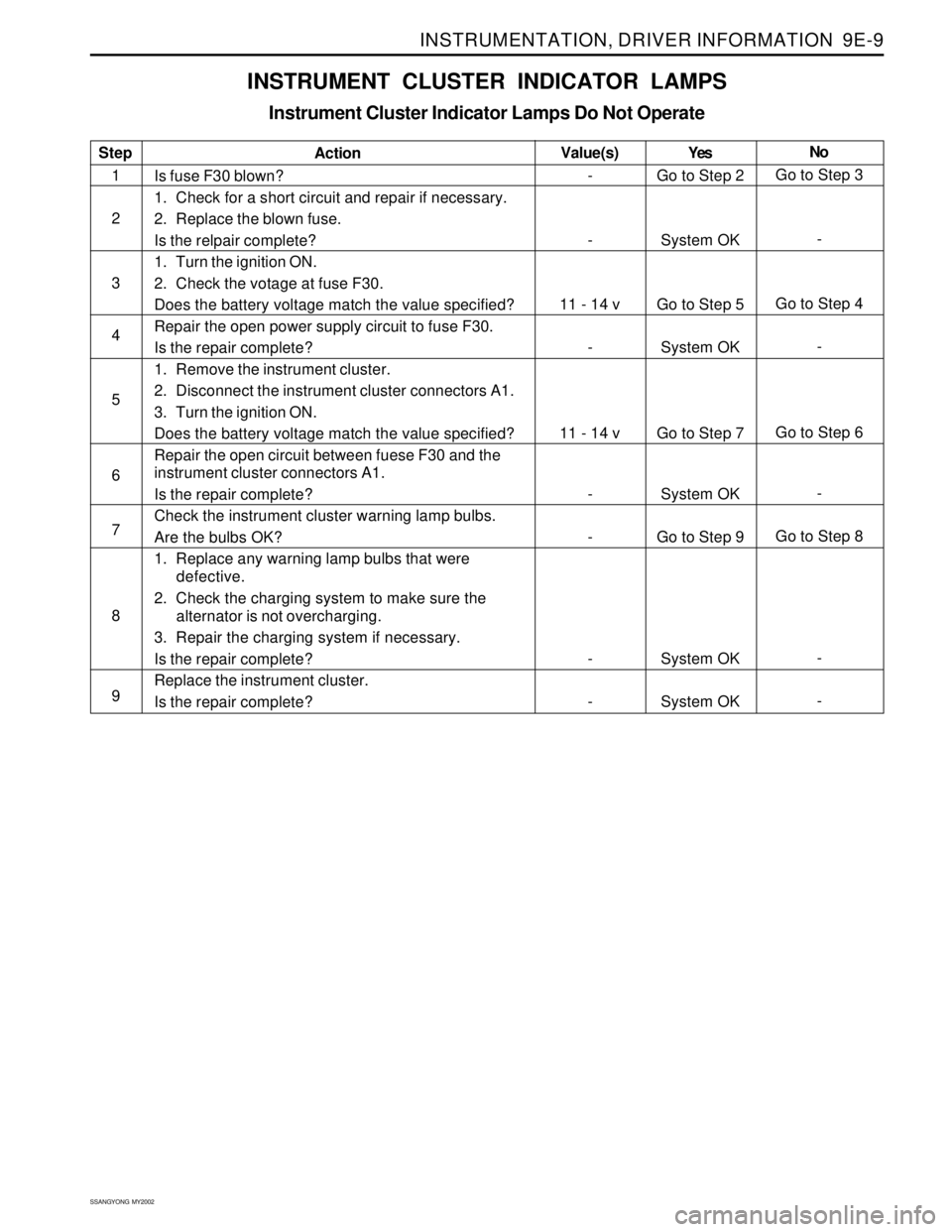
INSTRUMENT CLUSTER INDICATOR LAMPS
Instrument Cluster Indicator Lamps Do Not Operate
Step
1
2
3
4
5
6
7
8
9Action
Is fuse F30 blown?
1. Check for a short circuit and repair if necessary.
2. Replace the blown fuse.
Is the relpair complete?
1. Turn the ignition ON.
2. Check the votage at fuse F30.
Does the battery voltage match the value specified?
Repair the open power supply circuit to fuse F30.
Is the repair complete?
1. Remove the instrument cluster.
2. Disconnect the instrument cluster connectors A1.
3. Turn the ignition ON.
Does the battery voltage match the value specified?
Repair the open circuit between fuese F30 and the
instrument cluster connectors A1.
Is the repair complete?
Check the instrument cluster warning lamp bulbs.
Are the bulbs OK?
1. Replace any warning lamp bulbs that were
defective.
2. Check the charging system to make sure the
alternator is not overcharging.
3. Repair the charging system if necessary.
Is the repair complete?
Replace the instrument cluster.
Is the repair complete?Yes
Go to Step 2
System OK
Go to Step 5
System OK
Go to Step 7
System OK
Go to Step 9
System OK
System OKNo
Go to Step 3
-
Go to Step 4
-
Go to Step 6
-
Go to Step 8
-
- Value(s)
-
-
11 - 14 v
-
11 - 14 v
-
-
-
-
Page 1781 of 2053

SQUEAKS AND RATTLES 9K-3
SSANGYONG MY2002
Check for a lack of lubrication of the door hinge pins.ChecksActionOperate the doors and listen for squeaks.
Lubricate the door hinge pins with light oil and coat
with lithium grease.
Squeak Coming From Console When Shifting Manual Transaxle
(Condition Occurs In Cold Weather with a Cold Engine)
Check the manual transaxle control lever lower boot.ChecksActionMove the control lever between gears and listen for
squeaks.
Remove the floor console and replace the lower shift
boot or apply talcum powder to the lower shift boot.
Squeak When Operating Doors
Check for vibration of the fuse box cover against the
instrument panel side trim.ChecksActionTap on thecoverwith a fingerandlisten fora buzz.
Apply 6.35 mm (0.250 inch) by 25.4 mm (1.00 inch)
felt pads to the side trim where the cover makes
contact.
Squeak Coming From Instrument Cluster Trim Plate
Check for rubbing of the cluster trim plate on the
instrument panel.ChecksActionTest drive the vehicle in order to verify this condi-
tion.
Remove the instrument cluster trim plate and install
felt tape to the edges.
Buzz From the Left Side of Instrument Panel
Check the door lock solenoid.
Check for rattling electrical connectors inside the door
trim panel.ChecksActionRemove the door trim panel and check if the sole-
noid is loose.
Tighten the solenoid bolts.
Tap on the trim panel and listen for a rattle.
Remove the trim panel and wrap foam padding
around the connectors as required.
Rattle Coming From Door
Page 1863 of 2053
1-2 1-2 1-2 1-2
1-2
HOW TO USE ELECTRICAL WIRING DIAGRAM HOW TO USE ELECTRICAL WIRING DIAGRAMHOW TO USE ELECTRICAL WIRING DIAGRAM HOW TO USE ELECTRICAL WIRING DIAGRAM
HOW TO USE ELECTRICAL WIRING DIAGRAM1. 1.1. 1.
1.
HO HOHO HO
HO
W W W W
W
T TT T
T
O READ ELECTRICAL O READ ELECTRICAL O READ ELECTRICAL O READ ELECTRICAL
O READ ELECTRICAL
WIRING DIA WIRING DIAWIRING DIA WIRING DIA
WIRING DIA
GRAM GRAMGRAM GRAM
GRAM
1) 1)1) 1)
1)
CONTENTS OF ELECTRICAL WIRING DIAGRAM (CIRCUIT) CONTENTS OF ELECTRICAL WIRING DIAGRAM (CIRCUIT)CONTENTS OF ELECTRICAL WIRING DIAGRAM (CIRCUIT) CONTENTS OF ELECTRICAL WIRING DIAGRAM (CIRCUIT)
CONTENTS OF ELECTRICAL WIRING DIAGRAM (CIRCUIT)
POSITION POSITIONPOSITION POSITION
POSITION
EXPLANATION EXPLANATIONEXPLANATION EXPLANATION
EXPLANATION
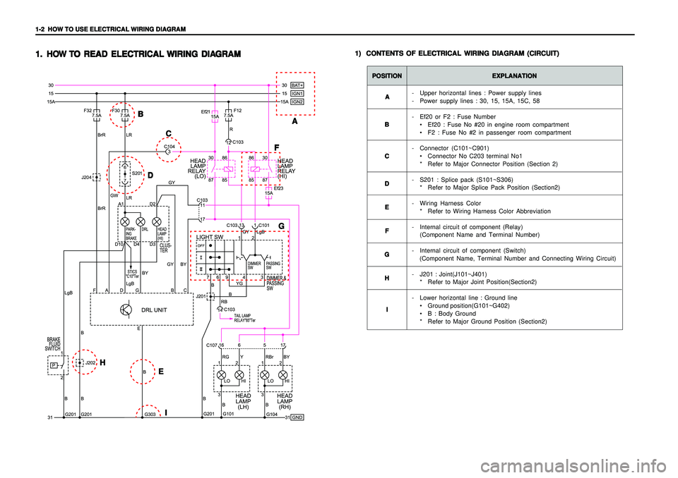
- Upper horizontal lines : Power supply lines
- Power supply lines : 30, 15, 15A, 15C, 58
- Ef20 or F2 : Fuse Number
• Ef20 : Fuse No #20 in engine room compartment
F2 : Fuse No #2 in passenger room compartment
- Connector (C101~C901)
Connector No C203 terminal No1
* Refer to Major Connector Position (Section 2)
- S201 : Splice pack (S101~S306)
* Refer to Major Splice Pack Position (Section2)
- Wiring Harness Color
* Refer to Wiring Harness Color Abbreviation
- Internal circuit of component (Relay)
(Component Name and Terminal Number)
- Internal circuit of component (Switch)
(Component Name, Terminal Number and Connecting Wiring Circuit)
- J201 : Joint(J101~J401)
* Refer to Major Joint Position(Section2)
- Lower horizontal line : Ground line
Ground position(G101~G402)
B : Body Ground
* Refer to Major Ground Position (Section2) A AA A
A
B BB B
B
C CC C
C
D DD D
D
E EE E
E
F FF F
F
G GG G
G
H HH H
H
I II I
I
A AA A
A B BB B
B
C CC C
C
D DD D
DF FF F
F
G GG G
G
E EE E
E
I II I
I H HH H
H
Page 1864 of 2053
HOW TO USE ELECTRICAL WIRING DIAGRAM HOW TO USE ELECTRICAL WIRING DIAGRAM HOW TO USE ELECTRICAL WIRING DIAGRAM HOW TO USE ELECTRICAL WIRING DIAGRAM
HOW TO USE ELECTRICAL WIRING DIAGRAM
1-3 1-31-3 1-3
1-3
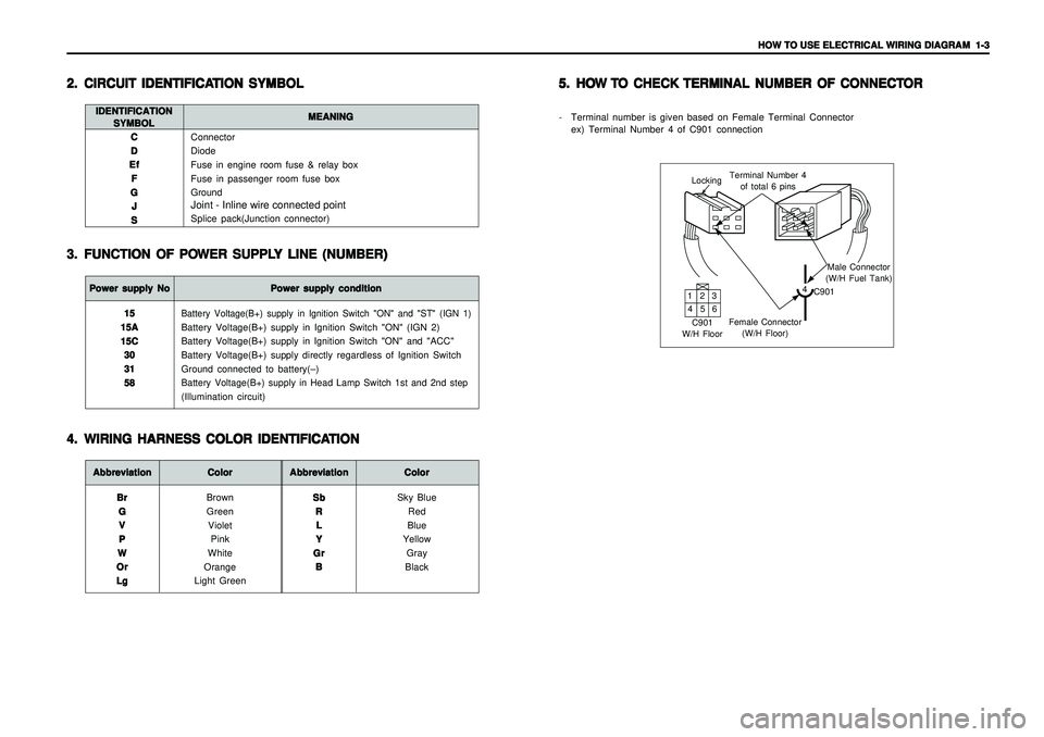
Connector
Diode
Fuse in engine room fuse & relay box
Fuse in passenger room fuse box
GroundJoint - Inline wire connected pointSplice pack(Junction connector) C CC C
C
D DD D
D
Ef EfEf Ef
Ef
F FF F
F
G GG G
G
J JJ J
J
S SS S
S
2. 2.2. 2.
2.
CIRCUIT IDENTIFICA CIRCUIT IDENTIFICACIRCUIT IDENTIFICA CIRCUIT IDENTIFICA
CIRCUIT IDENTIFICA
TION SYMBOL TION SYMBOLTION SYMBOL TION SYMBOL
TION SYMBOL
3. 3.3. 3.
3.
FUNCTION OF PO FUNCTION OF POFUNCTION OF PO FUNCTION OF PO
FUNCTION OF PO
WER SUPPL WER SUPPLWER SUPPL WER SUPPL
WER SUPPL
Y LINE (NUMBER) Y LINE (NUMBER)Y LINE (NUMBER) Y LINE (NUMBER)
Y LINE (NUMBER)
IDENTIFICATION IDENTIFICATIONIDENTIFICATION IDENTIFICATION
IDENTIFICATION
SYMBOL SYMBOLSYMBOL SYMBOL
SYMBOLMEANING MEANINGMEANING MEANING
MEANINGPower supply No Power supply NoPower supply No Power supply No
Power supply No
Power supply condition Power supply conditionPower supply condition Power supply condition
Power supply condition
Battery Voltage(B+) supply in Ignition Switch "ON" and "ST" (IGN 1)Battery Voltage(B+) supply in Ignition Switch "ON" (IGN 2)
Battery Voltage(B+) supply in Ignition Switch "ON" and "ACC"
Battery Voltage(B+) supply directly regardless of Ignition Switch
Ground connected to battery(–)Battery Voltage(B+) supply in Head Lamp Switch 1st and 2nd step(Illumination circuit) 15 1515 15
15
15A 15A15A 15A
15A
15C 15C15C 15C
15C
30 3030 30
30
31 3131 31
31
58 5858 58
58
Abbreviation AbbreviationAbbreviation Abbreviation
Abbreviation
Color ColorColor Color
Color
Brown
Green
Violet
Pink
White
Orange
Light Green Br BrBr Br
Br
G GG G
G
V VV V
V
P PP P
P
W WW W
W
Or OrOr Or
Or
Lg LgLg Lg
Lg
Abbreviation AbbreviationAbbreviation Abbreviation
Abbreviation
Color ColorColor Color
Color
Sky Blue
Red
Blue
Yellow
Gray
Black Sb SbSb Sb
Sb
R RR R
R
L LL L
L
Y YY Y
Y
Gr GrGr Gr
Gr
B BB B
B
4. 4.4. 4.
4.
WIRING HARNESS COLOR IDENTIFICA WIRING HARNESS COLOR IDENTIFICAWIRING HARNESS COLOR IDENTIFICA WIRING HARNESS COLOR IDENTIFICA
WIRING HARNESS COLOR IDENTIFICA
TION TIONTION TION
TION5. 5.5. 5.
5.
HO HOHO HO
HO
W W W W
W
T TT T
T
O CHECK O CHECK O CHECK O CHECK
O CHECK
TERMINAL NUMBER OF CONNECT TERMINAL NUMBER OF CONNECTTERMINAL NUMBER OF CONNECT TERMINAL NUMBER OF CONNECT
TERMINAL NUMBER OF CONNECT
OR OROR OR
OR
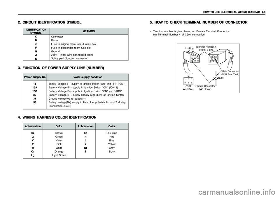
- Terminal number is given based on Female Terminal Connector
ex) Terminal Number 4 of C901 connection
LockingTerminal Number 4
of total 6 pins
Male Connector
(W/H Fuel Tank)
4
C901
Female Connector
(W/H Floor) C901
W/H Floor132
465
Page 1865 of 2053
HOW TO USE ELECTRICAL WIRING DIAGRAM HOW TO USE ELECTRICAL WIRING DIAGRAM HOW TO USE ELECTRICAL WIRING DIAGRAM HOW TO USE ELECTRICAL WIRING DIAGRAM
HOW TO USE ELECTRICAL WIRING DIAGRAM
1-3 1-31-3 1-3
1-3
Connector
Diode
Fuse in engine room fuse & relay box
Fuse in passenger room fuse box
GroundJoint - Inline wire connected pointSplice pack(Junction connector) C CC C
C
D DD D
D
Ef EfEf Ef
Ef
F FF F
F
G GG G
G
J JJ J
J
S SS S
S
2. 2.2. 2.
2.
CIRCUIT IDENTIFICA CIRCUIT IDENTIFICACIRCUIT IDENTIFICA CIRCUIT IDENTIFICA
CIRCUIT IDENTIFICA
TION SYMBOL TION SYMBOLTION SYMBOL TION SYMBOL
TION SYMBOL
3. 3.3. 3.
3.
FUNCTION OF PO FUNCTION OF POFUNCTION OF PO FUNCTION OF PO
FUNCTION OF PO
WER SUPPL WER SUPPLWER SUPPL WER SUPPL
WER SUPPL
Y LINE (NUMBER) Y LINE (NUMBER)Y LINE (NUMBER) Y LINE (NUMBER)
Y LINE (NUMBER)
IDENTIFICATION IDENTIFICATIONIDENTIFICATION IDENTIFICATION
IDENTIFICATION
SYMBOL SYMBOLSYMBOL SYMBOL
SYMBOLMEANING MEANINGMEANING MEANING
MEANINGPower supply No Power supply NoPower supply No Power supply No
Power supply No
Power supply condition Power supply conditionPower supply condition Power supply condition
Power supply condition
Battery Voltage(B+) supply in Ignition Switch "ON" and "ST" (IGN 1)Battery Voltage(B+) supply in Ignition Switch "ON" (IGN 2)
Battery Voltage(B+) supply in Ignition Switch "ON" and "ACC"
Battery Voltage(B+) supply directly regardless of Ignition Switch
Ground connected to battery(–)Battery Voltage(B+) supply in Head Lamp Switch 1st and 2nd step(Illumination circuit) 15 1515 15
15
15A 15A15A 15A
15A
15C 15C15C 15C
15C
30 3030 30
30
31 3131 31
31
58 5858 58
58
Abbreviation AbbreviationAbbreviation Abbreviation
Abbreviation
Color ColorColor Color
Color
Brown
Green
Violet
Pink
White
Orange
Light Green Br BrBr Br
Br
G GG G
G
V VV V
V
P PP P
P
W WW W
W
Or OrOr Or
Or
Lg LgLg Lg
Lg
Abbreviation AbbreviationAbbreviation Abbreviation
Abbreviation
Color ColorColor Color
Color
Sky Blue
Red
Blue
Yellow
Gray
Black Sb SbSb Sb
Sb
R RR R
R
L LL L
L
Y YY Y
Y
Gr GrGr Gr
Gr
B BB B
B
4. 4.4. 4.
4.
WIRING HARNESS COLOR IDENTIFICA WIRING HARNESS COLOR IDENTIFICAWIRING HARNESS COLOR IDENTIFICA WIRING HARNESS COLOR IDENTIFICA
WIRING HARNESS COLOR IDENTIFICA
TION TIONTION TION
TION5. 5.5. 5.
5.
HO HOHO HO
HO
W W W W
W
T TT T
T
O CHECK O CHECK O CHECK O CHECK
O CHECK
TERMINAL NUMBER OF CONNECT TERMINAL NUMBER OF CONNECTTERMINAL NUMBER OF CONNECT TERMINAL NUMBER OF CONNECT
TERMINAL NUMBER OF CONNECT
OR OROR OR
OR
- Terminal number is given based on Female Terminal Connector
ex) Terminal Number 4 of C901 connection
LockingTerminal Number 4
of total 6 pins
Male Connector
(W/H Fuel Tank)
4
C901
Female Connector
(W/H Floor) C901
W/H Floor132
465
Page 1868 of 2053
2-4 2-4 2-4 2-4
2-4
ELECTRICAL WIRING DIAGRAMS ELECTRICAL WIRING DIAGRAMSELECTRICAL WIRING DIAGRAMS ELECTRICAL WIRING DIAGRAMS
ELECTRICAL WIRING DIAGRAMS
Engine Room Fuse Box - W/H Main
Engine Room Fuse Box - W/H Main
Engine Room Fuse Box - W/H Main
Engine Room FuseBox - W/H Main
Engine Room Fuse Box - W/H Engine Room
Engine Room Fuse Box - W/H Engine Room
Engine Room Fuse Box - W/H Engine Room
Engine Room Fuse Box - W/H Engine Room
W/H Engine Room - W/H Pre - Heating
W/H Engine Room - W/H Alternator
W/H Engine Room - W/H Alternator
W/H Engine Room - W/H Wheel G. sensor
W/H Engine Room - W/H Main
W/H Engine Room - W/H Main
W/H Engine Control - W/H ECM Main
W/H Engine Control - W/H ECM Main
W/H Main - W/H Fuel Cut Solenoid
W/H Main - W/H Roof
W/H Main - W/H Air Bag
W/H Main - W/H Air Bag
W/H Main - W/H SDM
W/H Main - W/H Air Conditioner
W/H Main - W/H ECM Main
W/H Main - W/H Transmission
W/H Main - W/H Transmission
W/H Main - W/H Transmission
W/H Main - W/H Fuel Pump
W/H Main - W/H Fuel Pump
W/H Main - W/H Fuel Pump
W/H Main - W/H Seat Heater
W/H Main - W/H Main
W/H Main - W/H FRT LH Door
W/H FRT LH Door - W/H Speaker
W/H Main - W/H FRT RH Door
W/H FRT RH Door - W/H Speaker
G201W/H Main Upper Front Left Leg Room
G202W/H Main Upper Front Left Leg Room
G203W/H Main Left Upper Center Facia
G204W/H Main Left Lower Center Facia
G205W/H Main Center "A" Pillar Front Right
G301W/H Main Below Front Left seat
G302W/H Main Below Center Console
G303W/H Main Below Front Right seat
G401W/H Main Inside Lower Trim Rear Left Quater
Engine Room Fuse Box
Engine Room Fuse Box
Engine Room Fuse Box
Engine Room Fuse Box
Engine Room Fuse Box
Engine Room Fuse Box
Engine Room Fuse Box
Engine Room Fuse Box
Bhind Battery
Below Air Cleaner
Below Air Cleaner
Upper Front Right Control Arm
Next to Hydraulic Unit
Next to Hydraulic Unit
Behind Hydraulic Unit
Behind Hydraulic Unit
Next to Engine Room Fuse Box
Inside Left Cluster
Above FRT LH Seat Under Cover
Above FRT LH Seat Under Cover
Lower Rear Center Facia
Upper Evaporator
Lower "A" Piller(Upper ECM)
Upper Transfer Case
Upper Transfer Case
Upper Transfer Case
Upper Transfer Case
Upper Transfer Case
Upper Transfer Case
Below FRT LH Seat
Below Center Console
Upper Fuse Box
(Passenger Room)
Inside FRT LH Door Trim
Behind Front Right Panel
Inside FRT RH Door Trim
2. 2.2. 2.
2.
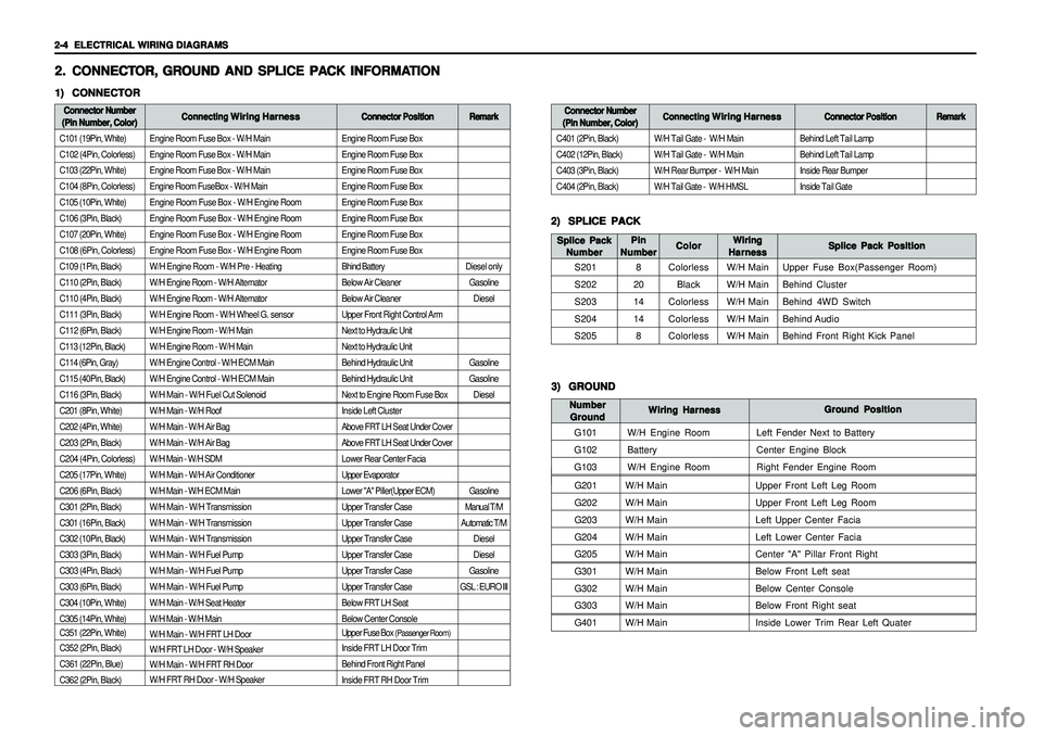
CONNECT CONNECTCONNECT CONNECT
CONNECT
OR, OR,OR, OR,
OR,
GR GR GR GR
GR
OUND AND SPLICE PA OUND AND SPLICE PAOUND AND SPLICE PA OUND AND SPLICE PA
OUND AND SPLICE PA
CK INFORMA CK INFORMACK INFORMA CK INFORMA
CK INFORMA
TION TIONTION TION
TION1) 1)1) 1)
1)
CONNECTOR CONNECTORCONNECTOR CONNECTOR
CONNECTORConnector Number Connector NumberConnector Number Connector Number
Connector Number
(Pin Number, Color) (Pin Number, Color)(Pin Number, Color) (Pin Number, Color)
(Pin Number, Color)Connecting Connecting Connecting Connecting
Connecting
Wiring Harness Wiring HarnessWiring Harness Wiring Harness
Wiring Harness
Connector Position Connector PositionConnector Position Connector Position
Connector Position
C101 (19Pin, White)
C102 (4Pin, Colorless)
C103 (22Pin, White)
C104 (8Pin, Colorless)
C105 (10Pin, White)
C106 (3Pin, Black)
C107 (20Pin, White)
C108 (6Pin, Colorless)
C109 (1Pin, Black)
C110 (2Pin, Black)
C110 (4Pin, Black)
C111 (3Pin, Black)
C112 (6Pin, Black)
C113 (12Pin, Black)
C114 (6Pin, Gray)
C115 (40Pin, Black)
C116 (3Pin, Black)
C201 (8Pin, White)
C202 (4Pin, White)
C203 (2Pin, Black)
C204 (4Pin, Colorless)
C205 (17Pin, White)
C206 (6Pin, Black)
C301 (2Pin, Black)
C301 (16Pin, Black)
C302 (10Pin, Black)
C303 (3Pin, Black)
C303 (4Pin, Black)
C303 (6Pin, Black)
C304 (10Pin, White)
C305 (14Pin, White)
C351 (22Pin, White)
C352 (2Pin, Black)
C361 (22Pin, Blue)
C362 (2Pin, Black)
2) 2)2) 2)
2)
SPLICE PACK SPLICE PACKSPLICE PACK SPLICE PACK
SPLICE PACK
S201
S202
S203
S204
S205Splice Pack Position Splice Pack PositionSplice Pack Position Splice Pack Position
Splice Pack Position Wiring WiringWiring Wiring
Wiring
Harness HarnessHarness Harness
Harness Color ColorColor Color
Color Splice Pack Splice PackSplice Pack Splice Pack
Splice Pack
Number NumberNumber Number
Number
Colorless
Black
Colorless
Colorless
ColorlessW/H Main
W/H Main
W/H Main
W/H Main
W/H MainUpper Fuse Box(Passenger Room)
Behind Cluster
Behind 4WD Switch
Behind Audio
Behind Front Right Kick Panel
Remark RemarkRemark Remark
Remark
Diesel only
Gasoline
Diesel
Gasoline
Gasoline
Diesel
Gasoline
Manual T/M
Automatic T/M
Diesel
Diesel
Gasoline
GSL : EURO IIIBehind Left Tail Lamp
Behind Left Tail Lamp
Inside Rear Bumper
Inside Tail Gate
Connector Number Connector NumberConnector Number Connector Number
Connector Number
(Pin Number, Color) (Pin Number, Color)(Pin Number, Color) (Pin Number, Color)
(Pin Number, Color)Connecting Connecting Connecting Connecting
Connecting
Wiring Harness Wiring HarnessWiring Harness Wiring Harness
Wiring Harness
Connector Position Connector PositionConnector Position Connector Position
Connector Position
C401 (2Pin, Black)
C402 (12Pin, Black)
C403 (3Pin, Black)
C404 (2Pin, Black)W/H Tail Gate - W/H Main
W/H Tail Gate - W/H Main
W/H Rear Bumper - W/H Main
W/H Tail Gate - W/H HMSL
Remark RemarkRemark Remark
Remark
3) 3)3) 3)
3)
GROUND GROUNDGROUND GROUND
GROUND
G101
G102
G103Ground Position Ground PositionGround Position Ground Position
Ground Position
Wiring Harness Wiring HarnessWiring Harness Wiring Harness
Wiring Harness Number NumberNumber Number
Number
Ground GroundGround Ground
Ground
W/H Engine Room
Battery
W/H Engine RoomLeft Fender Next to Battery
Center Engine Block
Right Fender Engine Room
Pin PinPin Pin
Pin
Number NumberNumber Number
Number
8
20
14
14
8
Page 1870 of 2053
2-6 2-6 2-6 2-6
2-6
ELECTRICAL WIRING DIAGRAMS ELECTRICAL WIRING DIAGRAMSELECTRICAL WIRING DIAGRAMS ELECTRICAL WIRING DIAGRAMS
ELECTRICAL WIRING DIAGRAMS3. 3.3. 3.
3.
WIRING HARNESS & CONNECT WIRING HARNESS & CONNECTWIRING HARNESS & CONNECT WIRING HARNESS & CONNECT
WIRING HARNESS & CONNECT
OR & GR OR & GROR & GR OR & GR
OR & GR
OUND LOCA OUND LOCAOUND LOCA OUND LOCA
OUND LOCA
TION TIONTION TION
TION1) 1)1) 1)
1)
W/H ENGINE ROOM W/H ENGINE ROOMW/H ENGINE ROOM W/H ENGINE ROOM
W/H ENGINE ROOM
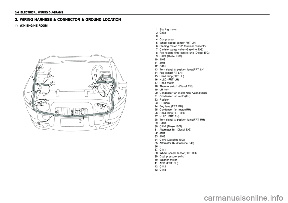
1. Starting motor
2. G102
3. -
4. Compressor
5. Wheel speed sensor(FRT LH)
6. Starting motor "ST" terminal connector
7. Canister purge valve (Gasoline E/G)
8. Pre-heating time control unit (Diesel E/G)
9. C109 (Diesel E/G)
10. J102
11. J101
12. G101
13. Turn signal & position lamp(FRT LH)
14. Fog lamp(FRT LH)
15. Head lamp(FRT LH)
16. HLLD (FRT LH)
17. Hood switch
18. Thermo switch (Diesel E/G)
19. LH horn
20. Condenser fan motor-Non A/conditioner
21. Condenser fan motor(LH)
22. Resistor
23. RH horn
24. Fog lamp(FRT RH)
25. Condenser fan motor(RH)
26. Head lamp(FRT RH)
27. HLLD (FRT RH)
28. Turn signal & position lamp(FRT RH)
29. G103
30. C110 (Diesel E/G)
31. Alternator B+ (Diesel E/G)
32. J104
33. J103
34. C110 (Gasoline E/G)
35. Alternator B+ (Gasoline E/G)
36. -
37. C111
38. Wheel speed sensor(FRT RH)
39. Dual pressure switch
40. Washer motor
41. ADD (FRT RH)
42. C112
43. C113
FUSE &RELAY BOX
42
43
41
40
393435
37303138
2928
25
26
24
23
2221201918
17
1516
13
12111089
7
6
5
4321
14
27
3233