Page 922 of 2053

SSAMGYONG MY2002
4A-2 HYDRAULIC BRAKES
DESCRIPTION AND OPERATION
GENERAL DESCRIPTION
Brake fluid should meet the DOT 4 specification. Use
only clear fluid from a sealed container.
Fluid that is exposed to the air will absorb moisture.
Water in the brake fluid will cause the fluid to boil and
the rubber components to deteriorate.
Thoroughly clean the master cylinder reservoir cap be-
fore removing it. Do not let any dirt or foreign material
fall into the fluid reservoir.
There is a brake fluid level switch under the master
cylinder reservoir.When the fluid level is low, the BRAKE lamp in the
instrument cluster will turn on.
The correct brake fluid level is marked on the both
side of the brake fluid reservoir. If the fluid level is
below the MIN indicator mark, check the hydraulic brake
system for leaks. Fix any leaks. Then refill the reservoir
to the MAX indicator mark.
The hydraulic brake system is parallel split on Antilock
Brake Systems. This means the left front and left rear
brakes are on one hydraulic circuit and the right front
and right rear are on the other.
Page 925 of 2053

HYDRAULIC BRAKES 4A-5
SSANGYONG MY2002
Value(s)
-
-
-
-
-
-
-
-
-
-
-
-
-
-
BRAKE WARNING LAMP DIAGNOSIS
Step
1
2
3
4
5
6
7
8
9
10
11
12
13
14Action
Start the engine and leave it running.
Does the BRAKE warning lamp stay on?
With the engine running, release the parking brake.
Is the BRAKE warning lamp off?
Check the brake fluid level.
Is the fluid level OK?
1. Fill the brake fluid reservoir with clean DOT-3
hydraulic fluid.
2. Check the cap on the fluid reservoir.
3. Start the engine and leave it running.
Is the BRAKE warning lamp on?
Disconnect the wiring harness connector from the
brake fluid level switch.
Is the BRAKE warning lamp on?
Replace the brake fluid lever switch.
Is the repair complete?
1. Connect the brake fluid level switch.
2. Disconnect the parking brake lever switch.
3. Start the engine and leave it running.
Is the BRAKE warning lamp on?
Replace the parking brake lever switch.
Is the repair complete?
1. Connect the parking brake lever switch.
2. Disconnect the STICS (Super Time and Alarm
Integrated System).
3. Start the engine and leave it running.
Is the BRAKE warning lamp on?
Replace the STICS.
Is the repair complete?
Repair the short circuit in the instrument wiring
harness between terminal D10 of the instrument
cluster and ground.
Is the repair complete?
1. Disconnect the electrical connector from the fluid
level switch.
2. Connect a jumper wire between ground and
terminal 1 of the fluid level switch harness
connector.
Does the BRAKE warning lamp turn on?
1. Disconnect the electrical connector from the fluid
level switch.
2. Connect a jump wire between terminals 1 and 2
of the fluid level switch harness connector.
Does the BRAKE warning lamp turn on?
1. Replace the brake fluid level switch.
2 The switch can be removed and replaced without
draining the brake fluid from the reservoir.
Is the repair complete?Yes
Go To Step 2
System OK
Go To Step 5
Go To Step 5
Go To Step 7
System OK
Go To Step 9
System OK
Go To Step 11
System OK
System OK
Go To Step 13
Go To Step 14
System OKNO
Go To Step 12
Go To Step 3
Go To Step 4
System OK
Go To Step 6
-
Go To Step 8
-
Go To Step 10
-
-
Go To Step 15
Go To Step 15
-
Page 926 of 2053

SSAMGYONG MY2002
4A-6 HYDRAULIC BRAKES
Action
1. Turn the ignition ON.
2. Apply the parking brake.
Does the BRAKE warning lamp turn on?
Check fuse F30.
Is fuse F30 blown?
Check for a short circuit and repair it, if necessary.
Replace fuse F30.
1. Turn the ignition ON.
2. Check the voltage at F30.
Is the voltage equal to the specified value?
Repair the power supply to fuse F30.
Is the repair complete?
1. Disconnect terminal A1 of the instrument cluster.
2. Turn the ignition ON.
3. Use a voltmeter to check the voltage at terminal A1.
Is the voltage equal to the specified value?
Repair the open circuit between terminal A1 of the
instrument cluster and fuse F30.
Is the repair complete?
1. Reconnect terminal A1 of the instrument cluster.
Turn the ignition ON.
2. Use a voltmeter to backprobe terminal D10 of the
instrument cluster.
Is the voltage equal to the specified value?
1. Remove the BRAKE warning lamp from its socket.
2. Test the Brake warning lamp.
Is the BRAKEwarning lamp OK?
Replace the instrument cluster.
Is the repair complete?
Replace the BRAKE warning lamp.
Is the repair complete?
1. Disconnect terminal C10 of the STICS.
2. Connect a jumper wire between terminal C10 and
ground.
3. Turn the ignition ON.
Is the BRAKE warning lamp on?
Replace the STICS.
Is the repair complete?
1. Disconnect the STICS connector.
2. Connect a jump wire between terminal C19 and
ground.
3. Turn the ignition ON.
Is the BRAKE warning lamp on?
Replace the brake warning lamp switch.
Is the repair complete?
Repair the open circuit between the brake warning
lamp switch and terminal C19 of the STICS
BRAKE LAMP WARNING CIRCUIT (Cont’d)
Yes
Go To Step 31
Go To Step 17
System OK
Go To Step 20
System OK
Go To Step 22
System OK
Go To Step 26
Go To Step 24
System OK
System OK
Go To Step 27
System OK
Go To Step 29
System OK
System OKNO
Go To Step 16
Go To Step 18
-
Go To Step 19
-
Go To Step 21
-
Go To Step 23
Go To Step 25
-
-
Go To Step 28
-
Go To Step 30
-
-Step
15
16
17
18
19
20
21
22
23
24
25
26
27
28
29
30Value
-
-
-
11 - 14 v
-
11 - 14 v
-
11 - 14 v
-
-
-
-
-
-
-
-
Page 927 of 2053
HYDRAULIC BRAKES 4A-7
SSANGYONG MY2002
BRAKE LAMP WARNING CIRCUIT (Cont’d)
Action
1. Disconnect the brake fluid level switch.
2. Use an ohmmeter to check the resistance between
terminal 2 of the switch connector and ground.
Is the resistance equal to the specified value?
Repair the open circuit between ground and the brake
fluid level switch.
Is the repair complete?
Repair the open circuit between terminal 1 of the brake
fluid level switch and terminal D10 of the instrument
cluster.
Is the repair complete?Yes
Go To Step 32
System OK
System OKNO
Go To Step 33
-
-Step
31
32
33Value(s)
≈ 0 Ω
-
-
Page 1003 of 2053

SSANGYONG MY2002
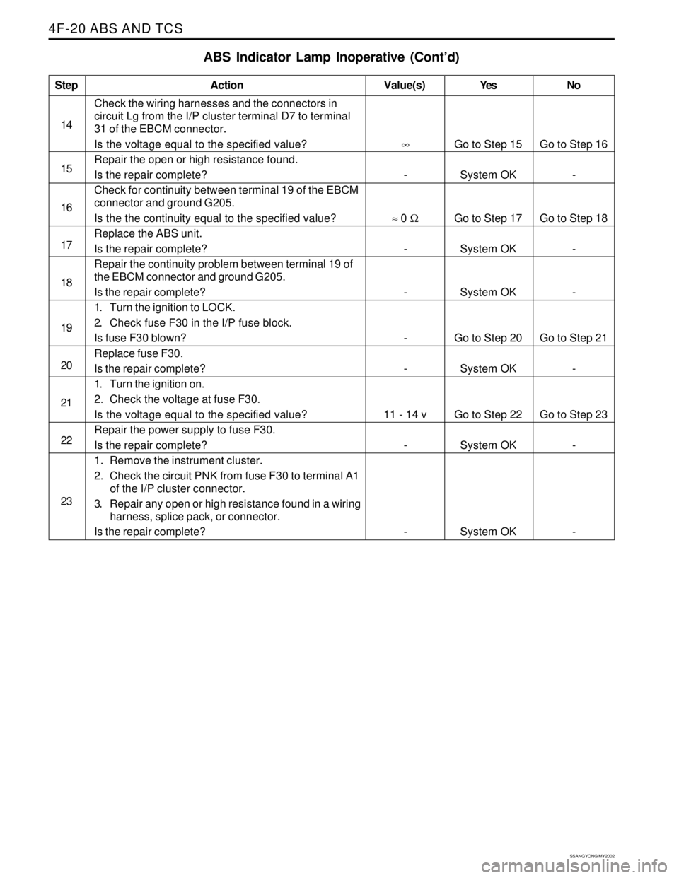
4F-20 ABS AND TCS
Go to Step 15
System OK
Go to Step 17
System OK
System OK
Go to Step 20
System OK
Go to Step 22
System OK
System OK Value(s) Step
14
15
16
17
18
19
20
21
22
23
ABS Indicator Lamp Inoperative (Cont’d)
Action Yes No
Check the wiring harnesses and the connectors in
circuit Lg from the I/P cluster terminal D7 to terminal
31 of the EBCM connector.
Is the voltage equal to the specified value?
Repair the open or high resistance found.
Is the repair complete?
Check for continuity between terminal 19 of the EBCM
connector and ground G205.
Is the the continuity equal to the specified value?
Replace the ABS unit.
Is the repair complete?
Repair the continuity problem between terminal 19 of
the EBCM connector and ground G205.
Is the repair complete?
1. Turn the ignition to LOCK.
2. Check fuse F30 in the I/P fuse block.
Is fuse F30 blown?
Replace fuse F30.
Is the repair complete?
1. Turn the ignition on.
2. Check the voltage at fuse F30.
Is the voltage equal to the specified value?
Repair the power supply to fuse F30.
Is the repair complete?
1. Remove the instrument cluster.
2. Check the circuit PNK from fuse F30 to terminal A1
of the I/P cluster connector.
3. Repair any open or high resistance found in a wiring
harness, splice pack, or connector.
Is the repair complete?
∞
-
≈ 0 Ω
-
-
-
-
11 - 14 v
-
-Go to Step 16
-
Go to Step 18
-
-
Go to Step 21
-
Go to Step 23
-
-
Page 1085 of 2053
SSANGYONG MY2002
4F-102 ABS AND TCS
ACCELERATION SENSOR
Removal and Installation Procedure
1. Disconnect the negative battery cable.
2. Disconnect the acceleration sensor connector. It
is located at the rear of audio system.
3. Remove the acceleration sensor mounting bolts.
Installation Notice
SYSTEM FUSE
Removal and Installation Procedure
The ABS/TCS system fuse, EF11, is located in the
engine fuse block. Counting from the battery toward
the surge tank, it is the first system fuse in the row.
KAA4F410
KAA4F420
Tightening Torque 7 Nm (62 lb-in)
4. Installation should follow the removal procedure in
the reverse order.
INDICATORS
The indicator lamps ABS and EBD and TCS are part of
the instrument cluster. Refer to Section 9E, instrumenta-
tion/ Driver information, for removal and replacement
details.
Page 1089 of 2053
SSANGYONG MY2002
4G-2 PARKING BRAKE
DESCRIPTION AND OPERATION
BRAKE CALIPER
This braking system uses a BRAKE warning light lo-
cated in the instrument panel cluster.
The following conditions will activate the BRAKE lamp:
•The parking brake is applied when the ignition is
ON. The lamp will turn off when the parking brake
is released.
The fluid level is below the minimum mark in the
master cylinder reservoir. The lamp will turn off when
the fluid level is above the minimum.
As a test of the lamp circuit, the BRAKE lamp will
glow dimly when the ignition is ON, even if the
parking brake is off and fluid level is above the
minimum. The lamp will turn off when the engine is
started. When the brake is firmly applied, the parking
brake should hold the vehicle with ample pedal
travel remaining.
Check for frayed cables, rust, etc. or any condition
that may inhibit present (or future) free movement of
the parking brake lever assembly.
Page 1092 of 2053

PARKING BRAKE 4G-5
SSANGYONG MY2002
KAA4G040
KAA4G050
KAA4G060
KAA4G070
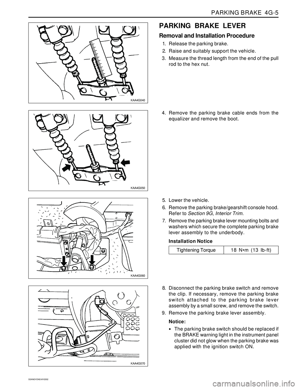
PARKING BRAKE LEVER
Removal and Installation Procedure
1. Release the parking brake.
2. Raise and suitably support the vehicle.
3. Measure the thread length from the end of the pull
rod to the hex nut.
5. Lower the vehicle.
6. Remove the parking brake/gearshift console hood.
Refer to Section 9G, Interior Trim.
7. Remove the parking brake lever mounting bolts and
washers which secure the complete parking brake
lever assembly to the underbody.
Installation Notice
8. Disconnect the parking brake switch and remove
the clip. If necessary, remove the parking brake
switch attached to the parking brake lever
assembly by a small screw, and remove the switch.
9. Remove the parking brake lever assembly.
Notice:
The parking brake switch should be replaced if
the BRAKE warning light in the instrument panel
cluster did not glow when the parking brake was
applied with the ignition switch ON.
Tightening Torque 18 Nm (13 lb-ft) 4. Remove the parking brake cable ends from the
equalizer and remove the boot.