1997 SSANGYONG KORANDO instrument cluster
[x] Cancel search: instrument clusterPage 1102 of 2053
5A-8 AUTOMATIC TRANSMISSION
SSANGYONG MY2002
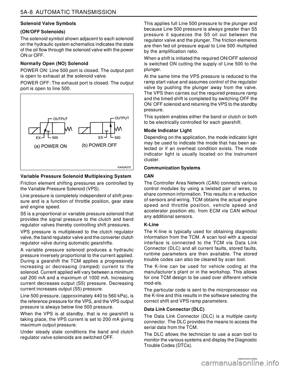
Solenoid Valve Symbols
(ON/OFF Solenoids)
The solenoid symbol shown adjacent to each solenoid
on the hydraulic system schematics indicates the state
of the oil flow through the solenoid valve with the power
ON or OFF.
Normally Open (NO) Solenoid
POWER ON: Line 500 port is closed. The output port
is open to exhaust at the solenoid valve.
POWER OFF: The exhaust port is closed. The output
port is open to line 500.
Variable Pressure Solenoid Multiplexing System
Friction element shifting pressures are controlled by
the Variable Pressure Solenoid (VPS).
Line pressure is completely independent of shift pres-
sure and is a function of throttle position, gear state
and engine speed.
S5 is a proportional or variable pressure solenoid that
provides the signal pressure to the clutch and band
regulator valves thereby controlling shift pressures.
VPS pressure is multiplexed to the clutch regulator
valve, the band regulator valve and the converter clutch
regulator valve during automatic gearshifts.
A variable pressure solenoid produces a hydraulic
pressure inversely proportional to the current applied.
During a gearshift the TCM applies a progressively
increasing or decreasing (ramped) current to the
solenoid. Current applied will vary between a minimum
oaf 200 mA and a maximum of 1000 mA. Increasing
current decreases output (S5) pressure. Decreasing
current increases output (S5) pressure.
Line 500 pressure, (approximately 440 to 560 kPa), is
the reference pressure for the VPS, and the VPS output
pressure is always below line 500 pressure.
When the VPS is at standby, that is no gearshift is
taking place, the VPS current is set to 200 mA giving
maximum output pressure.
Under steady state conditions the band and clutch
regulator valve solenoids are switched OFF.This applies full Line 500 pressure to the plunger and
because Line 500 pressure is always greater than S5
pressure it squeezes the S5 oil out between the
regulator valve and the plunger. The friction elements
are then fed oil pressure equal to Line 500 multiplied
by the amplification ratio.
When a shift is initiated the required ON/OFF solenoid
is switched ON cutting the supply of Line 500 to the
plunger.
At the same time the VPS pressure is reduced to the
ramp start value and assumes control of the regulator
valve by pushing the plunger away from the valve.
The VPS then carries out the required pressure ramp
and the timed shift is completed by switching OFF the
ON/ OFF solenoid and returning the VPS to the standby
pressure.
This system enables either the band or clutch or both
to be electrically controlled for each gearshift.
Mode Indicator Light
Depending on the application, the mode indicator light
may be used to indicate the mode that has been se-
lected or if an overheat condition exists. The mode
indicator light is usually located on the instrument
cluster.
Communication Systems
CAN
The Controller Area Network (CAN) connects various
control modules by using a twisted pair of wires, to
share common information. This results in a reduction
of sensors and wiring. TCM obtains the actual engine
speed and throttle position, vehicle speed and
accelerator position etc. from ECM via CAN without
any additional sensors.
K-Line
The K-line is typically used for obtaining diagnostic
information from the TCM. A scan tool with a special
interface is connected to the TCM via Data Link
Connector (DLC) and all current faults, stored faults,
runtime parameters are then available. The stored
trouble codes can also be cleared by scan tool.
The K-line can be used for vehicle coding at the
manufacturer’s plant or in the workshop. This allows
for one TCM design to be used over different vehicle
mod-els.
The particular code is sent to the microprocessor via
the K-line and this results in the software selecting the
correct shift and VPS ramp parameters.
Data Link Connector (DLC)
The Data Link Connector (DLC) is a multiple cavity
connector. The DLC provides the means to access the
serial data from the TCM.
The DLC allows the technician to use a scan tool to
monitor the various systems and display the Diagnostic
Trouble Codes (DTCs).
KAA5A070
Page 1578 of 2053
SSANGYONG MY2002
8A-2 SEAT BELTS
DESCRIPTION AND OPERATION
DRIVER SEAT BELT WARNING
The driver’s seat belt incorporates a seat belt warning
lamp in the instrument cluster to remind the driver if
the seat belt is not fastened when the ignition is turned
ON. The warning lamp blinks for eight seconds with
chime and goes out.
THREE-POINT FRONT SEAT BELT
WITH PRETENSIONER
The front seat belt contains an electronically controlled
pyrotechnic retractor, pretensioner, which reduces seat
belt slack when it activated in a head-on or angled
front collision. The front seat belt must be replaced
after an accident that causes its activation. At normal
condition the driver’s seat belt operates as emergency
locking retractor (ELR).
Emergency Locking Retractor (ELR)
The ELR seat belt is always unlocked, allowing the
passenger freedom of movement, except in
emergencies such as rapid deceleration, rapid
acceleration, or hard cornering maneuvers.
THREE-POINT REAR OUTBOARD
SEAT BELT
The rear outboard seating position uses the emergency
locking retractor (ELR). Refer to Three-point front seat
belt with pretensioner in this section for details.
TWO-POINT LAP REAR CENTER
SEAT BELT
The two-point lap rear center seat belt is a single contin-
uous length of webbing. The webbing is routed from
the anchor through plate and into a single retractor.
OPERATIONAL AND FUNCTIONAL
CHECKS
Caution:
Keep sharp objects and potentially damaged ob
jects away from seat belts.
Avoid bending or damaging any portion of
buckle or the latch plate
Do not breach or dye the belt webbing. Use only
mild soap and water in order to clean the belts.
When installing the seat belt anchor bolts and
screws, start the bolts and screws by hand in or-
der to prevent cross-threading.
Do not attempt any repairs on the retractor mech-
anisms or covers. Replace any defective assem-
blies with new assemblies.
Replace any belts that are cut or damaged in any
way.
1. Inspect all seat anchor bolts and screws in order to
verify that they are secure.
2. Inspect the seat belt buckle. The buckle must lock
and unlock easily.
3. After inserting the latch into the buckle, tug sharply
on the belt. The buckle must remain locked.
4. Fully extend the shoulder belt portion to make sure
that there is no twisting or tears in the belt.
5. Let the shoulder belt retract fully. The belt should
retract easily.
CHILD SEAT TETHER ANCHOR
There are three child seat tether anchors to hold the
child seat firmly. One is located rear center of ceiling
and two are located on the rear corner of floor.
Page 1588 of 2053
SUPPLEMENTAL RESTRAINTS SYSTEM 8B-3
SSANGYONG MY2002
SUPPLEMENTAL RESTRAINT
SYSTEM (SRS)
The supplemental restraint system (SRS) is safety de-
vice used in conjunction with the seat belts.
The air bag does not replace the function of the
seatbelt. The driver and the passengers must always
fasten their seat belts adjust them for a proper fit.
The SRS is designed to protect the driver and the front
seat passenger in the event of a significant frontal im-
pact to the vehicle. The airbags deploy if the force is
applied from a direction within about 30 degrees of
the vehicle’s centerline.
The SRS system consists of the following components:
Driver side airbag module.
Passenger airbag module.
Driver’s and passengers front seat belt pretension-
ers.
Sensing and diagnostic module (SDM).
Clock spring.
Wire harness and connectors.
Airbag warning lamp on the instrument cluster.
There are there are for separate four separate deploy-
ment loops in the SRS system. The term “loop” is
used because current leaves the SDM and returns to
the SDM during deployment or testing. First loop is
the circuit from SDM to the driver airbag and back to
the SDM. Second loop is the circuit from the SDM to
the passenger airbag and back to the SDM. The third
and forth loops are for right and left pretensioners.
DESCRIPTION AND OPERATION
KAA8B010
deployment, the system will enter overall or partial
shutdown status and the airbag will not inflate. The
Diagnostic System Check reveals diagnostic trouble
codes (DTCs) through the use of scan tool. It also
checks for proper airbag warning lamp operation.
Battery Voltage Check
The SDM checks the battery voltage continuously and
if the voltage is out of normal operating range (9-16
volts), all system diagnosis stops and turns on the
warning warning lamp.
Deployment Line Check
The SDM checks not only low or high resistance in the
deployment loop but also short to battery or ground
condition to indicates defects in deployment loop. It
indicates the defects by blinking the airbag warning
warning lamp.
Safety Function Check
The SDM checks the operation of arming sensor. If
the arming sensor is shorted more than 2 seconds,
the SDM will enter overall shutdown mode.
AIRBAG MODULES
Driver Airbag Module
Caution: Tampering with driver side airbag module
creates the risk of an injury from unexpected de-
ployment. Therefore, the passenger airbag module
should never be disassembled.
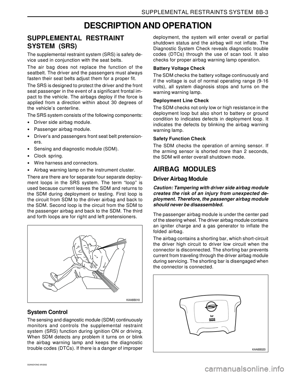
The passenger airbag module is under the center pad
of the steering wheel. The driver airbag module contains
an igniter charge and a gas generator to inflate the
folded airbag.
The airbag contains a shorting bar, which short-circuit
the driver high circuit to driver low circuit when the
connector is disconnected. The shorting bar prevents
current from traveling through the driver airbag module
during servicing. The shorting bar is disengaged when
the connector is connected.
System Control
The sensing and diagnostic module (SDM) continuously
monitors and controls the supplemental restraint
system (SRS) function during ignition ON or driving.
When SDM detects any problem it turns on or blink
the airbag warning lamp and keeps the diagnostic
trouble codes (DTCs). If there is a danger of improper
KAA8B020
Page 1590 of 2053
SUPPLEMENTAL RESTRAINTS SYSTEM 8B-5
SSANGYONG MY2002
KAA8B060
AIRBAG WARNING LAMP
The instrument cluster contains an airbag warning indi-
cator bulb to verify the operation of the airbag indicator
and sensing and diagnostic module (SDM). The SDM
performs a start-up test when the ignition is turned ON
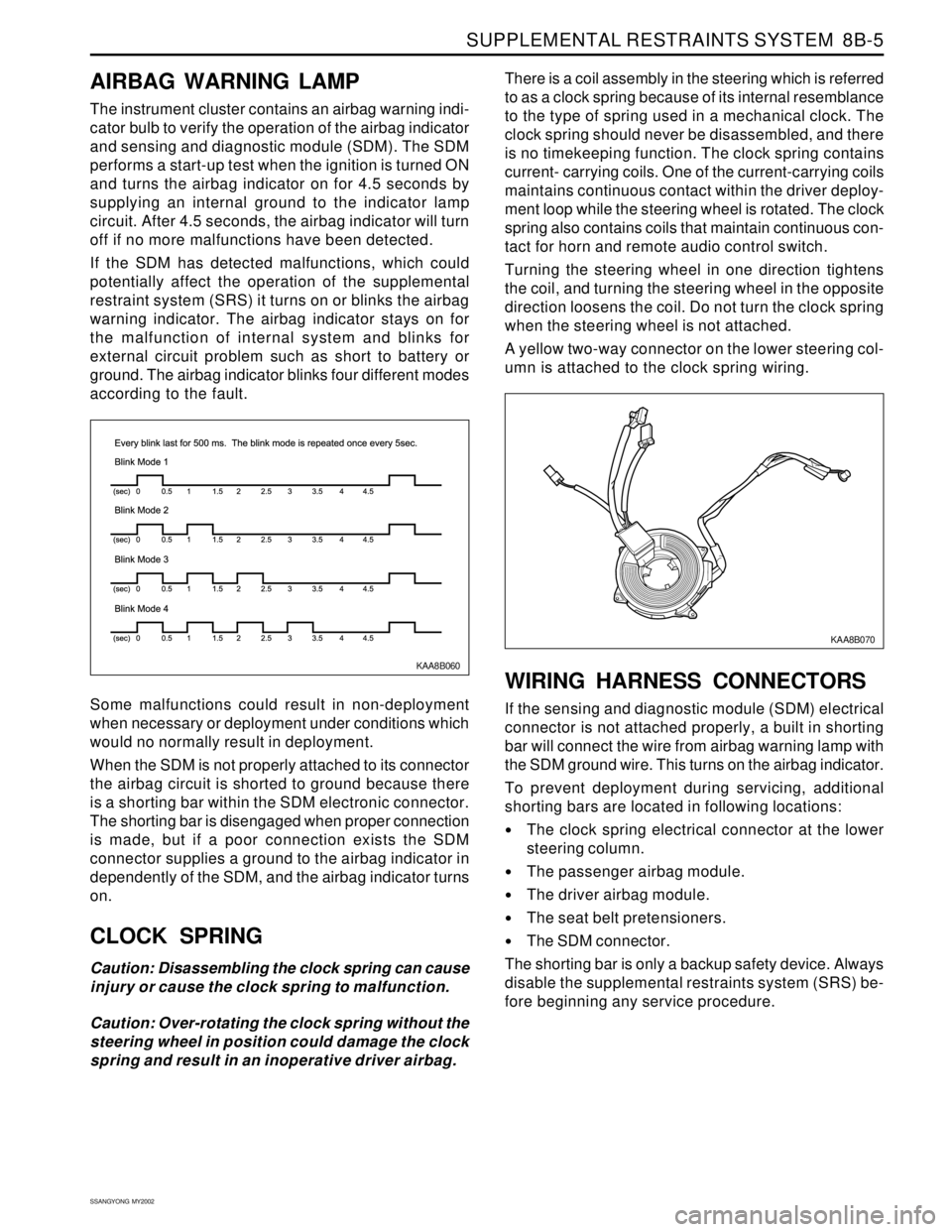
and turns the airbag indicator on for 4.5 seconds by
supplying an internal ground to the indicator lamp
circuit. After 4.5 seconds, the airbag indicator will turn
off if no more malfunctions have been detected.
If the SDM has detected malfunctions, which could
potentially affect the operation of the supplemental
restraint system (SRS) it turns on or blinks the airbag
warning indicator. The airbag indicator stays on for
the malfunction of internal system and blinks for
external circuit problem such as short to battery or
ground. The airbag indicator blinks four different modes
according to the fault.
Some malfunctions could result in non-deployment
when necessary or deployment under conditions which
would no normally result in deployment.
When the SDM is not properly attached to its connector
the airbag circuit is shorted to ground because there
is a shorting bar within the SDM electronic connector.
The shorting bar is disengaged when proper connection
is made, but if a poor connection exists the SDM
connector supplies a ground to the airbag indicator in
dependently of the SDM, and the airbag indicator turns
on.
CLOCK SPRING
Caution: Disassembling the clock spring can cause
injury or cause the clock spring to malfunction.
Caution: Over-rotating the clock spring without the
steering wheel in position could damage the clock
spring and result in an inoperative driver airbag.There is a coil assembly in the steering which is referred
to as a clock spring because of its internal resemblance
to the type of spring used in a mechanical clock. The
clock spring should never be disassembled, and there
is no timekeeping function. The clock spring contains
current- carrying coils. One of the current-carrying coils
maintains continuous contact within the driver deploy-
ment loop while the steering wheel is rotated. The clock
spring also contains coils that maintain continuous con-
tact for horn and remote audio control switch.
Turning the steering wheel in one direction tightens
the coil, and turning the steering wheel in the opposite
direction loosens the coil. Do not turn the clock spring
when the steering wheel is not attached.
A yellow two-way connector on the lower steering col-
umn is attached to the clock spring wiring.
WIRING HARNESS CONNECTORS
If the sensing and diagnostic module (SDM) electrical
connector is not attached properly, a built in shorting
bar will connect the wire from airbag warning lamp with
the SDM ground wire. This turns on the airbag indicator.
To prevent deployment during servicing, additional
shorting bars are located in following locations:
The clock spring electrical connector at the lower
steering column.
The passenger airbag module.
The driver airbag module.
The seat belt pretensioners.
The SDM connector.
The shorting bar is only a backup safety device. Always
disable the supplemental restraints system (SRS) be-
fore beginning any service procedure.
KAA8B070
Page 1636 of 2053
SSANGYONG MY2002
8B-54 SUPPLEMENTAL RESTRAINTS SYSTEM
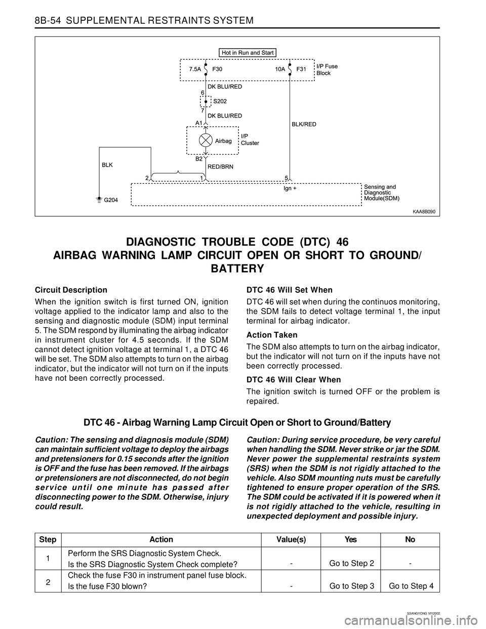
Circuit Description
When the ignition switch is first turned ON, ignition
voltage applied to the indicator lamp and also to the
sensing and diagnostic module (SDM) input terminal
5. The SDM respond by illuminating the airbag indicator
in instrument cluster for 4.5 seconds. If the SDM
cannot detect ignition voltage at terminal 1, a DTC 46
will be set. The SDM also attempts to turn on the airbag
indicator, but the indicator will not turn on if the inputs
have not been correctly processed.
DIAGNOSTIC TROUBLE CODE (DTC) 46
AIRBAG WARNING LAMP CIRCUIT OPEN OR SHORT TO GROUND/
BATTERY
DTC 46 Will Set When
DTC 46 will set when during the continuos monitoring,
the SDM fails to detect voltage terminal 1, the input
terminal for airbag indicator.
Action Taken
The SDM also attempts to turn on the airbag indicator,
but the indicator will not turn on if the inputs have not
been correctly processed.
DTC 46 Will Clear When
The ignition switch is turned OFF or the problem is
repaired.
KAA8B090
DTC 46 - Airbag Warning Lamp Circuit Open or Short to Ground/Battery
Caution: The sensing and diagnosis module (SDM)
can maintain sufficient voltage to deploy the airbags
and pretensioners for 0.15 seconds after the ignition
is OFF and the fuse has been removed. If the airbags
or pretensioners are not disconnected, do not begin
service until one minute has passed after
disconnecting power to the SDM. Otherwise, injury
could result.Caution: During service procedure, be very careful
when handling the SDM. Never strike or jar the SDM.
Never power the supplemental restraints system
(SRS) when the SDM is not rigidly attached to the
vehicle. Also SDM mounting nuts must be carefully
tightened to ensure proper operation of the SRS.
The SDM could be activated if it is powered when it
is not rigidly attached to the vehicle, resulting in
unexpected deployment and possible injury.
Perform the SRS Diagnostic System Check.
Is the SRS Diagnostic System Check complete?
Check the fuse F30 in instrument panel fuse block.
Is the fuse F30 blown?
StepAction Value(s) Yes No
1
- Go to Step 3 Go to Step 4 2
- Go to Step 2 -
Page 1637 of 2053
SUPPLEMENTAL RESTRAINTS SYSTEM 8B-55
SSANGYONG MY2002
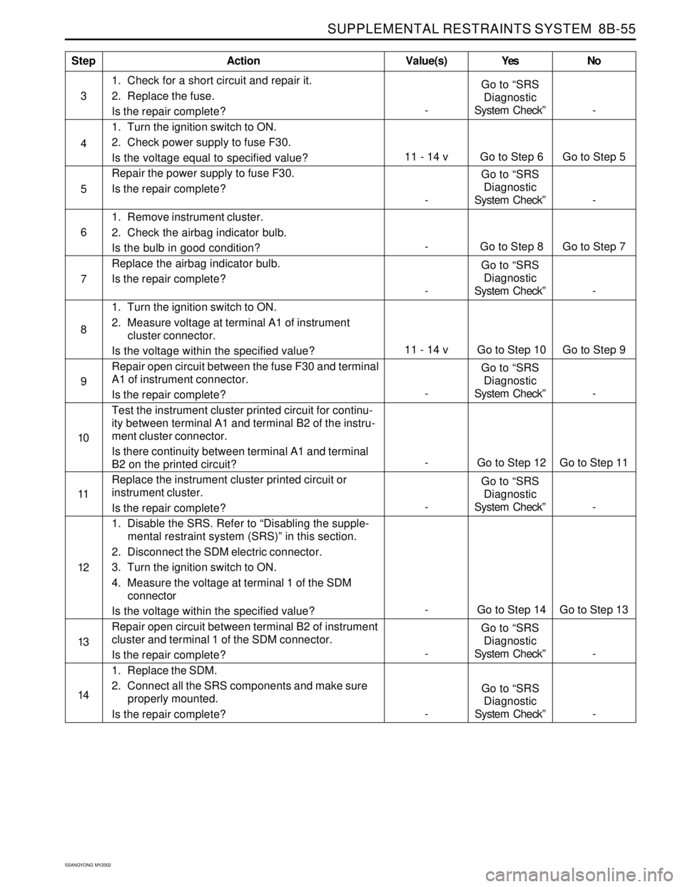
1. Check for a short circuit and repair it.
2. Replace the fuse.
Is the repair complete?
1. Turn the ignition switch to ON.
2. Check power supply to fuse F30.
Is the voltage equal to specified value?
Repair the power supply to fuse F30.
Is the repair complete?
1. Remove instrument cluster.
2. Check the airbag indicator bulb.
Is the bulb in good condition?
Replace the airbag indicator bulb.
Is the repair complete?
1. Turn the ignition switch to ON.
2. Measure voltage at terminal A1 of instrument
cluster connector.
Is the voltage within the specified value?
Repair open circuit between the fuse F30 and terminal
A1 of instrument connector.
Is the repair complete?
Test the instrument cluster printed circuit for continu-
ity between terminal A1 and terminal B2 of the instru-
ment cluster connector.
Is there continuity between terminal A1 and terminal
B2 on the printed circuit?
Replace the instrument cluster printed circuit or
instrument cluster.
Is the repair complete?
1. Disable the SRS. Refer to “Disabling the supple-
mental restraint system (SRS)” in this section.
2. Disconnect the SDM electric connector.
3. Turn the ignition switch to ON.
4. Measure the voltage at terminal 1 of the SDM
connector
Is the voltage within the specified value?
Repair open circuit between terminal B2 of instrument
cluster and terminal 1 of the SDM connector.
Is the repair complete?
1. Replace the SDM.
2. Connect all the SRS components and make sure
properly mounted.
Is the repair complete?
StepAction Value(s) Yes No
4
6
7
8
11 - 14 v Go to Step 6 Go to Step 5
5
-Go to “SRS
Diagnostic
System Check” -
- Go to Step 8 Go to Step 7
-Go to “SRS
Diagnostic
System Check” -
9
10
11
12
-Go to “SRS
Diagnostic
System Check” - 3
11 - 14 v Go to Step 10 Go to Step 9
-Go to “SRS
Diagnostic
System Check” -
13
- Go to Step 12 Go to Step 11
- Go to Step 14 Go to Step 13
-Go to “SRS
Diagnostic
System Check” -
-Go to “SRS
Diagnostic
System Check” - 14
-Go to “SRS
Diagnostic
System Check” -
Page 1638 of 2053
SSANGYONG MY2002
8B-56 SUPPLEMENTAL RESTRAINTS SYSTEM
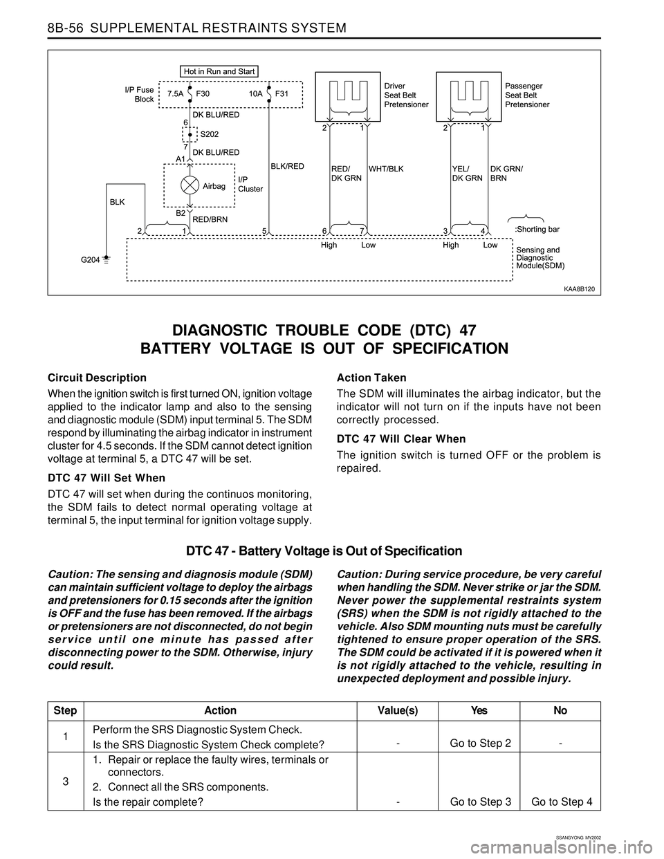
Circuit Description
When the ignition switch is first turned ON, ignition voltage
applied to the indicator lamp and also to the sensing
and diagnostic module (SDM) input terminal 5. The SDM
respond by illuminating the airbag indicator in instrument
cluster for 4.5 seconds. If the SDM cannot detect ignition
voltage at terminal 5, a DTC 47 will be set.
DTC 47 Will Set When
DTC 47 will set when during the continuos monitoring,
the SDM fails to detect normal operating voltage at
terminal 5, the input terminal for ignition voltage supply.
DIAGNOSTIC TROUBLE CODE (DTC) 47
BATTERY VOLTAGE IS OUT OF SPECIFICATION
Action Taken
The SDM will illuminates the airbag indicator, but the
indicator will not turn on if the inputs have not been
correctly processed.
DTC 47 Will Clear When
The ignition switch is turned OFF or the problem is
repaired.
KAA8B120
DTC 47 - Battery Voltage is Out of Specification
Caution: The sensing and diagnosis module (SDM)
can maintain sufficient voltage to deploy the airbags
and pretensioners for 0.15 seconds after the ignition
is OFF and the fuse has been removed. If the airbags
or pretensioners are not disconnected, do not begin
service until one minute has passed after
disconnecting power to the SDM. Otherwise, injury
could result.Caution: During service procedure, be very careful
when handling the SDM. Never strike or jar the SDM.
Never power the supplemental restraints system
(SRS) when the SDM is not rigidly attached to the
vehicle. Also SDM mounting nuts must be carefully
tightened to ensure proper operation of the SRS.
The SDM could be activated if it is powered when it
is not rigidly attached to the vehicle, resulting in
unexpected deployment and possible injury.
Perform the SRS Diagnostic System Check.
Is the SRS Diagnostic System Check complete?
1. Repair or replace the faulty wires, terminals or
connectors.
2. Connect all the SRS components.
Is the repair complete?
StepAction Value(s) Yes No
1
-
Go to Step 3 Go to Step 4 3
- Go to Step 2 -
Page 1676 of 2053
SSANGYONG MY2002
9B-2 LIGHTING SYSTEM
DESCRIPTION AND OPERATION
HEAD LAMPS - ON REMINDER
When the headlamp switch is in the headlamps-on or
parkinglamps-on positions, voltage is applied to the
chime module. With the headlamp switch on and the
driver’s side door open, the module loses voltage. The
module senses this change. If voltage is still available,
it is applied to sound the chime. The chime can be
turned off by turning the headlamp switch off or closing
the driver’s side door. To replace the chime module,
refer to Section 9E, Instrumentation / Driver Information.
HEAD LAMPS
The headlamps are controlled by the multifunction lever
on the left side of the steering column. They will come
on with the ignition switch in on position. Turning the
headlamp switch to the first position turns on the
parking lamps, the license plate lamps, and the
instrument panel illumination. Turning the switch to the
second position turns on all of the previous lamps and
the headlamps. Turning the switch off turns off all the
lamps.
The headlamps high beam and low beams are also
controlled by this lever. When the headlamps are on,
pushing the lever away from the driver until the switch
clicks changes the lamp from low beam to high beam.
An indicator lamp on the instrument cluster assembly
will come on when the high beam headlamps are on.
To return the headlamps to low beams, pull the lever
toward the driver.
The headlamps must be aimed for proper illumination
of the road. Headlamp aim should be checked
whenever a new headlamp assembly is installed or
when service or repairs to the front end may have
disturbed the headlamp assembly or its mountings.
DAYTIME RUNNING LAMPS
The daytime running lamps (DRL) will illuminate under
the following conditions:
The ignition is ON.
The light switch is OFF.
The parking brake is released.
When the head lamps are on, the DRL will turn off.
To turn the DRL off when idling, apply the parking
brake.
PARKING AND TURN SIGNAL
LAMPS
The parking lamps can be turned on by turning the
headlamp switch to the first position. The parking lamps
can be turned off by turning the switch off.
When the turn signals are activated, the appropriate
turn signal lamps flash to signal a turn. The front, the
rear, work only when the ignition is on.
The front and rear turn signals are controlled by the
multifunction lever on the left side of the steering
column. Moving the lever all the way up or down past
the detent will turn on the turn signals. When the turn
is complete, the lever will automatically be release,
and the front and the rear turn signals will stop flashing.
For changing lanes or shallow turns in which the steering
wheel does not turn far enough to cancel the signal,
move the signal to the first detent and hold it there.
The turn signal will cancel when the lever is released.
FOG LAMPS
The fog lamp switch is located in multifunction lever
on the right side of steering column. To use the fog
lamps, first turn on the parking lamps. Then, turning
the fog lamps switch on position. The indicator light in
the instrument cluster will illuminate to indicate that
the fog lamps are on. Turning the switch again to turn
off the fog lamps. The indicator light will then go off.
The fog lamps must be aimed for proper illumination
of the road. Fog lamp aim should be checked when a
new bulb is installed or if service or repairs to the front
end may have disturbed the fog lamp assembly or its
mountings.
REAR COMBINATION LAMPS
The taillamps, stoplamps, backup lamps and turn
signals are one assembly.
Turning on either the headlamps or the parking lamps
will also turn on the taillamps. When the brake pedal
is pushed, the taillamps will glow more brightly to serve
as stop lamps.
CENTER HIGH-MOUNTED STOP
LAMP
The center high-mounted stoplamp is on the tail gate
and will come on when the brake pedal is pressed.