Page 849 of 4133
45 Getting started
Driving
Seat belt height adjustment
Seat belt height can be adjusted for the fol-
lowing seats:�
Driver’s seat
�
Passenger seat
�
Outer rear seats
Adjust seat belt so that the shoulder por-
tion is located as close as possible to the
middle of the shoulder (it should not touch
the neck or pass under the arm).1Release buttonAdjusting seat belt higher
�
Slide belt outlet upward.
The belt outlet engages in various posi-
tions.
Adjusting seat belt lower
�
Press and hold release button1.
�
Slide belt outlet in desired position and
let go of release button1.
Page 863 of 4133

59 Safety and Security
Occupant safety
AirbagsWarning!
G
Airbags are designed to reduce the potential
of injury and fatality in certain frontal (front
airbags) impacts, or side (side impact and
head protection window curtain airbags) im-
pacts which may cause significant injuries.
However, no system available today can to-
tally eliminate injuries and fatalities.
The activation of the SRS temporarily releas-
es a small amount of dust from the airbags.
This dust, however, is neither injurious to
your health, nor does it indicate a fire in the
vehicle. The dust might cause some tempo-
rary breathing difficulty for people with asth-
ma or other breathing trouble. To avoid this,
you may wish to get out of the vehicle as
soon as it is safe to do so. If you have any
breathing difficulty but cannot get out of the
vehicle after the airbag inflates, then get
fresh air by opening a window or door.
Warning!
G
To reduce the risk of injury when the front
airbags inflate, it is very important for the
driver and passenger to always be in a prop-
erly seated position and to wear your seat
belt.
For maximum protection in the event of a
collision always be in normal seated position
with your back against the backrest. Fasten
your seat belt and ensure that it is properly
positioned on your body (
�page 42).
Since the airbag inflates with considerable
speed and force, a proper seating and hands
on steering wheel position will help to keep
you at a safe distance from the airbag. Oc-
cupants who are unbelted, out of position or
too close to the airbag can be seriously in-
jured by an airbag as it inflates with great
force in the blink of an eye:
�
Sit properly belted in an upright position
with your back against the seat back-
rest.
�
Adjust the driver seat as far as possible
rearward, still permitting proper opera-
tion of vehicle controls. The distance
from the center of the driver’s breast-
bone to the center of the airbag cover on
the steering wheel must be at least ten
inches (25 cm) or more. You should be
able to accomplish this by a combina-
tion of adjustments to the seat and
steering wheel. If you have any prob-
lems, please see your authorized
Mercedes-Benz Light Truck Center.
�
Airbags and emergency tensioning de-
vices (ETDs) are designed to function on
a one-time only basis. An airbag or ETD
that was activated must be replaced.
�
Do not lean with your head or chest
close to the steering wheel or dash-
board.
�
Keep hands on the outside of steering
wheel rim. Placing hands and arms in-
side the rim can increase the risk and
potential severity of hand / arm injury
when driver front airbag inflates.
��
Page 899 of 4133
95 Controls in detail
Seats
�Seats
Information on seat adjustment can be
found in the “Getting started” section
(�page 34).
Removing and installing front seat
head restraints
Information on head restraint adjustment
can be found in the “Getting started” sec-
tion (
�page 34).Front seat head restraints
Removing head restraints
�
Pull head restraint to its highest
position.
�
Push button1 and pull out head
restraint.
Warning!
G
For your protection, drive only with properly
positioned head restraints.
Adjust head restraint so that the head re-
straint supports the back of the head at eye
level. This will reduce the potential for injury
to the head and neck in the event of an
accident or similar situation.
Do not drive the vehicle without the seat
head restraints. Head restraints are intend-
ed to help reduce injuries during an acci-
dent.
Do not interchange head restraints from
front and rear seat.
Page 910 of 4133

106 Controls in detailMemory function*Storing parking position�
Stop the vehicle.
�
Switch on ignition (if not already on).
�
Press button2.
The passenger-side exterior rear view
mirror is selected.
�
Adjust the exterior rear view mirror
with button3 so that you see the rear
wheel and the road curb.
�
Press memory button2 (
�page 105).
�
Within three seconds, press bottom of
adjustment button3.
The parking position is stored if the
mirror does not move.
Storing positions in memory�
Adjust the seat (
�page 37) and exteri-
or rear view mirrors (�page 40) to the
desired position.
�
Push memory button2 (
�page 105).
�
Release memory button and press one
of the position buttons1 within three
seconds.
All the settings are stored at the select-
ed position.
Recalling positions from memory�
Press and hold one of the position
buttons1 until seat and rear view mir-
rors have fully moved to the stored po-
sitions.
iIf the mirror does move, repeat the
above steps. After the setting is stored
you can move the mirror again.
The selected position will be stored rel-
ative to the position button1
(�page 105) pressed.
!Do not operate the power seats using
the memory button if the seat backrest
is in an excessively reclined position.
Doing so could cause damage to front
or rear seats.iReleasing the button immediately
stops movement to the stored posi-
tions.
Page 1076 of 4133

272 Practical hintsReplacing bulbs�
Insert reflector from the left so that it
engages on the right.
�
Position tabs of cover in slots and rein-
stall cover until properly seated.
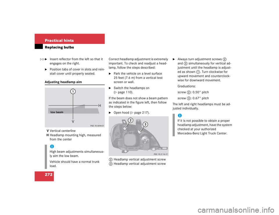
Adjusting headlamp aim
VVertical centerline
HHeadlamp mounting high, measured
from the centerCorrect headlamp adjustment is extremely
important. To check and readjust a head-
lamp, follow the steps described:
�
Park the vehicle on a level surface
25 feet (7.6 m) from a vertical test
screen or wall.
�
Switch the headlamps on
(�page 110).
If the beam does not show a beam pattern
as indicated in the figure left, then follow
the steps below:
�
Open hood (
�page 217).
2Headlamp vertical adjustment screw
3Headlamp vertical adjustment screw
�
Always turn adjustment screws2
and3 simultaneously for vertical ad-
justment until the headlamp is adjust-
ed as shown1. Turn clockwise for
upward movement and counterclock-
wise for downward movement.
Graduations:
screw2: 0.50° pitch
screw3: 0.67° pitch
The left and right headlamps must be ad-
justed individually.
iHigh beam adjustments simultaneous-
ly aim the low beam.
Vehicle should have a normal trunk
load.
iIf it is not possible to obtain a proper
headlamp adjustment, have the system
checked at your authorized
Mercedes-Benz Light Truck Center.
��
Page 1121 of 4133

317 Index
A
ABS 25, 76, 311
ABS control 76
LOW RANGE mode 77
Malfunction indicator lamp 242
Warning lamp 242
Accelerator position, automatic
transmission 123
Accident
In case of 52
Activating
Air circulation mode 139
Air recirculation mode 139
Anti-theft alarm system 83
Automatic climate control 135
ESP 82
Exterior headlamps 48
Hazard warning flasher 112
Headlamps 48
High beams 110
Ignition 33Immobilizer 54, 83
Rear passenger compartment ventila-
tion and climate control 141
Rear window defroster 133
Rear window wiper 51
Residual heat 140
Seat heater* 98
Tow-away alarm 85
Warning indicators (Parktronic*) 155
Windshield wipers 50
Activating automatic central locking 93
Adding
Coolant 223
Engine oil 221
Additional turn signals 266
Adjustable steering column
Indicator lamp 253
Adjusting 34
Backrest tilt 36, 38
Exterior rear view mirror 40
Head restraint height 36, 38Head restraint tilt 37, 39
Headlamp aim 272
Instrument cluster illumination 116
Manual seat 35
Mirrors 40
Power seats* 37
Seat cushion tilt 38
Seat fore and aft 35
Seat fore and aft adjustment 37
Seat height 36, 38
Seats 34
Steering wheel 39
Adjusting air distribution
Automatic climate control 137
Adjusting air volume
Automatic climate control 137
Air conditioner (cooling)
Turning on 139
Air conditioning
Cooling 139
Page 1126 of 4133

322 IndexCoolant 222, 304
Adding 223
Anticorrosion/antifreeze
quantity 304
Checking level 222
Indicator lamp 249
Temperature 213
Temperature gauge 117
Coolant level
Checking 215, 222
Crossing obstacles 204
Cruise control 150, 311
Canceling 151
Driving downhill 151
Driving uphill 151
Fine adjustment 152
LOW RANGE mode 152
Saving current speed 151
Setting speeds 152
Cruise control lever 150Cup holder 166
Cleaning 238
In front seat armrest 167
In instrument panel 166
In rear centerconsole 167
Customer Assistance Center (CAC) 311
D
Daytime running lamp mode 109
Deactivating
Air conditioning (cooling) 139
Air recirculation mode 139
Alarm 84
Anti-theft alarm system 84
Automatic climate control 135, 137
Cruise control 151
Defrost 138
Engine 54
ESP 81
Front fog lamps, rear fog lamp 111
Hazard warning flasher 112
Headlamps 54
Immobilizer 83
Rear passenger compartment ventila-
tion and climate control 141
Rear window defroster 133Residual heat 140
Seat heater* 98
Tow-away alarm 85
Tow-away alarm (vehicles with trip
computer*) 85
Tow-away alarm (vehicles without trip
computer*) 86
Deactivating automatic central
locking 93
Deep water see Standing water 200
Defogging
Windshield 138
Defrosting 138
Difficulties
While driving see Problems while
driving 51
With starting 47
Direction of rotation (tires) 227
Discharged battery
Jump starting 281
Disconnecting
Vehicle battery 279
Display in the speedometer 117
Page 1129 of 4133

325 Index
F
Fastening the seat belts 42
Fine adjustment
Cruise control 152
First aid kit 257
Flat tire 274
Lowering the vehicle 276
Mounting the spare wheel 274
Preparing the vehicle 274
Spare wheel 259
Flexible Service System (FSS) 232, 312
Fluid level
Automatic transmission 222
Fog lamp, rear 267
Fog lamps 111
Replacing bulbs 266
Fog lamps, front
Replacing bulbs 267
Switching on 111
Folding
Exterior mirrors 128
Folding electrically
Exterior rear view mirrors
1284-ETS 25, 79
Indicator lamp 252
LOW RANGE mode 80
Malfunction indicator lamp 252
Warning lamp 251
Front airbags 63
Front fog lamps
Indicator lamp 253
Front lamps
Replacing bulbs 266, 268
Front towing eyes 285
FSS (Flexible Service System) 232, 312
Fuel 215
Additives 303
Fuel reserve warning lamp 252
Gasoline additives 303
Premium unleaded gasoline 215,
303
Requirements 303
Reserve warning 25
Fuel additives 303
Fuel filler flap 214
Locking 214
Opening 263
Unlocking 214
Fuel requirements 303Fuel tank
Filler flap 214
Fuels, coolants, lubricants etc. 300
Functions
Trip computer* 186
Fuse box 287, 288
Fuse chart 287
Fuses 287
F us e box i n engi ne com p art me nt 2 87
Fuse box in passenger footwell 288
Fuse chart 287
Fuse extractor 287
Spare fuses 287
G
Garage door opener 29, 180
Erasing in remote control 185
Gasoline see Fuel 215
Gasoline additives 303
Gauge for
Coolant temperature 25
Fuel 25
Outside temperature 25