1997 MERCEDES-BENZ ML500 seat adjustment
[x] Cancel search: seat adjustmentPage 1880 of 4133
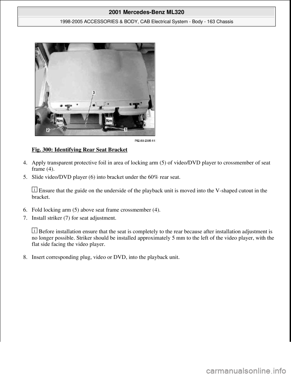
Fig. 300: Identifying Rear Seat Bracket
4. Apply transparent protective foil in area of locking arm (5) of video/DVD player to crossmember of seat
frame (4).
5. Slide video/DVD player (6) into bracket under the 60% rear seat.
Ensure that the guide on the underside of the playback unit is moved into the V-shaped cutout in the
bracket.
6. Fold locking arm (5) above seat frame crossmember (4).
7. Install striker (7) for seat adjustment.
Before installation ensure that the seat is completely to the rear because after installation adjustment is
no longer possible. Striker should be installed approximately 5 mm to the left of the video player, with the
flat side facing the video player.
8. Insert correspondin
g plug, video or DVD, into the playback unit.
2001 Mercedes-Benz ML320
1998-2005 ACCESSORIES & BODY, CAB Electrical System - Body - 163 Chassis
me
Saturday, October 02, 2010 3:30:12 PMPage 385 © 2006 Mitchell Repair Information Company, LLC.
Page 1887 of 4133
material (8)
18Plug remaining antenna
cable of FM modulator
(9) into radio
19Install radio (A2)
Remove/install radio AR82.60-P-7502EA
20Retrofit video monitor (2)
and wiring harness of
video monitor (C) With glass version of
electric sliding/tilting
roof, code 414a.AZ82.60-P-0004-02A
Except glass version
of electric sliding/ tilting
roof, code 414a.AZ82.60-P-0004-02B
21Secure upper right B-
pillar paneling Ensure that the lugs of
the seat belt height
adjustment are located
correctly in the recess
clearance of the paneling.
22Install right front handle
23Install right sun visor
Remove/install sun visor AR68.60-P-5480GH
24Install right front A-pillar
cover
Remove/install paneling
on A-pillar AR68.30-P-4050GH
25Re-secure upper area of
rubber door seal
26Route wiring harness of
video/DVD player (B),
additional interface
module (4) and wiring
harness of video monitor
(C) later Up to VIN A289564,
X754619.AZ82.60-P-0004-03A
As of VIN A289565,
X754620.AZ82.60-P-0004-03B
27Retrofit auxiliary
interface module (4) in
center console Up to VIN A289564,
X754619.AZ82.60-P-0004-04A
As of VIN A289565,
X754620.AZ82.60-P-0004-04B
28Install center console
insulating mat
29Install center console
Remove/install center
console AR68.20-P-2000GH
2001 Mercedes-Benz ML320
1998-2005 ACCESSORIES & BODY, CAB Electrical System - Body - 163 Chassis
me
Saturday, October 02, 2010 3:30:12 PMPage 392 © 2006 Mitchell Repair Information Company, LLC.
Page 1970 of 4133
AP82.10-P-8260GH
Check and correct headlamp adjustment
2.7.97
MODEL
163
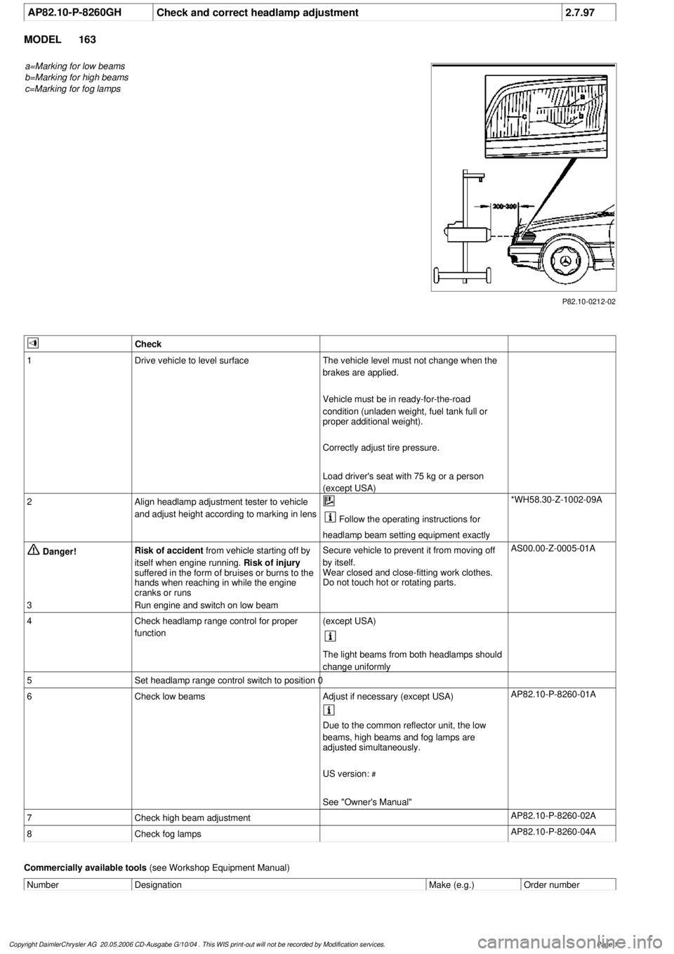
a=Marking for low beams
b=Marking for high beams
c=Marking for fog lamps
P82.10-0212-02
Check
1
Drive vehicle to level surface
The vehicle level must not change when the
brakes are applied.
Vehicle must be in ready-for-the-road
condition (unladen weight, fuel tank full or
proper additional weight).
Correctly adjust tire pressure.
Load driver's seat with 75 kg or a person
(except USA)
2
Align headlamp adjustment tester to vehicle
and adjust height according to marking in lens
Follow the operating instructions for
headlamp beam setting equipment exactly
*WH58.30-Z-1002-09A
Danger!
Risk of accident
from vehicle starting off by
itself when engine running.
Risk of injury
suffered in the form of bruises or burns to the
hands when reaching in while the engine
cranks or runs
Secure vehicle to prevent it from moving off
by itself.
Wear closed and close-fitting work clothes.
Do not touch hot or rotating parts.
AS00.00-Z-0005-01A
3
Run engine and switch on low beam
4
Check headlamp range control for proper
function
(except USA)
The light beams from both headlamps should
change uniformly
5
Set headlamp range control switch to position 0
6
Check low beams
Adjust if necessary (except USA)
AP82.10-P-8260-01A
Due to the common reflector unit, the low
beams, high beams and fog lamps are
adjusted simultaneously.
US version:
#
See "Owner's Manual"
7
Check high beam adjustment
AP82.10-P-8260-02A
8
Check fog lamps
AP82.10-P-8260-04A
Commercially available tools
(see Workshop Equipment Manual)
Number
Designation
Make (e.g.)
Order number
Copyright DaimlerChrysler AG 20.05.2006 CD-Ausgabe G/10/04 . This WIS print-out will not be recorde
d by Modification services.
Page 1
Page 2067 of 4133

GF72.29-P-2002GH
Convenience control, function
7.4.97
MODEL
163
The convenience control allows the driver to operate the electrical
seat adjustment, the power windows, the electric vent windows, the
electric outside rearview mirror as well as the electric sliding/pop-up
roof or the electric lamella sliding roof
when the ignition is switched
off.
To achieve this, the all-activity module (AAM) (N10) switches to the
corresponding loads via the convenience relay (F1k14)
circuit 30 .
As of 12.99 the vehicle is equipped with its own convenience relay for
seat adjustment (relay 1, F2k1). In addition the status of the
convenience control via CAN is transmitted to the extended activity
module (EAM, N10/1).
Conditions for control actuation
On all-activity module (AAM) (N10) configured for
I
up
to
11.99:
The convenience actuation becomes active as soon as
D
Circuit 15 ON is recognized
When circuit 15 is switched off, the convenience actuation is
deactivated after a door is opened
Otherwise
The convenience actuation is active in the following cases:
D
Circuit 15c ON
D
A front door is open
D
The remote control key is removed, however, the doors are not
yet opened
In both cases the convenience actuation remains active for 5 min.
Switch-on condition for circuit 15c
When the remote control key is inserted into the ignition lock, circuit
15c is switched on when the key is turned out of the zero position.
Circuit 15c switches off only after the remote control key is removed
from the ignition lock
Electric seat adjustment without memory,
function
GF91.29-P-0003GH
Electric seat adjustment with memory, function
as of 12.99
GF91.29-P-0002GH
Convenience control, function
for electrical seat adjustment as of 12.99
GF91.29-P-2013GK
Power windows, function
GF72.29-P-0003GH
Power tilting/sliding roof (SR), function
GF77.20-P-0001GH
Electrically adjustable outside rearview
mirrors, function
GF88.79-P-0005GH
Electric vent windows, function
GF67.39-P-1000GH
Extended activity module,
location/purpose/design
as of 12.99
GF54.21-P-4107GK
Copyright DaimlerChrysler AG 04.08.2006 CD-Ausgabe G/10/04 . This WIS print-out will not be recorde
d by Modification services.
Page 1
Page 2350 of 4133
MEASURE VALVE SETBACK TO CYLI NDER HEAD - AR05.30-P-4100-01AV
Modification notes
Test and adjustment values of cylinder head
Test and adjustment values of cylinder head
Workshop equipment
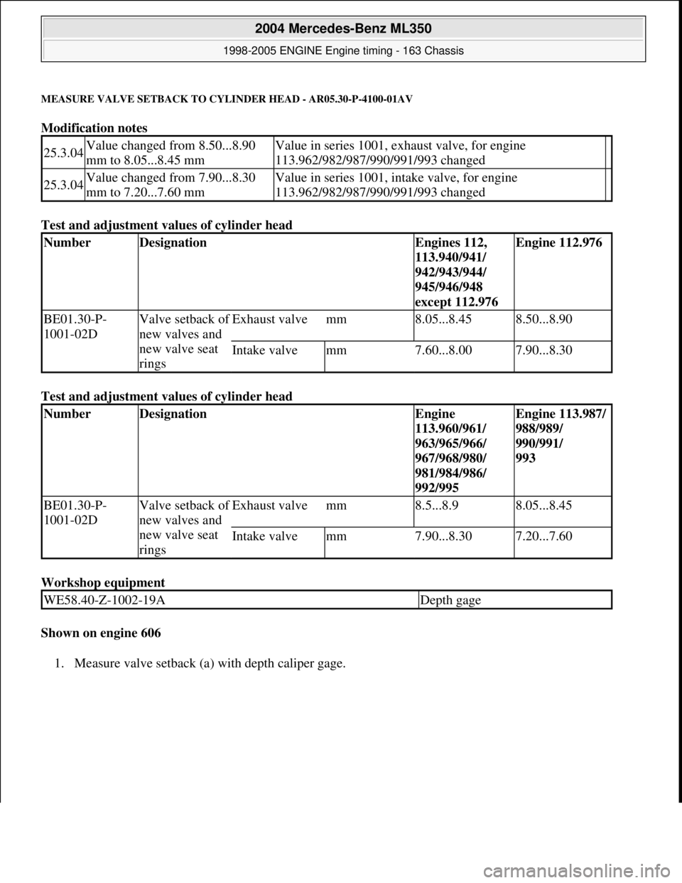
Shown on engine 606
1. Measure valve setback (a) with depth caliper
gage.
25.3.04Value changed from 8.50...8.90
mm to 8.05...8.45 mmValue in series 1001, exhaust valve, for engine
113.962/982/987/990/991/993 changed
25.3.04Value changed from 7.90...8.30
mm to 7.20...7.60 mmValue in series 1001, intake valve, for engine
113.962/982/987/990/991/993 changed
NumberDesignationEngines 112,
113.940/941/
942/943/944/
945/946/948
except 112.976Engine 112.976
BE01.30-P-
1001-02DValve setback of
new valves and
new valve seat
ringsExhaust valvemm8.05...8.458.50...8.90
Intake valvemm7.60...8.007.90...8.30
NumberDesignationEngine
113.960/961/
963/965/966/
967/968/980/
981/984/986/
992/995Engine 113.987/
988/989/
990/991/
993
BE01.30-P-
1001-02DValve setback of
new valves and
new valve seat
ringsExhaust valvemm8.5...8.98.05...8.45
Intake valvemm7.90...8.307.20...7.60
WE58.40-Z-1002-19ADepth gage
2004 Mercedes-Benz ML350
1998-2005 ENGINE Engine timing - 163 Chassis
me
Saturday, October 02, 2010 3:39:39 PMPage 109 © 2006 Mitchell Repair Information Company, LLC.
Page 2510 of 4133

AD91.29-P-1000GHZ
Electric seat adjustment (ESA) diagnosis contents
23.5.97
MODEL
163 with CODE (221b) electrically-adjustable driver's and front passenger's seat
A15.5
j
11
Electric seat adjustment diagnosis, advanced
information (ESA)
AD91.29-P-2001GH
A15.5
j
12
Electric seat adjustment diagnosis, function
check (ESA)
AD91.29-P-3000GH
A15.5
j
13
Electric seat adjustment diagnosis,
troubleshooting (ESA)
AD91.29-P-5001GH
A15.5
j
21
Electric seat adjustment diagnosis, testing
electrical system (ESA)
AD91.29-P-6002GH
Copyright DaimlerChrysler AG 14.06.2006 CD-Ausgabe G/10/04 . This WIS print-out will not be recorde
d by Modification services.
Page 1
Page 2610 of 4133

21
Detach rear brake cables
Unclip at underfloor of vehicle and
unscrew brake cable holder on right and left
at frame.
22.1
Unbolt check strap of rear axle carrier from
underfloor of vehicle
As of VIN A145273, X708319.
23
Remove left rear stone shield
24
Remove lower tensioning straps (80/2) and
loosen the upper tensioning straps
Tensioning straps are color-coded and
cannot be mixed up.
Support fuel tank using assembly jack.
*BA47.10-P-1001-01D
25
Remove longitudinal strut for tensioning
straps (80/18)
*BA47.10-P-1002-01D
26.1
Unscrew linkage for headlamp range
adjustment
at the top
If installed.
27
Unscrew nuts on bottom of the shock
absorbers at the transverse control arm
Installation:
Install new self-locking nuts.
*BA32.25-P-1001-03D
28
Unscrew rear axle carrier from floor of vehicle
and lower as far as possible
Support rear axle carrier.
Installation:
Install new self-locking bolts.
*BA35.10-P-1001-01C
29
Lower fuel tank
Support fuel tank.
30
Remove upper tensioning strap
at the rear
The tensioning strap at the top at the front.
31.1
Unclip lines from side of fuel tank
As of VIN A289565, X754620.
Installation:
The lines must not be
damaged.
32
Disconnect fuel pump electrical plug
connection
33
Disconnect fuel feed line (90/12) and fuel
return line (90/11)
Fuel lines must not be bent.
Pliers
*163589003700
34
Remove fuel tank (80)
Installation:
Ensure that the sealing
rubbers (5) seat correctly in the body floor to
prevent water entry.
Do not damage fuel lines at filler neck.
Guide filler neck with its chamfered side
(arrow) through between frame and body.
Filler neck and fuel tank cannot be separated
from each other.
35
Install in the reverse order
36.1
Dispose of fuel tank
Ony when replacing the fuel tank.
o
Disposal of fuel tanks
OS47.10-P-0001-01A
Rear axle carrier
Number
Designation
Model
Series 163
BA35.10-P-1001-01C
Self-locking bolt, rear axle carrier at front and rear
to frame floor
Nm
200
Propeller shaft
Number
Designation
Model
Series 163
BA41.10-P-1002-01C
Self-locking bolt, rear propsharft
at rear axle center section
Nm
50
Copyright DaimlerChrysler AG 28.05.2006 CD-Ausgabe G/10/04 . This WIS print-out will not be recorde
d by Modification services.
Page 3
Page 3055 of 4133
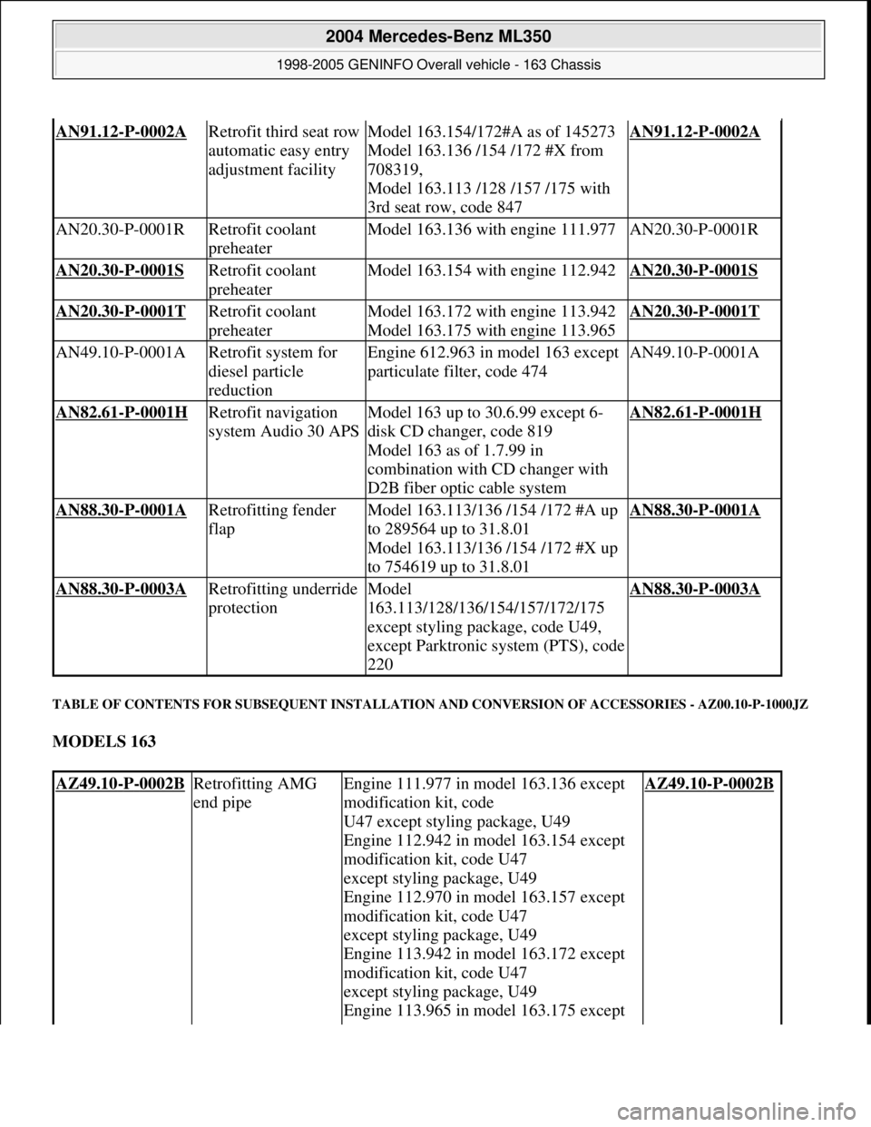
TABLE OF CONTENTS FOR SUBSEQUENT INSTALLATION AND CONVERSION OF ACCESSORIES - AZ00.10-P-1000JZ
MODELS 163
AN91.12-P-0002A Retrofit third seat row
automatic easy entry
adjustment facilityModel 163.154/172#A as of 145273
Model 163.136 /154 /172 #X from
708319,
Model 163.113 /128 /157 /175 with
3rd seat row, code 847AN91.12-P-0002A
AN20.30-P-0001RRetrofit coolant
preheaterModel 163.136 with engine 111.977AN20.30-P-0001R
AN20.30-P-0001S Retrofit coolant
preheaterModel 163.154 with engine 112.942AN20.30-P-0001S
AN20.30-P-0001T Retrofit coolant
preheaterModel 163.172 with engine 113.942
Model 163.175 with engine 113.965AN20.30-P-0001T
AN49.10-P-0001ARetrofit system for
diesel particle
reductionEngine 612.963 in model 163 except
particulate filter, code 474AN49.10-P-0001A
AN82.61-P-0001H Retrofit navigation
system Audio 30 APSModel 163 up to 30.6.99 except 6-
disk CD changer, code 819
Model 163 as of 1.7.99 in
combination with CD changer with
D2B fiber optic cable systemAN82.61-P-0001H
AN88.30-P-0001A Retrofitting fender
flapModel 163.113/136 /154 /172 #A up
to 289564 up to 31.8.01
Model 163.113/136 /154 /172 #X up
to 754619 up to 31.8.01AN88.30-P-0001A
AN88.30-P-0003A Retrofitting underride
protectionModel
163.113/128/136/154/157/172/175
except styling package, code U49,
except Parktronic system (PTS), code
220AN88.30-P-0003A
AZ49.10-P-0002B Retrofitting AMG
end pipeEngine 111.977 in model 163.136 except
modification kit, code
U47 except styling package, U49
Engine 112.942 in model 163.154 except
modification kit, code U47
except styling package, U49
Engine 112.970 in model 163.157 except
modification kit, code U47
except styling package, U49
Engine 113.942 in model 163.172 except
modification kit, code U47
except styling package, U49
Engine 113.965 in model 163.175 except AZ49.10-P-0002B
2004 Mercedes-Benz ML350
1998-2005 GENINFO Overall vehicle - 163 Chassis
me
Saturday, October 02, 2010 3:47:52 PMPage 410 © 2006 Mitchell Repair Information Company, LLC.