Page 3830 of 4133
SI91.12-P-0001GH
Service Information: Bowden cables for rear seat
30.5.03
MODELS
163.136 /154 /172 as of 1.9.99,
163.113 /128 /157 /174 /175
40 % rear seat
The Bowden cables for vertical and horizontal adjustment at the
40 % rear seat now can be individually replaced. The new routing
assignment must be observed when replacing the Bowden cables.
The connection at the release handle and at the rear seat support
remain the same.
P91.12-2598-11
1
Cable, vertical adjustment
2
Cable, horizontal adjustment
3
Clip
4
Rubber straps
f
Remove and install cables for rear seat
adjustment
Models 163.136 /154 /172 as of 1.9.99,
163.113 /128 /157 /174 /175
40 % rear seat
AR91.12-P-1130GH
Parts ordering notes
Part no.
Designation
Quantity
163 920 04 64 38
Cable, horizontal adjustment
1
163 920 12 80
Cable, vertical adjustment
1
000 995 18 14
Clip
1
Copyright DaimlerChrysler AG 14.06.2006 CD-Ausgabe G/10/04 . This WIS print-out will not be recorde
d by Modification services.
Page 1
Page 3934 of 4133

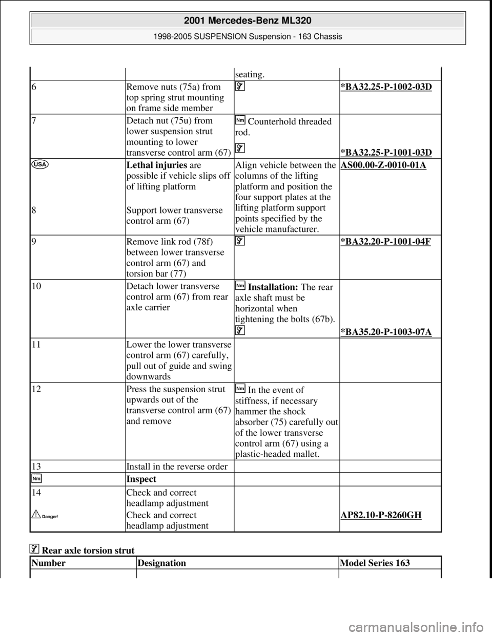
Rear axle torsion strut
seating.
6Remove nuts (75a) from
top spring strut mounting
on frame side member *BA32.25-P-1002-03D
7Detach nut (75u) from
lower suspension strut
mounting to lower
transverse control arm (67) Counterhold threaded
rod.
*BA32.25-P-1001-03D
Lethal injuries are
possible if vehicle slips off
of lifting platformAlign vehicle between the
columns of the lifting
platform and position the
four support plates at the
lifting platform support
points specified by the
vehicle manufacturer.AS00.00-Z-0010-01A
8Support lower transverse
control arm (67)
9Remove link rod (78f)
between lower transverse
control arm (67) and
torsion bar (77) *BA32.20-P-1001-04F
10Detach lower transverse
control arm (67) from rear
axle carrier Installation: The rear
axle shaft must be
horizontal when
tightening the bolts (67b).
*BA35.20-P-1003-07A
11Lower the lower transverse
control arm (67) carefully,
pull out of guide and swing
downwards
12Press the suspension strut
upwards out of the
transverse control arm (67)
and remove In the event of
stiffness, if necessary
hammer the shock
absorber (75) carefully out
of the lower transverse
control arm (67) using a
plastic-headed mallet.
13Install in the reverse order
Inspect
14Check and correct
headlamp adjustment
Check and correct
headlamp adjustment AP82.10-P-8260GH
NumberDesignationModel Series 163
2001 Mercedes-Benz ML320
1998-2005 SUSPENSION Suspension - 163 Chassis
me
Saturday, October 02, 2010 3:37:36 PMPage 26 © 2006 Mitchell Repair Information Company, LLC.
Page 3983 of 4133

10
Remove edge guard for tilting/sliding roof
cutout
11
Release upper right B-pillar paneling
12
Remove covers at lower rear seat
Do NOT remove center cover for lower
40% seat. Do NOT reinstall curtain on 60%
front bench seat.
f
Remove and install cover on bottom of rear
seat
AR91.12-P-1100GH
13
Release side shade at the 60% bench
Fold shade upward so that the working
area is not obstructed.
14
Remove 40% rear seat
f
Remove and install bench
AR91.12-P-1010GI
Torx bit set
*000589011000
Install
15
Retrofit central interface module (1)
AZ82.60-P-0004-01A
16
Insert antenna cable for FM modulator (6) into
vehicle antenna cable (7)
17
Cover connector with self-adhesive foamed
material (8)
18
Plug remaining antenna cable of FM
modulator (9) into radio
19
Install radio (A2)
f
Remove/install radio
AR82.60-P-7502EA
20
Retrofit video monitor (2) and wiring harness
of video monitor (C)
With
glass version of electric sliding/tilting
roof, code 414a.
AZ82.60-P-0004-02A
Except
glass version of electric
sliding/tilting roof, code 414a.
AZ82.60-P-0004-02B
21
Secure upper right B-pillar paneling
Ensure that the lugs of the seat belt height
adjustment are located correctly in the recess
clearance of the paneling.
22
Install right front handle
23
Install right sun visor
f
Remove/install sun visor
AR68.60-P-5480GH
24
Install right front A-pillar cover
f
Remove/install paneling on A-pillar
AR68.30-P-4050GH
25
Re-secure upper area of rubber door seal
26
Route wiring harness of video/DVD player
(B), additional interface module (4) and wiring
harness of video monitor (C) later
Up to VIN A289564, X754619.
AZ82.60-P-0004-03A
As of VIN A289565, X754620.
AZ82.60-P-0004-03B
27
Retrofit auxiliary interface module (4) in
center console
Up to VIN A289564, X754619.
AZ82.60-P-0004-04A
As of VIN A289565, X754620.
AZ82.60-P-0004-04B
28
Install center console insulating mat
29
Install center console
f
Remove/install center console
AR68.20-P-2000GH
30.1
Plug in plug of additional interface module
and secure the wiring harness of the
additional interface module (10) to the clip
(11) together with the wiring harness of the
rear power windows in the center console
Up to VIN A289564, X754619.
30.2
Insert auxiliary interface module (13)
connector and route between center console
mount (14) and center console.
As of VIN A289565, X754620.
31.1
Secure auxiliary interface module plug in the
left rear corner of the ashtray housing using
self-adhesive foamed material (12)
Up to VIN A289564, X754619.
32
Open ashtray and cup holder and close to
check correct function
33
Attach side shade of the 60% bench
34.1
Retrofit video player (3)
AZ82.60-P-0004-05A
*BA91.12-P-1005-03A
*BA91.12-P-1008-03A
34.2
Retrofit DVD player
AZ82.60-P-0005-01GH
35
Install 40% rear seat
f
Remove and install bench
AR91.12-P-1010GI
Torx bit set
*000589011000
Copyright DaimlerChrysler AG 09.05.2006 CD-Ausgabe G/10/04 . This WIS print-out will not be recorde
d by Modification services.
Page 2