Page 1082 of 4133

278 Practical hintsBattery
�BatteryThe battery is located on the passenger
side of the engine compartment.
1Negative terminal
2Positive terminal
Warning!
G
Failure to follow these instructions can re-
sult in severe injury or death.
Observe all safety instructions and precau-
tions when handling automotive batteries
(�page 223).
Never lean over batteries while connecting,
you might get injured.
Battery fluid contains sulfuric acid. Do not
allow this fluid to come in contact with eyes,
skin or clothing. In case it does, immediately
flush affected area with water and seek
medical help if necessary.
A battery will also produce hydrogen gas,
which is flammable and explosive. Keep
flames or sparks away from battery, avoid
improper connection of jumper cables,
smoking etc.
!Never loosen or detach battery termi-
nal clamps while the engine is running
or the key is in the steering lock. Other-
wise the alternator and other electronic
components could be severely dam-
aged.
Have the battery checked regularly by
an authorized Mercedes-Benz Light
Truck Center.
Refer to Service Booklet for mainte-
nance intervals or contact your autho-
rized Mercedes-Benz Light Truck
Center for further information.Warning!
G
Do not place metal objects on the battery as
this could result in a short circuit.
Use leak-proof battery only to avoid the risk
of acid burns in the event of an accident.
Page 1097 of 4133
293 Technical data
Layout of poly-V-belt drive
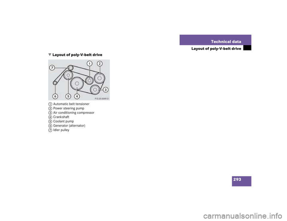
�Layout of poly-V-belt drive
1Automatic belt tensioner
2Power steering pump
3Air conditioning compressor
4Crankshaft
5Coolant pump
6Generator (alternator)
7Idler pulley
Page 1101 of 4133
297 Technical data
Electrical system
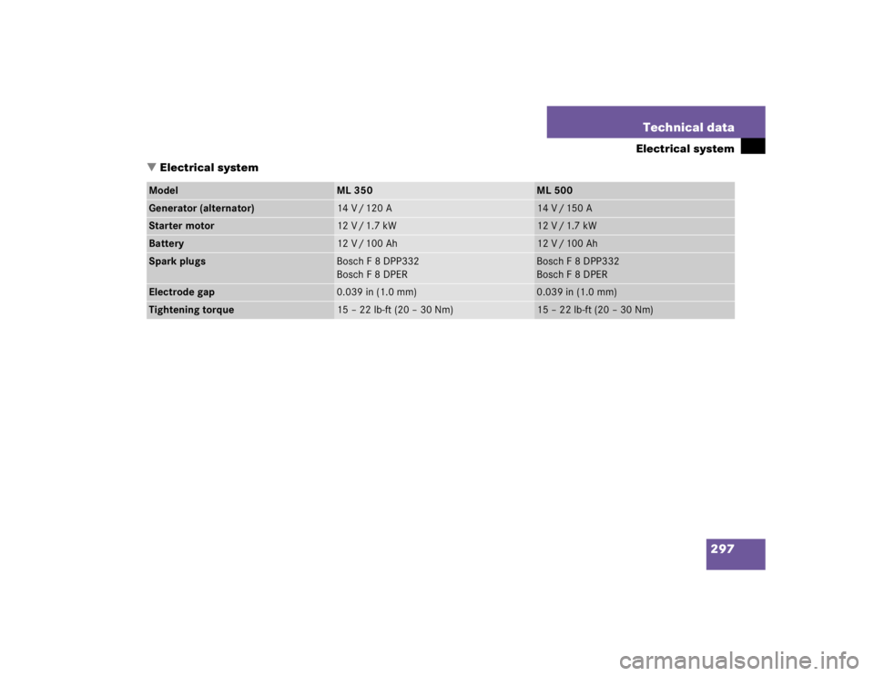
�Electrical system
Model
ML 350
ML 500
Generator (alternator)
14 V / 120 A
14 V / 150 A
Starter motor
12 V / 1.7 kW
12 V / 1.7 kW
Battery
12 V / 100 Ah
12 V / 100 Ah
Spark plugs
Bosch F 8 DPP332
Bosch F 8 DPER
Bosch F 8 DPP332
Bosch F 8 DPER
Electrode gap
0.039 in (1.0 mm)
0.039 in (1.0 mm)
Tightening torque
15 – 22 lb-ft (20 – 30 Nm)
15 – 22 lb-ft (20 – 30 Nm)
Page 1118 of 4133
 from the engine.
Power train
Collective term designating all compo-
nents used to generate and transmit")
314 Technical termsPoly-V-belt drive
Drives engine-components (alternator,
AC compressor, etc.) from the engine.
Power train
Collective term designating all compo-
nents used to generate and transmit
motive power to the drive axles, includ-
ing
�
engine
�
clutch / torque converter
�
transmission
�
transfer case
�
drive shaft
�
differential
�
axle shafts / axlesRemote Vehicle Diagnostics
Transmission of vehicle data and cur-
rent location to the Mercedes-Benz
Customer Assistance Center for sub-
scribers to Tele Aid service.
REST
(Residual engine heat utilization)
Feature that uses the engine heat
stored in the coolant to heat the vehi-
cle interior for a short time after the en-
gine has been turned off.
Restraint system
Seat belts, belt tensioner, airbags and
child seat restraint systems. As inde-
pendent systems, their protective func-
tions complement one another.RON
(R
esearch O
ctane N
umber)
The Research Octane Number for gaso-
line as determined by a standardized
method. It is an indication of a gaso-
line's ability to resist undesired detona-
tion (knocking). The average of both
the ->MON (Motor Octane Number)
and RON (Research Octane Number) is
posted at the pump, also known as
ANTI-KNOCK INDEX.
Shift lock
When the vehicle is parked, this lock
prevents the transmission selector le-
ver from being moved out of positionP
without key turned and brake pedal de-
pressed.
SRS
(S
upplemental R
estraint S
ystem)
Seat belts, emergency tensioning de-
vice and airbags. Though independent
systems, they are closely interfaced to
provide effective occupant protection.
Page 1489 of 4133

AR54.10-P-0005GH
Remove/install battery
23.3.00
MODEL
163.113 /128 /136 /154 /157 /172 /174 /175
P54.10-2066-06
Right-hand drive vehicle shown
1
Ground line
2
Positive wire
3
Seal
4
Shield
5
Alternator line
6
Starter line
7
Brake booster line
8
Overflow hose
9
Control cable
10
Suction fan locking bracket
11
Bolt
12
Clamping wedge
13
Retaining bracket
G1 Battery
M13
Heating water circulation pump
Remove, Install
Danger!
Risk of explosion
from electrolytic gas.
Risk
of poisoning and irritation
if battery acid is
swallowed.
Risk of injury
through burns to
skin and eyes from battery acid or when
handling damaged lead-acid batteries
No fire, sparks, naked flames or smoking.
Wear acid-resistant gloves, clothing and eye
protection. Pour battery electrolyte only into
suitable and appropriately marked containers.
AS54.10-Z-0001-01A
Notes on battery
All models
AH54.10-P-0001-01A
1
Turn ignition key to position "0"
to avoid fault codes.
2
Disconnect ground cable (1) from battery
To prevent unintended contact, insulate
the ground lead cable lug.
AR54.10-P-0003A
3
Remove protective shield at positive pole of
battery and remove all lines attached to
positive cable (2)
4
Disconnect positive cable (2) from the battery
(G1).
5
Remove seal (3) at shield (4)
6.1
Unscrew bolt for securing generator line to
shield
As of VIN A145273, X708319.
7
Slacken retaining clip at side of shield (4),
guide all lines through shield and lay to one
side
8.1
Detach coolant circulation pump (M13) from
shield
As of VIN A145273, X708319.
9
Remove cable strap at lines at side of shield
10
Detach overflow hose (8) and control cable
(9) at shield
11.1
Detach locking bracket of suction fan (10) at
the front from the shield and remove line from
shield
Only if fitted.
12
Unscrew bolt (11) at shield
*BA54.10-P-1002-01A
13
Remove clamping wedge (12) at retaining
bracket
14
Detach retaining bracket (13) by pressing
downwards
15
Detach and remove shield (4)
Rotate the shield forwards and move back
in order to loosen the front retaining lugs.
16
Remove battery (G1).
17.1
Dispose of battery
If battery is defective.
o
Dispose of battery
All models
OS54.10-P-0001-01Z
18
Install in the reverse order
Copyright DaimlerChrysler AG 05.06.2006 CD-Ausgabe G/10/04 . This WIS print-out will not be recorde
d by Modification services.
Page 1
Page 2206 of 4133
Starter
Engine mounts, engine supports
PREREQUISITES FOR TESTING GENERATOR - AR15.40-P-5009GH
ENGINE 111.977, 112.942/970, 113.942/965/981, 612.963, 628.963 in MODEL 163
Fig. 29: Connection Schematic Between Battery And Alternator
NumberDesignationEngine 112 except
112.951, 113.94/ 96/98
BA15.30-P-1001-01ANut for connection of
circuit 30Nm14
BA15.30-P-1002-01ANut for connection of
circuit 50Nm6
BA15.30-P-1003-01ABolt for starter on
crankcaseNm42
NumberDesignationEngines 112.942/970
113.942/965/981 in model
163.154/157/17 2/174/175
BA22.10-P-1004-01LBolt for front engine
mount on engine supportNm65
Remove/Install
1Open engine hood and raise Up to A145272, X708318.AR88.40-P-1000GH
2001 Mercedes-Benz ML320
1998-2005 ENGINE Electrical System - Engine - 163 Chassis
me
Saturday, October 02, 2010 3:18:54 PMPage 52 © 2006 Mitchell Repair Information Company, LLC.
Page 2207 of 4133

Test values for generator charge indicator lamp
CHECKING REGULATION VOLTAGE OF ALTERNATOR - AR15.40-P-5010GH
ENGINES 111.977, 112.942/970, 113.942/965/981, 612.963, 628.963 in MODEL 163
to vertical position As of A145273, X708319.AR88.40-P-1000GI
Testing
2Check electrical line
terminal 30 to the following
items for firm seat and
flawless conditionBattery (G1) (+)
Generator (G2)(B+)
3Check electric cable for
circuit 31 at the following
positions for correct seat
and conditionBattery (G1) (-)
Right major assemblies
compartment ground,
Common ground
(W16/4)
Engine ground
strap/body
4Inspect tension of poly V-
belt
5Inspect operation of charge
indicator in instrument
cluster *BE54.30-P-1001-01A
6Install in the reverse order
NumberDesignationModel 129, 163, 168,
170, 202, 203, 208, 210
BE54.30-P-1001-01APosition of ignition / glow
start switchCharge indicator lamp
Of
f
0/1
Charge indicator lamp On2
2001 Mercedes-Benz ML320
1998-2005 ENGINE Electrical System - Engine - 163 Chassis
me
Saturday, October 02, 2010 3:18:54 PMPage 53 © 2006 Mitchell Repair Information Company, LLC.
Page 2208 of 4133

Fig. 30: Identifying Connection Diagram - Checking For Alternator Regulation Voltage
Checking
Risk of explosion caused
by oxyhydrogen gas. Risk
of poisoning and caustic
burns caused by
swallowing battery acid.
Risk of injury caused by
burns to skin and eyes
from battery acid or when
handling damaged lead-
acid batteriesNo fire, sparks, open flames
or smoking. Wear acid-
resistant gloves, clothing and
safety glasses. Only pour
battery acid into suitable and
appropriately marked
containers.
AS54.10-Z-0001-01A
Notes on battery AH54.10-P-0001-01A
1Check condition of
battery (G1) AR54.10-P-1129Z
2Check whether
preconditions for
alternator testing have
been fulfilled AR15.40-P-5009GH
3Attach volt ampere tester
(079) according to
connection plan Volt ampere tester with
load resistance*WH58.30-Z-1002-09A
Volt ampere tester ETT
011.00*WH58.30-Z-1003-09A
Risk of accident caused Secure vehicle to prevent it AS00.00-Z-0005-01A
2001 Mercedes-Benz ML320
1998-2005 ENGINE Electrical System - Engine - 163 Chassis
me
Saturday, October 02, 2010 3:18:54 PMPage 54 © 2006 Mitchell Repair Information Company, LLC.