1997 MERCEDES-BENZ ML500 ABS
[x] Cancel search: ABSPage 3287 of 4133
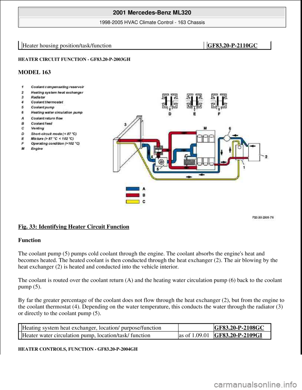
HEATER CIRCUIT FUNCTION - GF83.20-P-2003GH
MODEL 163
Fig. 33: Identifying Heater Circuit Function
Function
The coolant pump (5) pumps cold coolant through the engine. The coolant absorbs the engine's heat and
becomes heated. The heated coolant is then conducted through the heat exchanger (2). The air blowing by the
heat exchanger (2) is heated and conducted into the vehicle interior.
The coolant is routed over the coolant return (A) and the heating water circulation pump (6) back to the coolant
pump (5).
By far the greater percentage of the coolant does not flow through the heat exchanger (2), but from the engine to
the coolant thermostat (4). Depending on the water temperature, this conducts the water through the radiator (3)
or directly to the coolant pump (5).
HEATER CONTROLS, FUNCTION - GF83.20-P-2004GH
Heater housing position/task/function GF83.20-P-2110GC
Heating system heat exchanger, location/ purpose/function GF83.20-P-2108GC
Heater water circulation pump, location/task/ functionas of 1.09.01GF83.20-P-2109GI
2001 Mercedes-Benz ML320
1998-2005 HVAC Climate Control - 163 Chassis
me
Saturday, October 02, 2010 3:23:15 PMPage 43 © 2006 Mitchell Repair Information Company, LLC.
Page 3326 of 4133
Refrigerant circuit
The refrigerant compressor serves to compresses the gaseous refrigerant which heats up during the process, is
then routed into the condenser and thus cooled down. After purification in the fluid reservoir the liquid
refrigerant is injected into the evaporator. The refrigerant is vaporized and cools down. The refrigerant
compressor intakes the refrigerant again which has turned gaseous through the heat absorption process.
TABLE OF CONTENTS, AUTOMATIC AIR CONDITIONING (AAC) FUNCTION DESCRIPTION - GF83.40-P-0999GI
MODEL 163 as of 1.9.01 with CODE (580a) Automatic air conditioning
Ventilation, function GF83.10-P-2000GI
Heater circuit function GF83.20-P-2003GH
Automatic air conditioning push-button control module, function GF83.40-P-2000GI
Rear ventilation control panel, function GF83.40-P-2007GI
Refrigerant circuit function GF83.40-P-2001GI
Temperature control, function GF83.57-P-2000GI
Heater booster (ZUH), function GF83.70-P-0005GH
Residual engine heat utilization system, function GF83.75-P-2000GI
Automatic air conditioning (AAC), function GF83.40-P-
0001GI
Ventilation system function GF83.10-P-
2000GI
Heater circuit function GF83.20-P-
2003GH
Automatic air conditioning push-button control module, function GF83.40-P-
2000GI
Rear ventilation control panel, function GF83.40-P-
2007GI
Refrigerant circuit function GF83.40-P-
2001GI
Temperature control, function GF83.57-P-
2000GI
Heater booster (ZUH), function Engine
612.963GF83.70-P-
0005GH
Start heater operation, function Engine
612.963GF83.70-P-
2000GH
End heater operation, function Engine
612.963GF83.70-P-
2002GH
Regulate heater operation, function Engine
612.963GF83.70-P-
2004GH
Cancel heater operation, function Engine GF83.70-P-
2001 Mercedes-Benz ML320
1998-2005 HVAC Climate Control - 163 Chassis
me
Saturday, October 02, 2010 3:23:16 PMPage 82 © 2006 Mitchell Repair Information Company, LLC.
Page 3329 of 4133
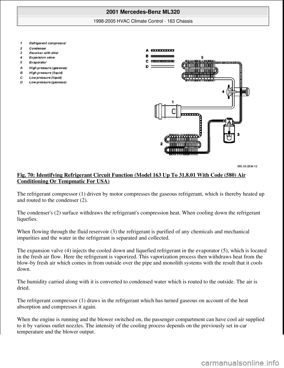
Fig. 70: Identifying Refrigerant Circuit Function (Model 163 Up To 31.8.01 With Code (580) Air
Conditioning Or Tempmatic For USA)
The refrigerant compressor (1) driven by motor compresses the gaseous refrigerant, which is thereby heated up
and routed to the condenser (2).
The condenser's (2) surface withdraws the refrigerant's compression heat. When cooling down the refrigerant
liquefies.
When flowing through the fluid reservoir (3) the refrigerant is purified of any chemicals and mechanical
impurities and the water in the refrigerant is separated and collected.
The expansion valve (4) injects the cooled down and liquefied refrigerant in the evaporator (5), which is located
in the fresh air flow. Here the refrigerant is vaporized. This vaporization process then withdraws heat from the
blow-by fresh air which comes in from outside over the pipe and monolith systems with the result that it cools
down.
The humidity carried along with it is converted to condensed water which is routed to the outside. The air is
dried.
The refrigerant compressor (1) draws in the refrigerant which has turned gaseous on account of the heat
absorption and compresses it again.
When the engine is running and the blower switched on, the passenger compartment can have cool air supplied
to it by various outlet nozzles. The intensity of the cooling process depends on the previously set in-car
temperature and the blower output.
2001 Mercedes-Benz ML320
1998-2005 HVAC Climate Control - 163 Chassis
me
Saturday, October 02, 2010 3:23:16 PMPage 85 © 2006 Mitchell Repair Information Company, LLC.
Page 3331 of 4133
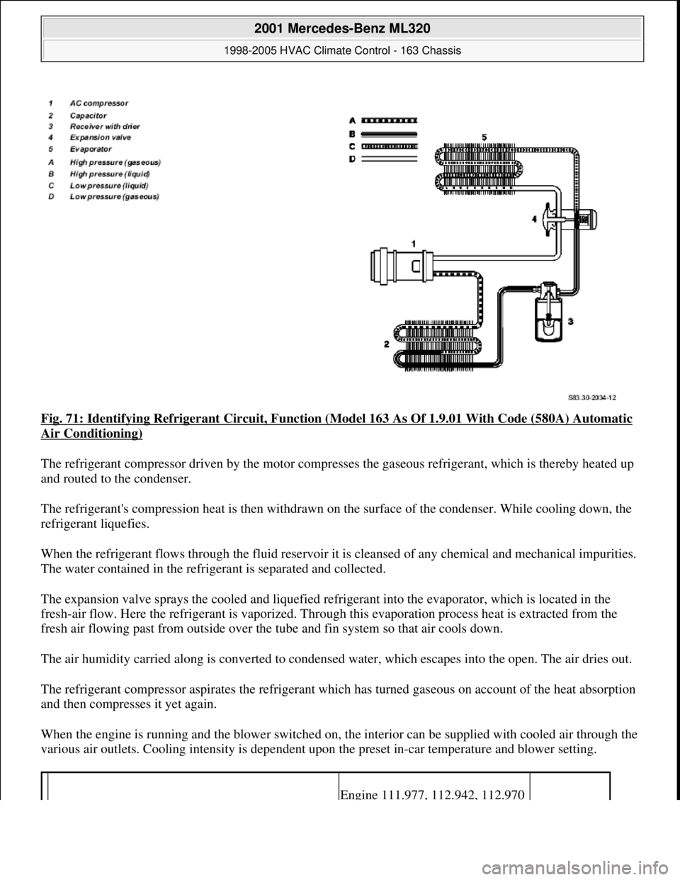
Fig. 71: Identifying Refrigerant Circuit, Function (Model 163 As Of 1.9.01 With Code (580A) Automatic
Air Conditioning)
The refrigerant compressor driven by the motor compresses the gaseous refrigerant, which is thereby heated up
and routed to the condenser.
The refrigerant's compression heat is then withdrawn on the surface of the condenser. While cooling down, the
refrigerant liquefies.
When the refrigerant flows through the fluid reservoir it is cleansed of any chemical and mechanical impurities.
The water contained in the refrigerant is separated and collected.
The expansion valve sprays the cooled and liquefied refrigerant into the evaporator, which is located in the
fresh-air flow. Here the refrigerant is vaporized. Through this evaporation process heat is extracted from the
fresh air flowing past from outside over the tube and fin system so that air cools down.
The air humidity carried along is converted to condensed water, which escapes into the open. The air dries out.
The refrigerant compressor aspirates the refrigerant which has turned gaseous on account of the heat absorption
and then compresses it yet again.
When the engine is running and the blower switched on, the interior can be supplied with cooled air through the
various air outlets. Cooling intensity is dependent upon the preset in-car temperature and blower setting.
Engine 111.977, 112.942, 112.970
2001 Mercedes-Benz ML320
1998-2005 HVAC Climate Control - 163 Chassis
me
Saturday, October 02, 2010 3:23:16 PMPage 87 © 2006 Mitchell Repair Information Company, LLC.
Page 3344 of 4133
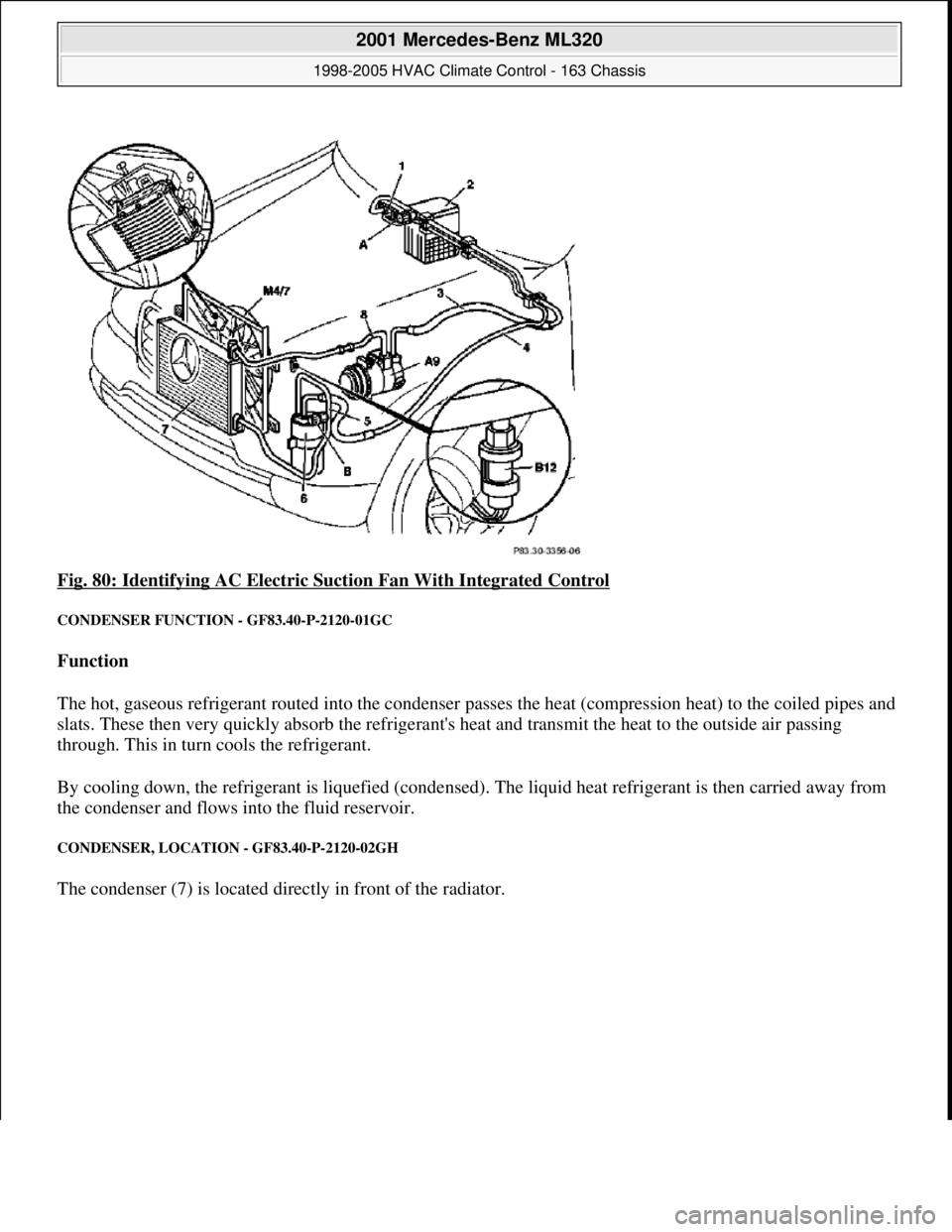
Fig. 80: Identifying AC Electric Suction Fan With Integrated Control
CONDENSER FUNCTION - GF83.40-P-2120-01GC
Function
The hot, gaseous refrigerant routed into the condenser passes the heat (compression heat) to the coiled pipes and
slats. These then very quickly absorb the refrigerant's heat and transmit the heat to the outside air passing
through. This in turn cools the refrigerant.
By cooling down, the refrigerant is liquefied (condensed). The liquid heat refrigerant is then carried away from
the condenser and flows into the fluid reservoir.
CONDENSER, LOCATION - GF83.40-P-2120-02GH
The condenser (7) is located directly in front of the radiator.
2001 Mercedes-Benz ML320
1998-2005 HVAC Climate Control - 163 Chassis
me
Saturday, October 02, 2010 3:23:16 PMPage 100 © 2006 Mitchell Repair Information Company, LLC.
Page 3377 of 4133
ENGINE 111, 112, 271, 272, 611, 612, 646 in MODEL 203.7 with CODE (580) Air conditioning (or
Tempmatic for USA) with CODE (580) Automatic air conditioning with CODE (581) Automatic air
conditioning with CODE (581) Comfort automatic air conditioning
ENGINE 112.942 /970, 113.942 /965 /981, 612.963, 628.963 in MODEL 163 as of 1.9.01 with CODE (580)
Automatic air conditioning
ENGINE 112, 113, 271, 272, 273, 612, 642, 646 in MODEL 209.3
ENGINE 112, 113, 271, 272, 273, 642 in MODEL 209.4
Shown on model 203
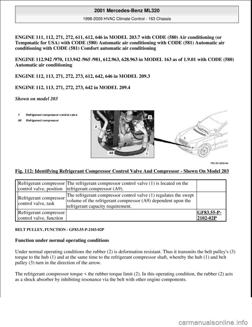
Fig. 112: Identifying Refrigerant Compressor Control Valve And Compressor
- Shown On Model 203
BELT PULLEY, FUNCTION - GF83.55-P-2103-02P
Function under normal operating conditions
Under normal operating conditions the rubber (2) is deformation resistant. Thus it transmits the belt pulley's (3)
torque to the hub (1) and at the same time to the refrigerant compressor shaft, whereby the hub (1) and belt
pulley (3) turn in the direction of the arrow.
The refrigerant compressor torque < the rubber torque limit (2). In this operating condition, the rubber (2) acts
as a shock absorber b
y inhibiting resonance via the belt with other engine components.
Refrigerant compressor
control valve, positionThe refrigerant compressor control valve (1) is located on the
refrigerant compressor (A9).
Refrigerant compressor
control valve, taskThe refrigerant compressor control valve (1) regulates the swept
volume of the refrigerant compressor (A9) dependent upon the
refrigerant capacity requirement.
Refrigerant compressor
control valve, function GF83.55-P-
2102-02P
2001 Mercedes-Benz ML320
1998-2005 HVAC Climate Control - 163 Chassis
me
Saturday, October 02, 2010 3:23:17 PMPage 133 © 2006 Mitchell Repair Information Company, LLC.
Page 3459 of 4133
Notes on handling refrigerant
R134aAll models fitted with air conditioning
AH83.30-
N-0003-
01A
1.1
Remove
additional
fan (M4)
Models 163.136 /154/157 /172 with air
conditioning or for USA Tempmatic, code
580.AR83.30-
P-5600GH
2.1Remove intercooler Only models 163.113/ 128.
Model 163.113AR09.41-P-
6817MM
Model 163.128AR09.41-P-
6817CD
3Discharge air conditioning system
Installation: Evacuate, refill air
conditioning system and check for proper
operation and tightness.AR83.30-
P-1760GH
4.1Detach lower engine compartment
panelingModel 163.172/174/175AR61.20-
P-1105GH
4.2Remove noise encapsulation Removal: Only remove front part.
Model 163.113/128AR94.30-P-
5400GH
5.1Remove air guide Only if present Located at front
crossmember, in center behind front bumper.
6Unscrew bolts at bottom of
electric fan or fan shroud. Also remove sheet metal nuts.
7Remove attachment parts (20) and
rubber shock absorber(21) Removal: Lower attaching parts and
damper rubber.
Installation: Replace attaching parts.
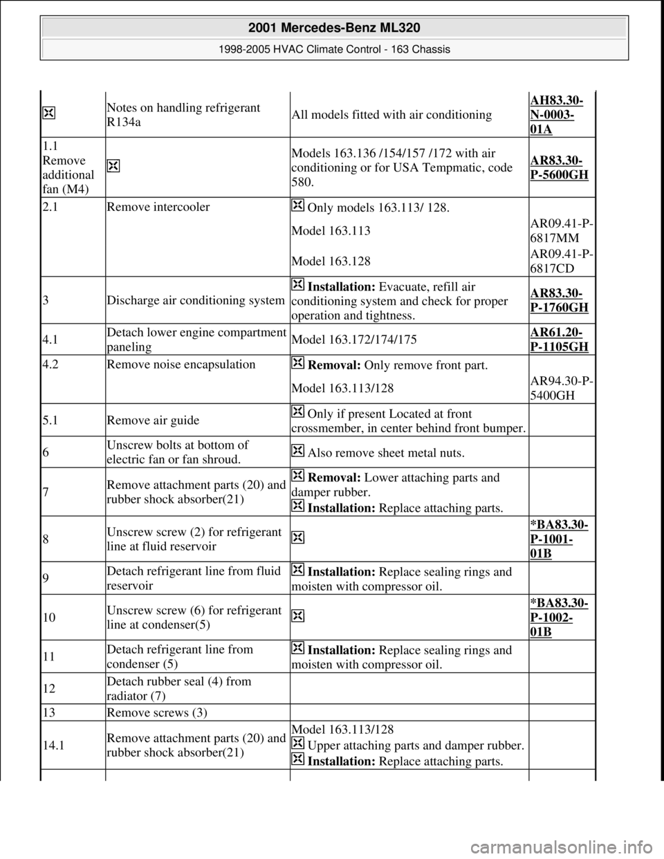
8Unscrew screw (2) for refrigerant
line at fluid reservoir
*BA83.30-
P-1001-
01B
9Detach refrigerant line from fluid
reservoir Installation: Replace sealing rings and
moisten with compressor oil.
10Unscrew screw (6) for refrigerant
line at condenser(5)
*BA83.30-
P-1002-
01B
11Detach refrigerant line from
condenser (5) Installation: Replace sealing rings and
moisten with compressor oil.
12Detach rubber seal (4) from
radiator (7)
13Remove screws (3)
14.1Remove attachment parts (20) and
rubber shock absorber(21)Model 163.113/128
Upper attaching parts and damper rubber.
Installation: Replace attaching parts.
2001 Mercedes-Benz ML320
1998-2005 HVAC Climate Control - 163 Chassis
me
Saturday, October 02, 2010 3:23:18 PMPage 215 © 2006 Mitchell Repair Information Company, LLC.
Page 3482 of 4133

GF54.30-P-3003A
Indicator/warning messages triggered via CAN data buses, function
24.10.96
MODEL
129, 140 as of 1.6.96,
163, 168, 170,
202 as of 1.8.96,
208 up to 31.7.99,
210 as of 1.6.96 up to 30.6.99
Indicator and warning displays triggered via CAN
Low brake fluid level/parking brake indicator lamp (A1e7)
The parking brake signal comes from the traction system
control module.
The brake fluid signal comes directly from the switch (S11)
(except model 163).
Brake pad wear indicator lamp (A1e6)
The parking brake signal comes from the traction system
control module (N47)
Low engine oil level indicator lamp (A1e12)
The oil level signal comes from the injection system control
module (N3).
For vehicles with ASSYST, also refer to document: ASSYST
engine oil monitoring.
Preglow indicator lamp (A1e16)
The signal comes directly from the injection system control
module (N3).
Coolant level and temperature warning lamp (A1e11) model 168
only as of 9.99
The coolant temperature signal comes from the injection
system control module (N3)
-----------------------------------------------------------------------------------------
ABS MIL (A1e17)
The parking brake signal comes from the traction system
control module (N47).
"CHECK ENGINE" MIL (A1e26),
I
only
The signal comes from the injection system control module (N3)
ETS (A1e35) or ASR (A1e22) or ESP (A1e42) MIL
Lamp illuminated if there is a fault in the respective system.
The signal comes from the traction system control module
(N47).
ETS (A1e36) or ASR (A1e21) or ESP (A1e41) warning lamp
The lamp indicates that the respective system is active.
The signal comes from the traction system control module
(N47).
-----------------------------------------------------------------------------------------
Severe leak warning (
I
as of 97 only)
The fuel reserve indicator lamp (A1e4) flashes. The signal
comes from the injection system control module (N3).
The warning takes place at the earliest 30 minutes after cold
start with the engine idling and the vehicle stationary.
Also refer to document: Purge system with leak test, function
Fog lamps indicator lamp (A1e57), model 163 only except
I
)
The signal comes from the All-activity module (AAM, N10)
"LOW RANGE" indicator lamp (A1e53), model 163 only
The signal comes from the transfer case control module (N78)
Active service system (ASSYST)
Engines 112, 113, 611 (engines with oil
sensor)
GF00.20-P-2009A
Engine oil monitoring, function
Model 210 as of 01.03.97 with engine M111,
OM602, OM604, OM605 and OM606
As of 06.97 models 129, 140, 170, 202 except
engines 112, 113, 611
(Valid for engines with low oil level switch).
GF00.20-P-2009B
Displaying coolant temperature, function
Model 168 as of 9.99
GF54.30-P-3020GC
Purge system with leak test, function
GF47.30-P-3016L
Bus systems, overall function
GF54.00-P-0004A
Copyright DaimlerChrysler AG 04.06.2006 CD-Ausgabe G/10/04 . This WIS print-out will not be recorde
d by Modification services.
Page 1