Page 2611 of 4133
Fuel tank
Number
Designation
Models
163.113/
128/ 136/
154/157/
172/175
Model
163.174
BA47.10-P-1001-01D
Screws for tensioning straps
Nm
2020
BA47.10-P-1002-01D
Longitudinal strut for check straps
Nm
2020
Rear axle shock absorber
Number
Designation
Model
Series 163
BA32.25-P-1001-03D
Self-locking nut, shock absorber to lower
wishbone
Nm
85
Fuel tank
Number
Designation
Models
163.113/
136/154/
172 up to
31.08.01
Models
163.113/
136/154/
172 as of
01.09.01
Models
163.157/
175
BF47.10-P-1001-01A
Fuel tank capacity
Total capacity
Liter
7283
Reserve capacity
Liter
1012
Pliers
163 589 00 37 00
Copyright DaimlerChrysler AG 28.05.2006 CD-Ausgabe G/10/04 . This WIS print-out will not be recorde
d by Modification services.
Page 4
Page 2672 of 4133

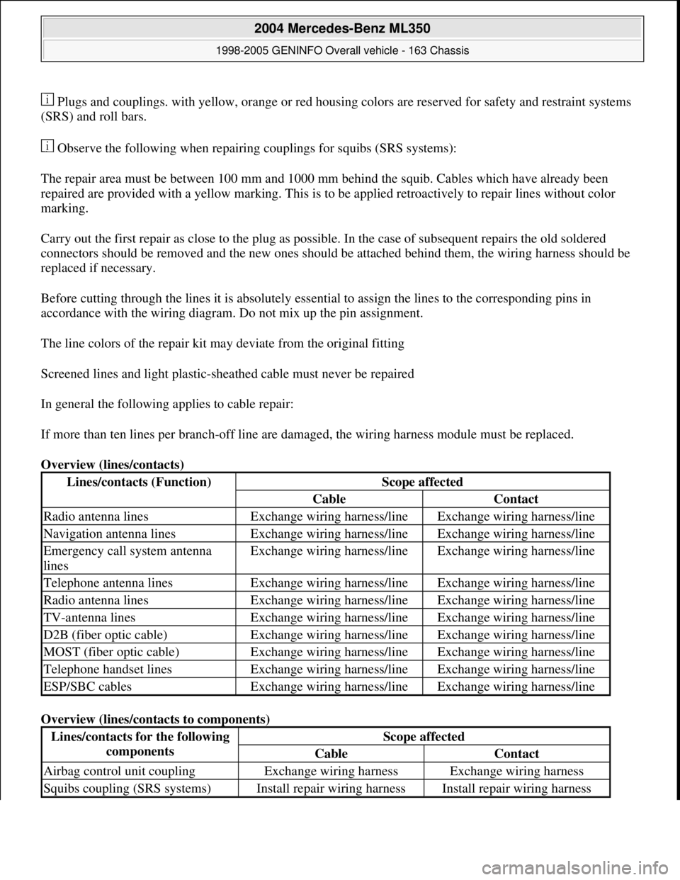
Plugs and couplings. with yellow, orange or red housing colors are reserved for safety and restraint systems
(SRS) and roll bars.
Observe the following when repairing couplings for squibs (SRS systems):
The repair area must be between 100 mm and 1000 mm behind the squib. Cables which have already been
repaired are provided with a yellow marking. This is to be applied retroactively to repair lines without color
marking.
Carry out the first repair as close to the plug as possible. In the case of subsequent repairs the old soldered
connectors should be removed and the new ones should be attached behind them, the wiring harness should be
replaced if necessary.
Before cutting through the lines it is absolutely essential to assign the lines to the corresponding pins in
accordance with the wiring diagram. Do not mix up the pin assignment.
The line colors of the repair kit may deviate from the original fitting
Screened lines and light plastic-sheathed cable must never be repaired
In general the following applies to cable repair:
If more than ten lines per branch-off line are damaged, the wiring harness module must be replaced.
Overview (lines/contacts)
Overview (lines/contacts to components)
Lines/contacts (Function)Scope affected
CableContact
Radio antenna linesExchange wiring harness/lineExchange wiring harness/line
Navigation antenna linesExchange wiring harness/lineExchange wiring harness/line
Emergency call system antenna
linesExchange wiring harness/lineExchange wiring harness/line
Telephone antenna linesExchange wiring harness/lineExchange wiring harness/line
Radio antenna linesExchange wiring harness/lineExchange wiring harness/line
TV-antenna linesExchange wiring harness/lineExchange wiring harness/line
D2B (fiber optic cable)Exchange wiring harness/lineExchange wiring harness/line
MOST (fiber optic cable)Exchange wiring harness/lineExchange wiring harness/line
Telephone handset linesExchange wiring harness/lineExchange wiring harness/line
ESP/SBC cablesExchange wiring harness/lineExchange wiring harness/line
Lines/contacts for the following
componentsScope affected
CableContact
Airbag control unit couplingExchange wiring harnessExchange wiring harness
Squibs coupling (SRS systems)Install repair wiring harnessInstall repair wiring harness
2004 Mercedes-Benz ML350
1998-2005 GENINFO Overall vehicle - 163 Chassis
me
Saturday, October 02, 2010 3:47:44 PMPage 27 © 2006 Mitchell Repair Information Company, LLC.
Page 2864 of 4133

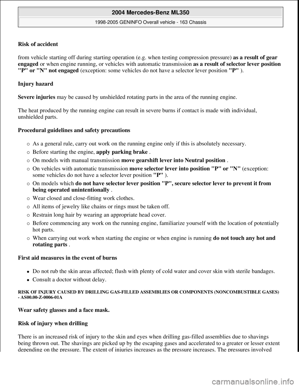
Risk of accident
from vehicle starting off during starting operation (e.g. when testing compression pressure) as a result of gear
engaged or when engine running, or vehicles with automatic transmission as a result of selector lever position
"P" or "N" not engaged (exception: some vehicles do not have a selector lever position "P" ).
Injury hazard
Severe injuries may be caused by unshielded rotating parts in the area of the running engine.
The heat produced by the running engine can result in severe burns if contact is made with individual,
unshielded parts.
Procedural guidelines and safety precautions
As a general rule, carry out work on the running engine only if this is absolutely necessary.
Before starting the engine, apply parking brake .
On models with manual transmission move gearshift lever into Neutral position .
On vehicles with automatic transmission move selector lever into position "P" or "N" (exception:
some vehicles do not have a selector lever position "P" ).
On models which do not have selector lever position "P", secure selector lever to prevent it from
being operated unintentionally .
Wear closed and close-fitting work clothes.
All items of jewelry like chains or rings must be taken off.
Restrain long hair by wearing an appropriate head cover.
Before commencing any work on the running engine, familiarize yourself with the location of potentially
hot parts.
When carrying out work when starting the engine or when engine is running do not touch any hot and
rotating parts .
First aid measures in the event of burns
Do not rub the skin areas affected; flush with plenty of cold water and cover skin with sterile bandages.
Consult a doctor without delay.
RISK OF INJURY CAUSED BY DRILLING GAS-FILLED ASSEMBLIES OR COMPONENTS (NONCOMBUSTIBLE GASES)
- AS00.00-Z-0006-01A
Wear safety glasses and a face mask.
Risk of injury when drilling
There is an increased risk of injury to the skin and eyes when drilling gas-filled assemblies due to shavings
being thrown out. The shavings are picked up by the escaping gases and accelerated to a greater or lesser extent
depending on the pressure. The extent of injuries increases as the pressure increases. The pressures involved
2004 Mercedes-Benz ML350
1998-2005 GENINFO Overall vehicle - 163 Chassis
me
Saturday, October 02, 2010 3:47:47 PMPage 219 © 2006 Mitchell Repair Information Company, LLC.
Page 2883 of 4133
![MERCEDES-BENZ ML500 1997 Complete Repair Manual MODELS 124, 129, 140, 163 up to 30.11.99, 163 as of 1.9.01, 168, 170, 201, 202, 208, 210, 215, 220
EXPLANATION OF SYMBOLS FOR TESTERS AND COMPONENTS - AD00.00-P-2000-01A
0.0 [] 1Key to diagnostics
s MERCEDES-BENZ ML500 1997 Complete Repair Manual MODELS 124, 129, 140, 163 up to 30.11.99, 163 as of 1.9.01, 168, 170, 201, 202, 208, 210, 215, 220
EXPLANATION OF SYMBOLS FOR TESTERS AND COMPONENTS - AD00.00-P-2000-01A
0.0 [] 1Key to diagnostics
s](/manual-img/4/57308/w960_57308-2882.png)
MODELS 124, 129, 140, 163 up to 30.11.99, 163 as of 1.9.01, 168, 170, 201, 202, 208, 210, 215, 220
EXPLANATION OF SYMBOLS FOR TESTERS AND COMPONENTS - AD00.00-P-2000-01A
0.0 [] 1Key to diagnostics
symbols AD00.00-P-2001A
0.0 [] 2Diagnosis assignmentexcept models 215, 220AD00.00-P-2002A
0.0 [] 3Connect test equipment
diagnosisexcept model 215AD00.00-P-2003A
0.0 [] 4Diagnostic procedureonly for vehicle systems
that can be diagnosed using
STAR DIAGNOSISAD00.00-P-2004A
DescriptionLogoDescriptionLogoDescriptionLogo
ABS Adapter Battery Short-circuit
35-pin socket
box Direct current
generator Short-circuit to
ground
126-pin socket
box Direct current
motor Open-circuit
Function
generator Capacitor Multimeter
alternating
voltage type of
measurement
Hand-Held
Tester Coil Multimeter
resistance type of
measurement
Pulse counter Resistance Function
generator square-
wave signal shape
Lambda control
tester Ground Function
generator
sinusoidal signal
shape
Pressure gauge In order Oscilloscope
Multimeter Fault Adapter cable
with light-
emitting diode
Decade resistor Greater than > Multimeter direct
current type of
measurement
Bridge Less than < Multimeter
alternating
current type of
measurement
2004 Mercedes-Benz ML350
1998-2005 GENINFO Overall vehicle - 163 Chassis
me
Saturday, October 02, 2010 3:47:48 PMPage 238 © 2006 Mitchell Repair Information Company, LLC.
Page 2930 of 4133
Fig. 415: Identifying Wiring Harness Repair Kit, Basic (000 589 13 99 00)
Fig. 416: Identifying Wiring Ha rness Repair Kit (220 589 02 99 00)
Fig. 417: Identifying Blad e Holder With Clamping Pliers (220 589 02 99 50)
Fig. 418: Identifying SLK 2.8 Blade (220 589 02 99 62)
Secondary unlocking for versio n with contact retainer (SLK)
1. Using a suitable tool, push tabs of contact retainer (1) in direction of arrow out of locked position.
Shown on 2-pin SLK connector
2004 Mercedes-Benz ML350
1998-2005 GENINFO Overall vehicle - 163 Chassis
me
Saturday, October 02, 2010 3:47:49 PMPage 285 © 2006 Mitchell Repair Information Company, LLC.
Page 2931 of 4133
Fig. 419: Pushing Tabs Of Contact Retainer - Shown On 2-Pin SLK Connector
Unpin contact pins form connector (SLK)
1. Insert blade holder with clamping pliers and SLK 2.8 blade from front side through openings at
contact cavity of connector (1).
Insert tool carefully to prevent damaging webs at openings of contact cavity.
This presses together the springs of the contact pin (2).
2. A slight tug on the corresponding cable will remove the contact pin from the connector.
Fig. 420: Contact Pins From Connector (SLK)
2004 Mercedes-Benz ML350
1998-2005 GENINFO Overall vehicle - 163 Chassis
me
Saturday, October 02, 2010 3:47:49 PMPage 286 © 2006 Mitchell Repair Information Company, LLC.
Page 2935 of 4133
Fig. 431: Identifying SLK 2.8 Blade (220 589 01 99 62)
Secondary release for version with locking bar (SLK)
1. Using a suitable tool, push tabs of locking bar(1) in direction of arrow out of locked position.
Shown on a 6-pin SLK coupling
2004 Mercedes-Benz ML350
1998-2005 GENINFO Overall vehicle - 163 Chassis
me
Saturday, October 02, 2010 3:47:49 PMPage 290 © 2006 Mitchell Repair Information Company, LLC.
Page 2936 of 4133
Fig. 432: Pushing Tabs Of Locking Bar - Shown On A 6-Pin SLK Coupling
Secondary release for version with locking slider (SLK)
1. Using a suitable tool, move locking slider (3) in direction shown by arrow.
Shown on a 58-pin SLK coupling
2004 Mercedes-Benz ML350
1998-2005 GENINFO Overall vehicle - 163 Chassis
me
Saturday, October 02, 2010 3:47:49 PMPage 291 © 2006 Mitchell Repair Information Company, LLC.