Page 1519 of 4133
Fog and other lighting influences, e.g., due to oncoming traffic, do not have any effect on the automatic
driving light actuation.
Automatic driving light actuation when starting a journey and during it
Automatic driving light actuation with driving lights is only possible when the engine is running (circuit
61 ON).
When the engine is switched off and the electronic starter switch is in position "2" (circuit 15 ON) only
the side lamps and the license plate lamps are actuated.
Driving light actuation is disabled as soon as one of the basic prerequisites changes, e.g. when changing
from darkness to daylight after driving through a tunnel.
Automatic driving light actuation at the end of a journey or in darkness
After switching off the engine (circuit 61 OFF) and when the electronic starter switch is in position
"2" (circuit 15 ON), only the side lamps and the license plate lamps remain on.
The exterior lighting is switched off as of key position "1" (circuit 15R).
DAYTIME RUNNING LIGHT ACTUATION, FUNCTION - GF82.10-P-3005GH
MODEL 163 as of 01.09.01
With daytime running lamps the low beam, the side lamps and the license plate lamps are switched on if the
engine is running (there are national variants).
Function prerequisites:
Circuit 61 "ON"
In "AUTO" position of the exterior lamp switch daytime running lamps and automatic driving lights are
OR gated, i.e. depending on the prerequisites daytime running lamps or automatic driving lights are switched
on.
For the daytime running lamp conditions, there is no difference between the positions "0" and "AUTO" of
the exterior lamp switch.
Corresponding to the national legislation, the daytime running lamps can be coded in different variants via
Star Diagnosis.
Canada and USA
Table of contents,
function description for
exterior lighting GF82.10-P-0999A
2001 Mercedes-Benz ML320
1998-2005 ACCESSORIES & BODY, CAB Electrical System - Body - 163 Chassis
me
Saturday, October 02, 2010 3:30:04 PMPage 24 © 2006 Mitchell Repair Information Company, LLC.
Page 1674 of 4133
COMAND OPERATING AND DISPLAY SYSTEM SCREEN REMAINS DARK AFTER STARTING ENGINE - AF82.85-P-
2001A
MODEL 163, 203, 208, 210, 215, 220, 230, 463 with CODE (352) COMAND operating and display system
NAVIGATION SYSTEM DISPLAYS INCORRECT ADDRESS - AF82.85-P-2100A
MODEL 163.154 /174 #A as of 289565, 163.157/175 with CODE (357) Navigation system - additional unit
with CODE (494a) USA version
Mainland USA only,
DVD version 2002-2 only
Operation no. of the operation texts or standard texts and flat rates
203 820 07 51Clip for portable CTEL mountAs required
203 820 52 15Interference suppression converterAs required
Damage codeCauseRemedy
Current vehicle voltage. Do not remove/install
COMAND.
1. Point out to customer
that in the event of
problems the fault can
be eliminated by
switching off/on
(ON/OFF button) the
COMAND.
RangeOp. no.Operation textFlat rateAcc. no.Code
P023917Flash Navigation
system0.3 h82 853 90-
Damage codeCauseRemedy
Database mismatch.1 Start engine.
2 Turn on MCS unit.
3 Press NAVI MENU
button.
4 Ensure MAP REGION
is set to MAINLAND US
under SYSTEM SETUP
menu.
5 Eject customer
Navigation DVD.
2001 Mercedes-Benz ML320
1998-2005 ACCESSORIES & BODY, CAB Electrical System - Body - 163 Chassis
me
Saturday, October 02, 2010 3:30:07 PMPage 179 © 2006 Mitchell Repair Information Company, LLC.
Page 1819 of 4133
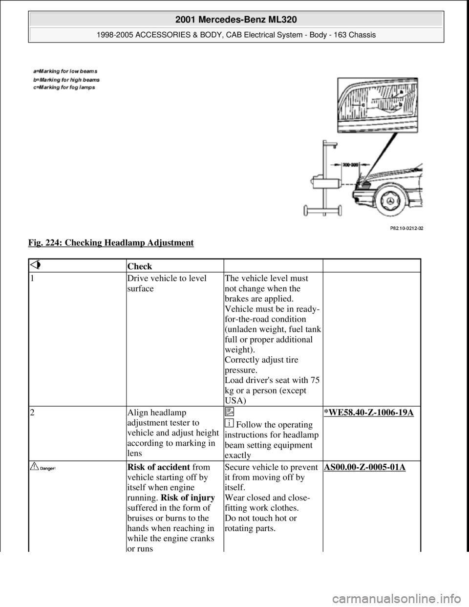
Fig. 224: Checking Headlamp Adjustment
Check
1Drive vehicle to level
surfaceThe vehicle level must
not change when the
brakes are applied.
Vehicle must be in ready-
for-the-road condition
(unladen weight, fuel tank
full or proper additional
weight).
Correctly adjust tire
pressure.
Load driver's seat with 75
kg or a person (except
USA)
2Align headlamp
adjustment tester to
vehicle and adjust height
according to marking in
lens
Follow the operating
instructions for headlamp
beam setting equipment
exactly*WE58.40-Z-1006-19A
Risk of accident from
vehicle starting off by
itself when engine
running. Risk of injury
suffered in the form of
bruises or burns to the
hands when reaching in
while the engine cranks
or runsSecure vehicle to prevent
it from moving off by
itself.
Wear closed and close-
fitting work clothes.
Do not touch hot or
rotating parts.AS00.00-Z-0005-01A
2001 Mercedes-Benz ML320
1998-2005 ACCESSORIES & BODY, CAB Electrical System - Body - 163 Chassis
me
Saturday, October 02, 2010 3:30:10 PMPage 324 © 2006 Mitchell Repair Information Company, LLC.
Page 1848 of 4133
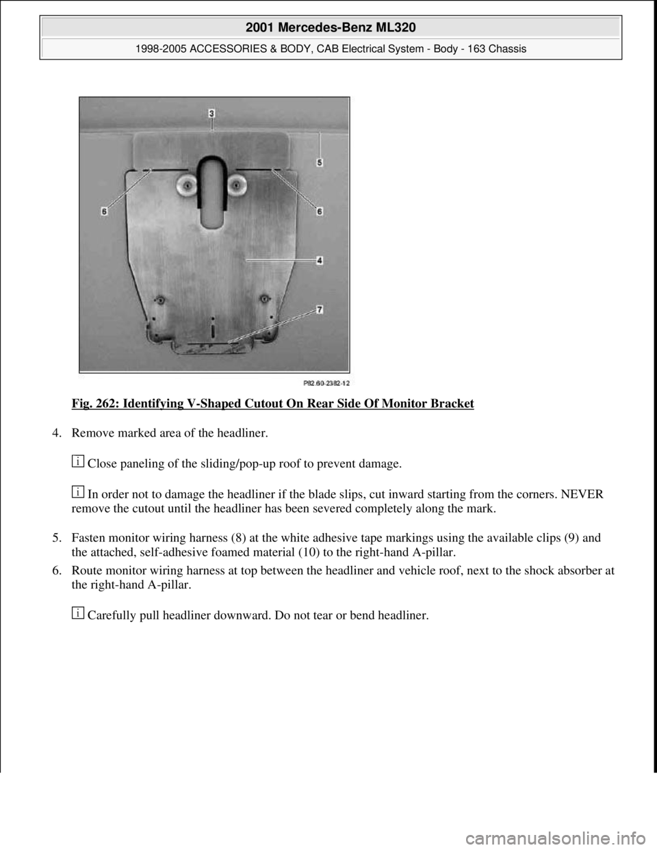
Fig. 262: Identifying V-Shaped Cutout On Rear Side Of Monitor Bracket
4. Remove marked area of the headliner.
Close paneling of the sliding/pop-up roof to prevent damage.
In order not to damage the headliner if the blade slips, cut inward starting from the corners. NEVER
remove the cutout until the headliner has been severed completely along the mark.
5. Fasten monitor wiring harness (8) at the white adhesive tape markings using the available clips (9) and
the attached, self-adhesive foamed material (10) to the right-hand A-pillar.
6. Route monitor wiring harness at top between the headliner and vehicle roof, next to the shock absorber at
the right-hand A-pillar.
Carefull
y pull headliner downward. Do not tear or bend headliner.
2001 Mercedes-Benz ML320
1998-2005 ACCESSORIES & BODY, CAB Electrical System - Body - 163 Chassis
me
Saturday, October 02, 2010 3:30:11 PMPage 353 © 2006 Mitchell Repair Information Company, LLC.
Page 1854 of 4133
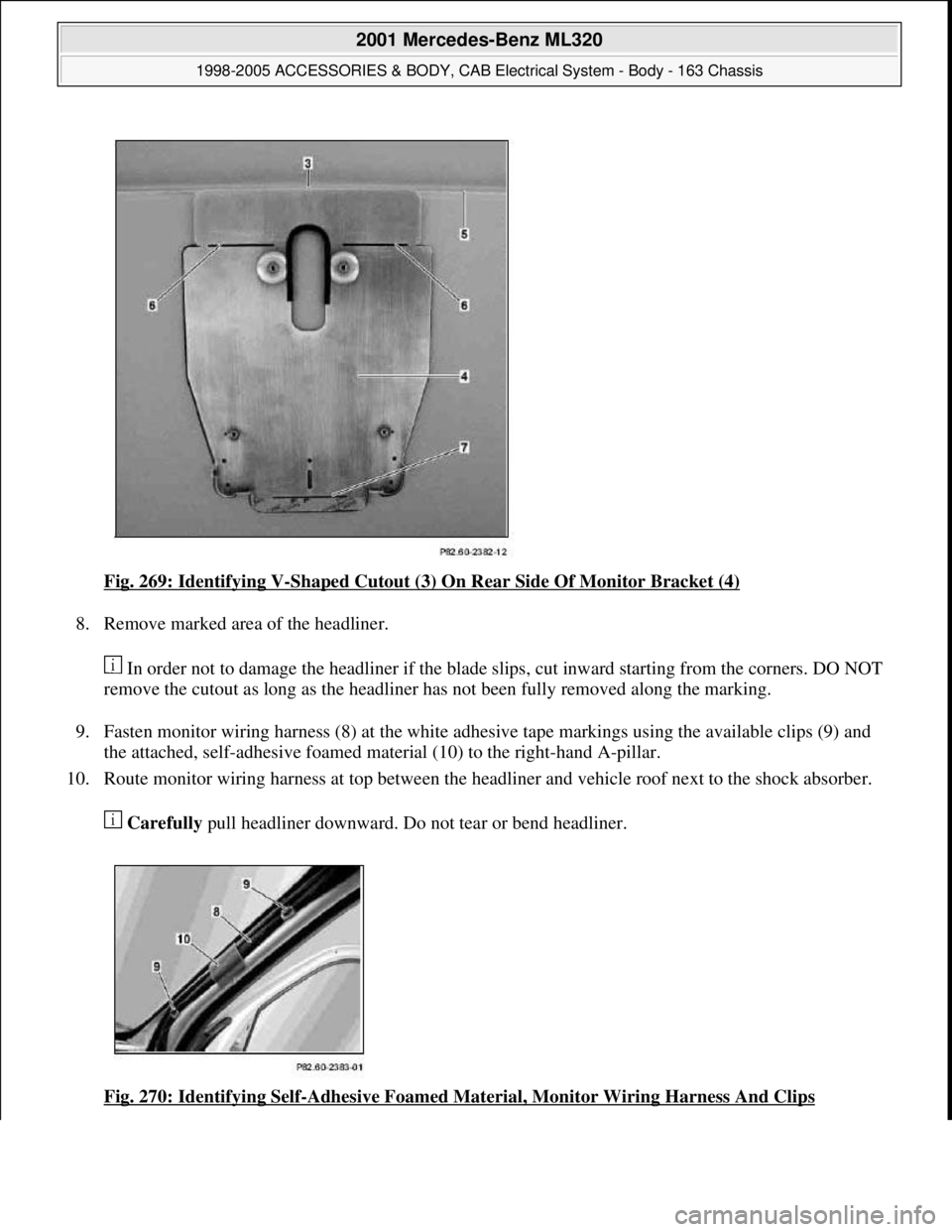
Fig. 269: Identifying V-Shaped Cutout (3) On Rear Side Of Monitor Bracket (4)
8. Remove marked area of the headliner.
In order not to damage the headliner if the blade slips, cut inward starting from the corners. DO NOT
remove the cutout as long as the headliner has not been fully removed along the marking.
9. Fasten monitor wiring harness (8) at the white adhesive tape markings using the available clips (9) and
the attached, self-adhesive foamed material (10) to the right-hand A-pillar.
10. Route monitor wiring harness at top between the headliner and vehicle roof next to the shock absorber.
Carefully pull headliner downward. Do not tear or bend headliner.
Fig. 270: Identifying Self
-Adhesive Foamed Material, Monitor Wiring Harness And Clips
2001 Mercedes-Benz ML320
1998-2005 ACCESSORIES & BODY, CAB Electrical System - Body - 163 Chassis
me
Saturday, October 02, 2010 3:30:11 PMPage 359 © 2006 Mitchell Repair Information Company, LLC.
Page 1860 of 4133
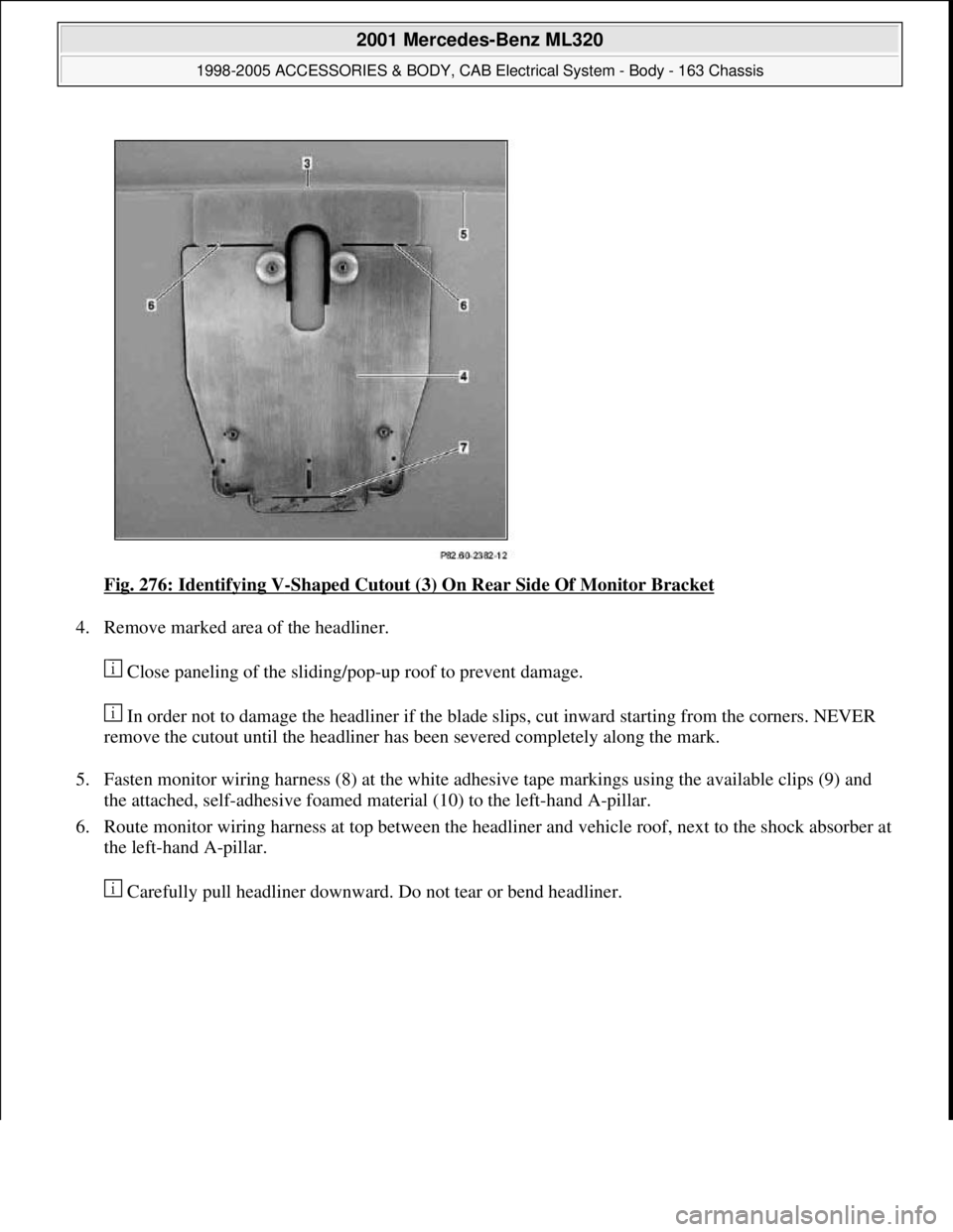
Fig. 276: Identifying V-Shaped Cutout (3) On Rear Side Of Monitor Bracket
4. Remove marked area of the headliner.
Close paneling of the sliding/pop-up roof to prevent damage.
In order not to damage the headliner if the blade slips, cut inward starting from the corners. NEVER
remove the cutout until the headliner has been severed completely along the mark.
5. Fasten monitor wiring harness (8) at the white adhesive tape markings using the available clips (9) and
the attached, self-adhesive foamed material (10) to the left-hand A-pillar.
6. Route monitor wiring harness at top between the headliner and vehicle roof, next to the shock absorber at
the left-hand A-pillar.
Carefull
y pull headliner downward. Do not tear or bend headliner.
2001 Mercedes-Benz ML320
1998-2005 ACCESSORIES & BODY, CAB Electrical System - Body - 163 Chassis
me
Saturday, October 02, 2010 3:30:11 PMPage 365 © 2006 Mitchell Repair Information Company, LLC.
Page 1866 of 4133
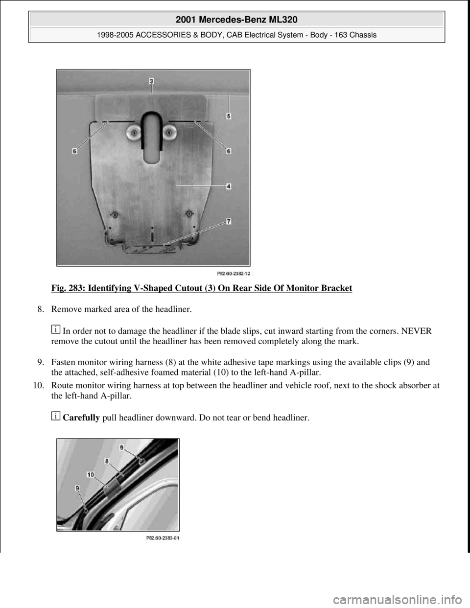
Fig. 283: Identifying V-Shaped Cutout (3) On Rear Side Of Monitor Bracket
8. Remove marked area of the headliner.
In order not to damage the headliner if the blade slips, cut inward starting from the corners. NEVER
remove the cutout until the headliner has been removed completely along the mark.
9. Fasten monitor wiring harness (8) at the white adhesive tape markings using the available clips (9) and
the attached, self-adhesive foamed material (10) to the left-hand A-pillar.
10. Route monitor wiring harness at top between the headliner and vehicle roof, next to the shock absorber at
the left-hand A-pillar.
Carefully pull headliner downward. Do not tear or bend headliner.
2001 Mercedes-Benz ML320
1998-2005 ACCESSORIES & BODY, CAB Electrical System - Body - 163 Chassis
me
Saturday, October 02, 2010 3:30:12 PMPage 371 © 2006 Mitchell Repair Information Company, LLC.
Page 1875 of 4133
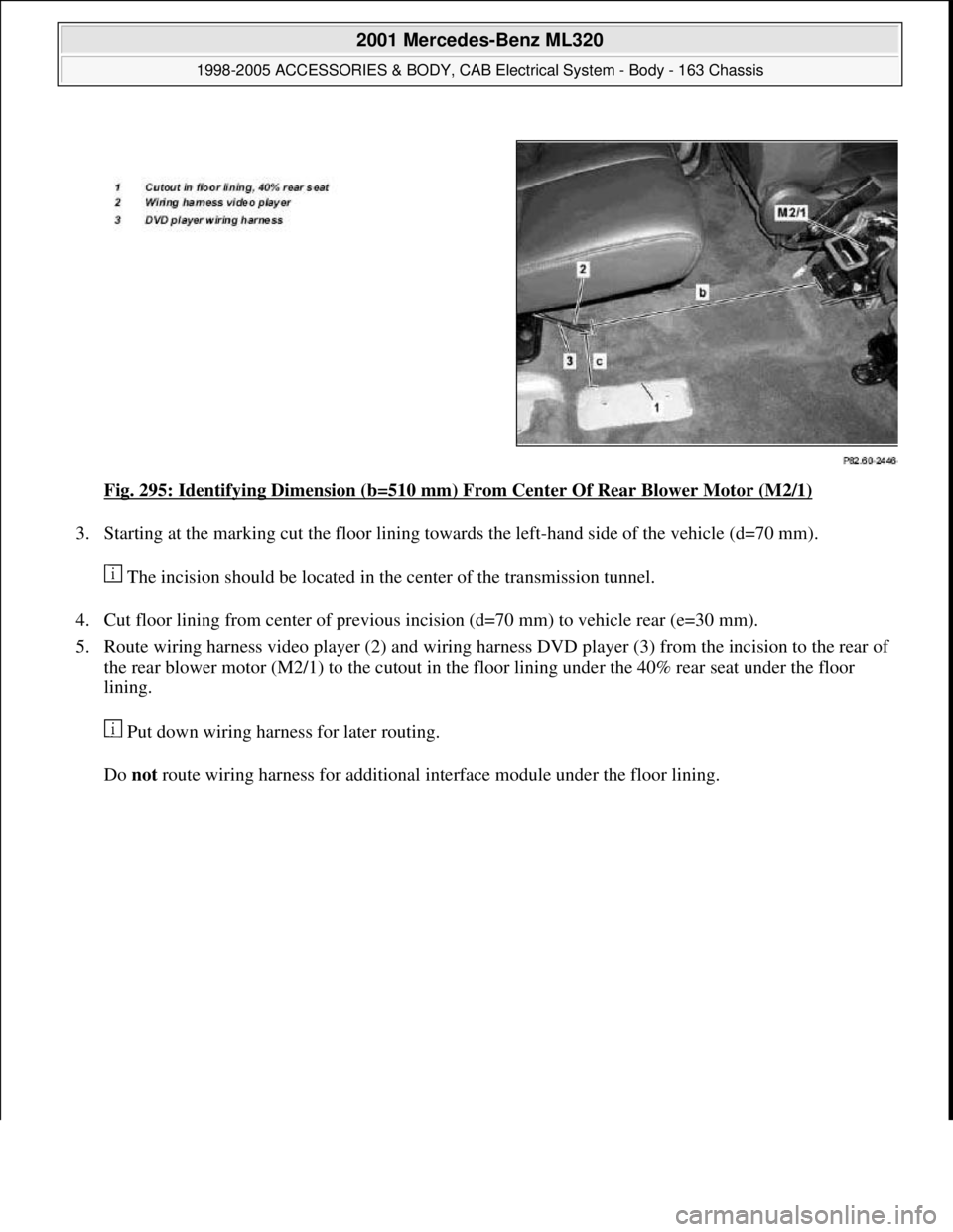
Fig. 295: Identifying Dimension (b=510 mm) From Center Of Rear Blower Motor (M2/1)
3. Starting at the marking cut the floor lining towards the left-hand side of the vehicle (d=70 mm).
The incision should be located in the center of the transmission tunnel.
4. Cut floor lining from center of previous incision (d=70 mm) to vehicle rear (e=30 mm).
5. Route wiring harness video player (2) and wiring harness DVD player (3) from the incision to the rear of
the rear blower motor (M2/1) to the cutout in the floor lining under the 40% rear seat under the floor
lining.
Put down wiring harness for later routing.
Do not route wirin
g harness for additional interface module under the floor lining.
2001 Mercedes-Benz ML320
1998-2005 ACCESSORIES & BODY, CAB Electrical System - Body - 163 Chassis
me
Saturday, October 02, 2010 3:30:12 PMPage 380 © 2006 Mitchell Repair Information Company, LLC.