Page 2321 of 4133
position sensor (11)
11Remove camshaft
sprockets (10) Lock right and left
camshaft with locating
plates.
Locating plateFig. 11
Locating plateFig. 12
Open-end wrenchFig. 22
Insertion toolFig. 66
Torque wrench001589722100
*BA05.20-P-1001-01B
After installation: ?
Inspect timing of engine.AR05.10-P-6858V
? If necessary after
checking:
Set basic position of
camshafts.AR05.20-P-6020AU
12Remove camsha ft bearing
bridges (9)Engines 112, 113 except
code (479) Cylinder
shutoff.AR05.20-P-7103AU
Engine 113 with code
(479) cylinder shutoff.AR05.20-P-7103AV
13Position piston of cylinder
to be processed to TDC Crank engine at
crankshaft for this
purpose and hold up
timing chain (so that it
does not jam).
Installation: Before
installing the camshaft
sprockets, again turn
back the crankshaft in the
starting position to 40 °
as per ignition TDC at
the first cylinder.
14Install retaining lock (13)
for crankshaft After setting TDC of
cylinder to be processed,
in order to prevent
crankshaft turning
further.AR03.30-P-5000B
15Connect up cylinder leak
tester (12) Turn connection
hose of cylinder leak
tester into the relevant
spark plug hole.*WH58.30-Z-1015-05A
16Pressurize compression
chamberWith a pressure of about
5 bar.
2004 Mercedes-Benz ML350
1998-2005 ENGINE Engine timing - 163 Chassis
me
Saturday, October 02, 2010 3:39:38 PMPage 80 © 2006 Mitchell Repair Information Company, LLC.
Page 2357 of 4133
Engine 112, 113, 122, 134, 135, 137, 166, 275, 285, 611, 612, 613, 628, 629, 639, 642, 646, 647, 648
Pressure gloss marks, smoothings
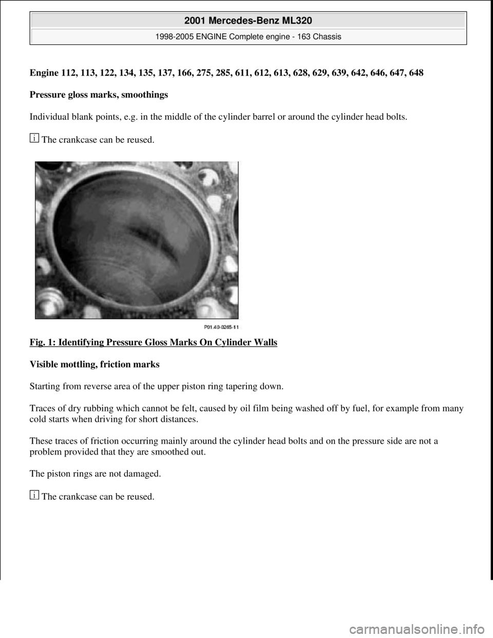
Individual blank points, e.g. in the middle of th e cylinder barrel or around the cylinder head bolts.
The crankcase can be reused.
Fig. 1: Identifying Pressure Gloss Marks On Cylinder Walls
Visible mottling, friction marks
Starting from reverse area of th e upper piston ring tapering down.
Traces of dry rubbing which cannot be felt, caused by oi l film being washed off by fuel, for example from many
cold starts when driving for short distances.
These traces of friction occurring mainly around the cy linder head bolts and on the pressure side are not a
problem provided that they are smoothed out.
The piston rings are not damaged.
The crankcase can be reused.
2001 Mercedes-Benz ML320
1998-2005 ENGINE Complete engine - 163 Chassis
me
Saturday, October 02, 2010 3:17:55 PMPage 2 © 2006 Mitchell Repair Information Company, LLC.
Page 2359 of 4133
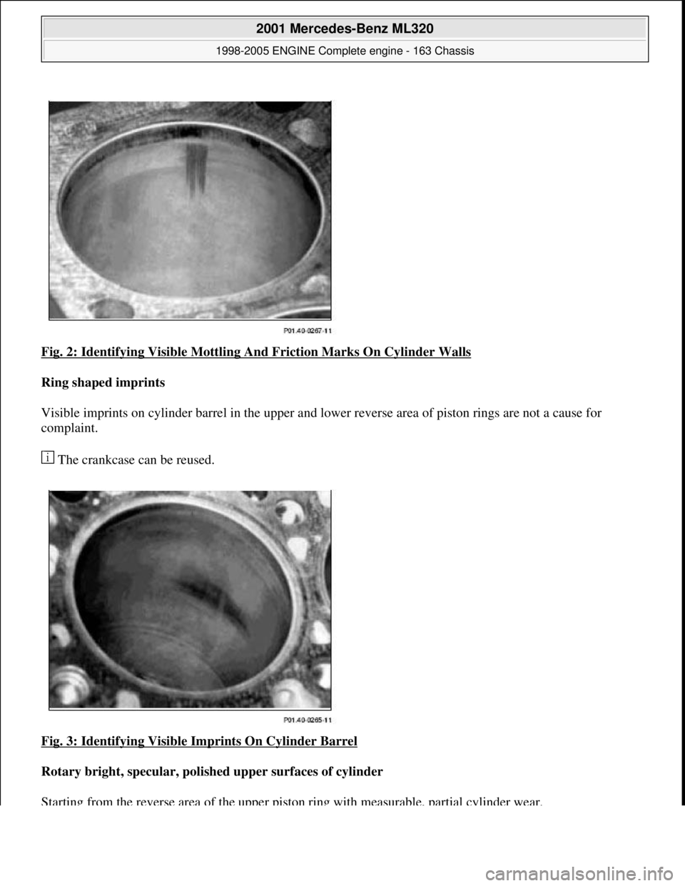
Fig. 2: Identifying Visible Mottling And Friction Marks On Cylinder Walls
Ring shaped imprints
Visible imprints on cylinder barrel in the upper and lo wer reverse area of piston rings are not a cause for
complaint.
The crankcase can be reused.
Fig. 3: Identifying Visible Imprints On Cylinder Barrel
Rotary bright, specular, polish ed upper surfaces of cylinder
Starting from the reverse area of the upper pist on ring with measurable, partial cylinder wear.
2001 Mercedes-Benz ML320
1998-2005 ENGINE Complete engine - 163 Chassis
me
Saturday, October 02, 2010 3:17:55 PMPage 3 © 2006 Mitchell Repair Information Company, LLC.
Page 2385 of 4133
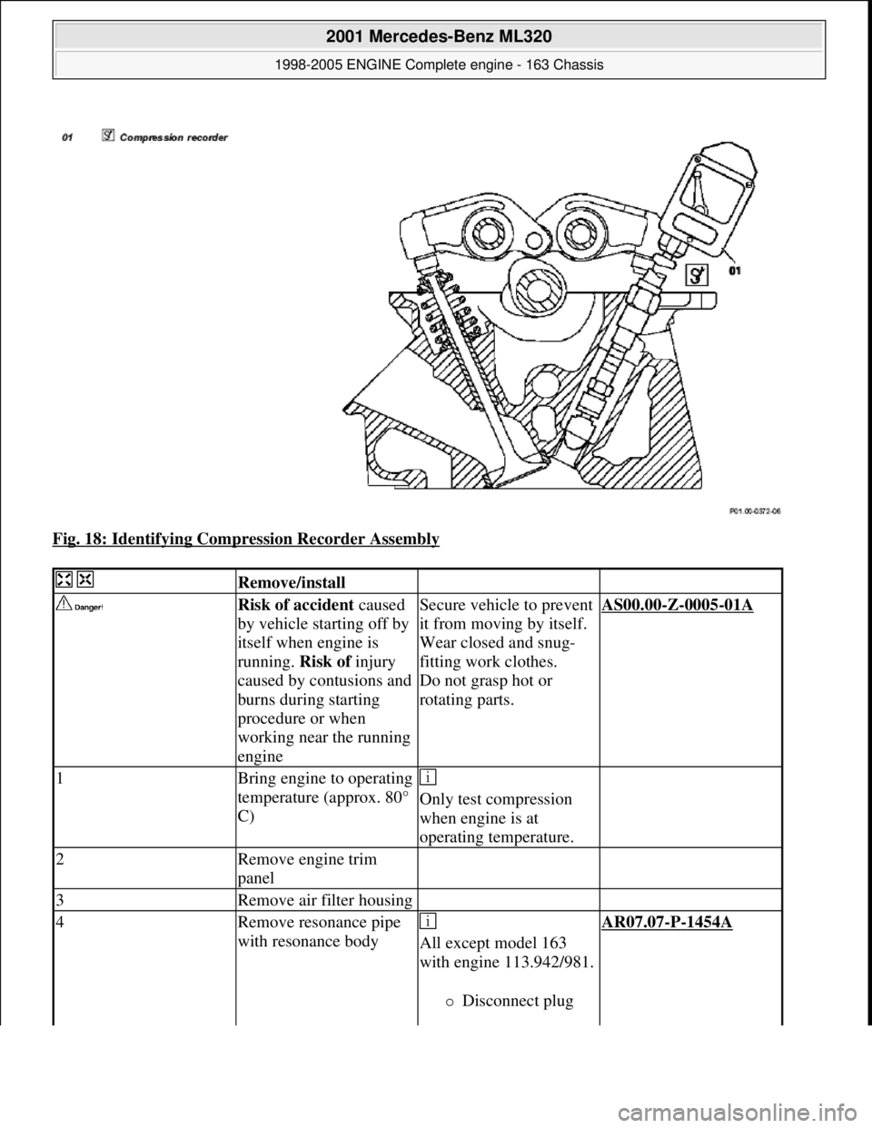
Fig. 18: Identifying Compression Recorder Assembly
Remove/install
Risk of accident caused
by vehicle starting off by
itself when engine is
running. Risk of injury
caused by contusions and
burns during starting
procedure or when
working near the running
engineSecure vehicle to prevent
it from moving by itself.
Wear closed and snug-
fitting work clothes.
Do not grasp hot or
rotating parts.AS00.00-Z-0005-01A
1Bring engine to operating
temperature (approx. 80°
C)
Only test compression
when engine is at
operating temperature.
2Remove engine trim
panel
3Remove air filter housing
4Remove resonance pipe
with resonance body
All except model 163
with engine 113.942/981.
Disconnect plug
AR07.07-P-1454A
2001 Mercedes-Benz ML320
1998-2005 ENGINE Complete engine - 163 Chassis
me
Saturday, October 02, 2010 3:17:56 PMPage 29 © 2006 Mitchell Repair Information Company, LLC.
Page 2389 of 4133
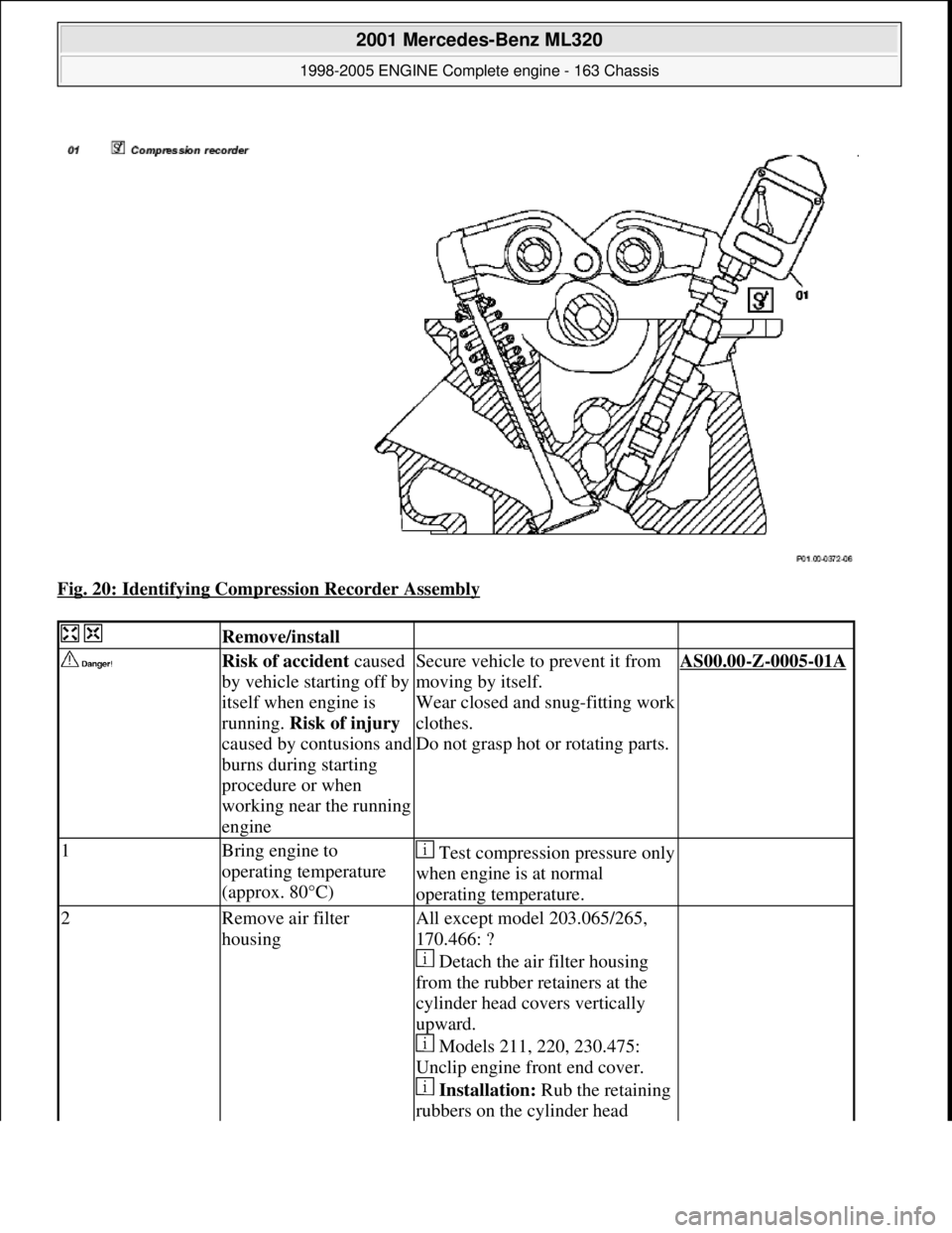
Fig. 20: Identifying Compression Recorder Assembly
Remove/install
Risk of accident caused
by vehicle starting off by
itself when engine is
running. Risk of injury
caused by contusions and
burns during starting
procedure or when
working near the running
engine
Secure vehicle to prevent it from
moving by itself.
Wear closed and snug-fitting work
clothes.
Do not grasp hot or rotating parts.AS00.00-Z-0005-01A
1Bring engine to
operating temperature
(approx. 80°C)Test compression pressure only
when engine is at normal
operating temperature.
2Remove air filter
housingAll except model 203.065/265,
170.466: ?
Detach the air filter housing
from the rubber retainers at the
cylinder head covers vertically
upward.
Models 211, 220, 230.475:
Unclip engine front end cover.
Installation: Rub the retaining
rubbers on the cylinder head
2001 Mercedes-Benz ML320
1998-2005 ENGINE Complete engine - 163 Chassis
me
Saturday, October 02, 2010 3:17:56 PMPage 33 © 2006 Mitchell Repair Information Company, LLC.
Page 2396 of 4133
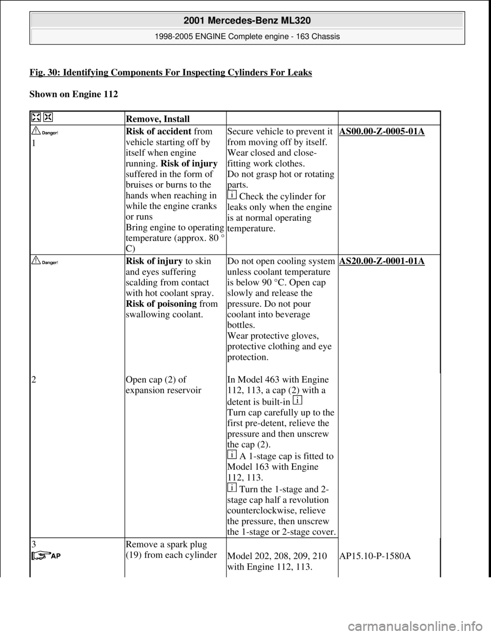
Fig. 30: Identifying Components For Inspecting Cylinders For Leaks
Shown on Engine 112
Remove, Install
1Risk of accident from
vehicle starting off by
itself when engine
running. Risk of injury
suffered in the form of
bruises or burns to the
hands when reaching in
while the engine cranks
or runs
Bring engine to operating
temperature (approx. 80 °
C)Secure vehicle to prevent it
from moving off by itself.
Wear closed and close-
fitting work clothes.
Do not grasp hot or rotating
parts.
Check the cylinder for
leaks only when the engine
is at normal operating
temperature.AS00.00-Z-0005-01A
Risk of injury to skin
and eyes suffering
scalding from contact
with hot coolant spray.
Risk of poisoning from
swallowing coolant.
Do not open cooling system
unless coolant temperature
is below 90 °C. Open cap
slowly and release the
pressure. Do not pour
coolant into beverage
bottles.
Wear protective gloves,
protective clothing and eye
protection.
AS20.00-Z-0001-01A
2Open cap (2) of
expansion reservoirIn Model 463 with Engine
112, 113, a cap (2) with a
detent is built-in
Turn cap carefully up to the
first pre-detent, relieve the
pressure and then unscrew
the cap (2).
A 1-stage cap is fitted to
Model 163 with Engine
112, 113.
Turn the 1-stage and 2-
stage cap half a revolution
counterclockwise, relieve
the pressure, then unscrew
the 1-stage or 2-stage cover.
3Remove a spark plug
(19) from each cylinder
Model 202, 208, 209, 210
with Engine 112, 113.AP15.10-P-1580A
2001 Mercedes-Benz ML320
1998-2005 ENGINE Complete engine - 163 Chassis
me
Saturday, October 02, 2010 3:17:56 PMPage 40 © 2006 Mitchell Repair Information Company, LLC.
Page 2403 of 4133
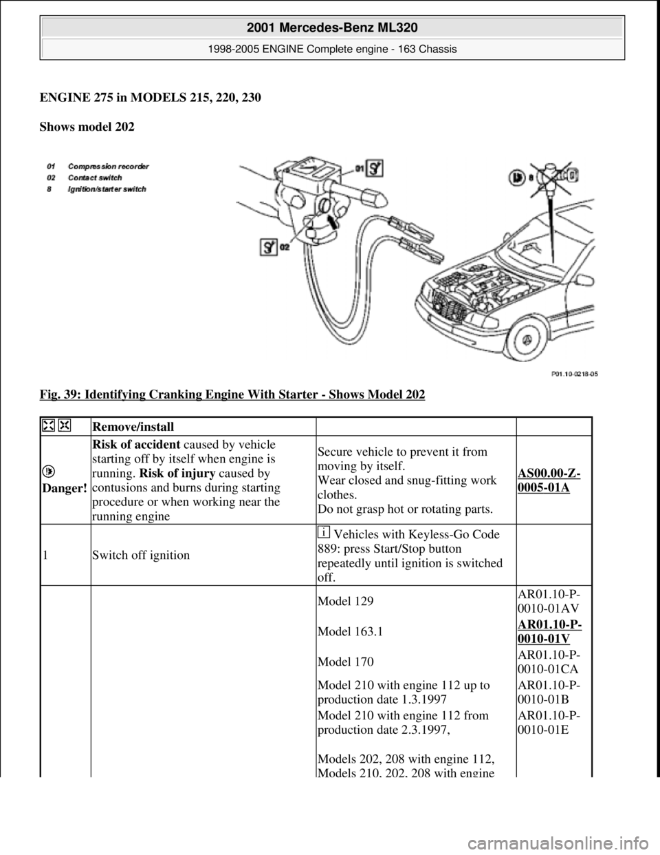
ENGINE 275 in MODELS 215, 220, 230
Shows model 202
Fig. 39: Identifying Cranking Engine With Starter
- Shows Model 202
Remove/install
Danger!
Risk of accident caused by vehicle
starting off by itself when engine is
running. Risk of injury caused by
contusions and burns during starting
procedure or when working near the
running engineSecure vehicle to prevent it from
moving by itself.
Wear closed and snug-fitting work
clothes.
Do not grasp hot or rotating parts.
AS00.00-Z-
0005-01A
1Switch off ignition
Vehicles with Keyless-Go Code
889: press Start/Stop button
repeatedly until ignition is switched
off.
Model 129AR01.10-P-
0010-01AV
Model 163.1AR01.10-P-
0010-01V
Model 170AR01.10-P-
0010-01CA
Model 210 with engine 112 up to
production date 1.3.1997AR01.10-P-
0010-01B
Model 210 with engine 112 from
production date 2.3.1997,AR01.10-P-
0010-01E
Models 202, 208 with engine 112,
Models 210, 202, 208 with engine
2001 Mercedes-Benz ML320
1998-2005 ENGINE Complete engine - 163 Chassis
me
Saturday, October 02, 2010 3:17:56 PMPage 47 © 2006 Mitchell Repair Information Company, LLC.
Page 2412 of 4133
22Disconnect engine
wiring harness AR01.00-P-
2410V
23Remove poly V-belt
(3) Installation: Lock tensioning device with a
drift or pin (diameter 5 mm).
Model 163.154/157/172.AR13.22-P-
1202B
Model 163.174/175.AR13.22-P-
1202BA
24Disconnect
connector from A/C
compressor (10)
25Unbolt AC
compressor (10)
from timing case
cover Attach AC compressor at side in bottom of
engine compartment with lines connected.
*BA83.55-P-
1001-01A
26.1Remove left inner
fender (24) Only engine 113.942 /965 /981.AR88.10-P-
1300GH
27.1Remove shield (25) Only engine 113.942 /965 /981.
28Detach exhaust
system (11) at
exhaust manifold Installation: On vehicles with engine
damage check exhaust sy stem for chips before
assembly and remove any chips present to
prevent later damage
*BA14.10-P-
1002-01B
29Detach exhaust
bracket (12)Support exhaust system for this step.
Installation: Install new nuts.
30Unbolt torque
converter (20) from
starter ring gear(21) Installation: The mounting points (arrows,
black) of the torque converter (20) must be
flush with the three recesses (arrows, white) in
the starting ring gear (21).
*BA27.20-P-
1002-01C
31Disconnect left O2
sensor connector
before TWC
(G3/3x1) and right
O2 sensor connector
before TWC
(G3/4x1) from
transmission Remove cable ties!
32Unscrew starter Do not disconnect electric cables.
*BA15.30-P-
1003-01A
33Unscrew bolts at
transmission bell Engine 112.942/ 970.
Do not unscrew two top bolts at transmission
bell.
Engine 113.942 /965/ 981. Do not unscrew
2001 Mercedes-Benz ML320
1998-2005 ENGINE Complete engine - 163 Chassis
me
Saturday, October 02, 2010 3:17:56 PMPage 56 © 2006 Mitchell Repair Information Company, LLC.