1997 MERCEDES-BENZ ML430 not starting
[x] Cancel search: not startingPage 2050 of 4133
VOLTAGE REGULATOR CONTROL
1. Connect multimeter. See Fig. 10 . Ensure charge indicator light goes out when engine is idling and with
increasing engine speed up to 3000 RPM. Apply load to battery by turning on headlights and noting
reading after 2 minutes.
2. Voltage reading should be 13-14.5 volts. If voltage is not to specification, replace voltage regulator. See
VOLTAGE REGULATOR
under REMOVAL & INSTALLATION. If regulator is okay, replace
generator. See GENERATOR under REMOVAL & INSTALLATION.
2001 Mercedes-Benz ML320
2001-04 STARTING & CHARGING SYSTEMS Generators & Regulators - 163 Chassis
me
Saturday, October 02, 2010 3:20:32 PMPage 16 © 2006 Mitchell Repair Information Company, LLC.
Page 2056 of 4133
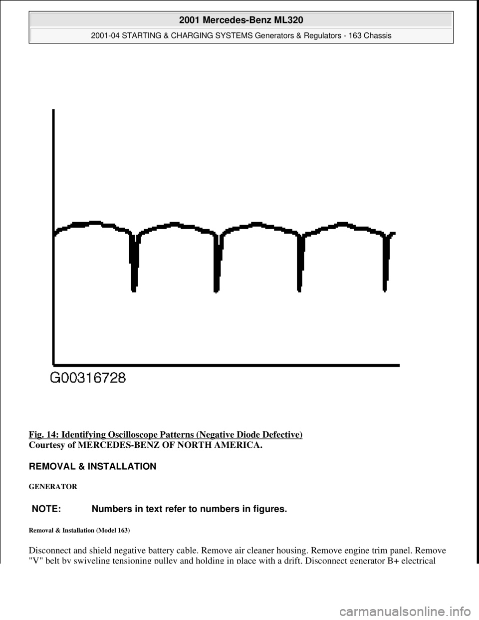
Fig. 14: Identifying Oscilloscope Patterns (Negative Diode Defective)
Courtesy of MERCEDES-BENZ OF NORTH AMERICA.
REMOVAL & INSTALLATION
GENERATOR
Removal & Installation (Model 163)
Disconnect and shield negative battery cable. Remove air cleaner housing. Remove engine trim panel. Remove
"V" belt b
y swiveling tensioning pulley and holding in place with a drift. Disconnect generator B+ electrical
NOTE: Numbers in text refer to numbers in figures.
2001 Mercedes-Benz ML320
2001-04 STARTING & CHARGING SYSTEMS Generators & Regulators - 163 Chassis
me
Saturday, October 02, 2010 3:20:32 PMPage 22 © 2006 Mitchell Repair Information Company, LLC.
Page 2057 of 4133
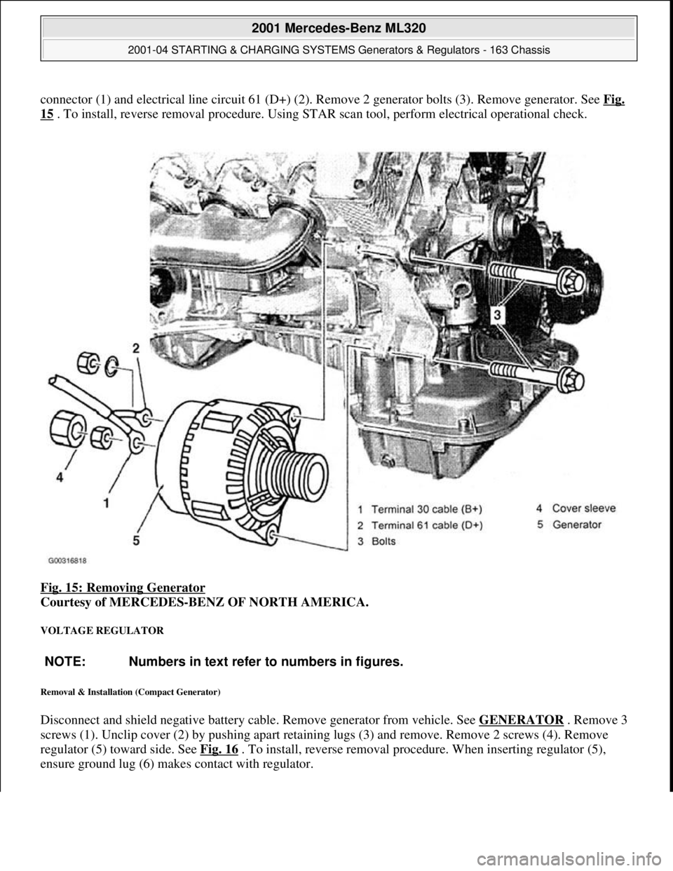
connector (1) and electrical line circuit 61 (D+) (2). Remove 2 generator bolts (3). Remove generator. See Fig.
15 . To install, reverse removal procedure. Using STAR scan tool, perform electrical operational check.
Fig. 15: Removing Generator
Courtesy of MERCEDES-BENZ OF NORTH AMERICA.
VOLTAGE REGULATOR
Removal & Installation (Compact Generator)
Disconnect and shield negative battery cable. Remove generator from vehicle. See GENERATOR . Remove 3
screws (1). Unclip cover (2) by pushing apart retaining lugs (3) and remove. Remove 2 screws (4). Remove
regulator (5) toward side. See Fig. 16
. To install, reverse removal procedure. When inserting regulator (5),
ensure
ground lug (6) makes contact with regulator.
NOTE: Numbers in text refer to numbers in figures.
2001 Mercedes-Benz ML320
2001-04 STARTING & CHARGING SYSTEMS Generators & Regulators - 163 Chassis
me
Saturday, October 02, 2010 3:20:32 PMPage 23 © 2006 Mitchell Repair Information Company, LLC.
Page 2069 of 4133

Danger!
Risk of accident
caused by vehicle starting
off by itself when engine is running.
Risk of
injury
caused by contusions and burns when
working in engine during starting procedure
Secure vehicle to prevent it from moving.
Wear closed and snug-fitting work clothes.
Do not grasp hot or rotating parts.
AS00.00-Z-0005-01A
8
Pour in coolant
Warm up engine by running at moderate
revs. Top up coolant constantly at coolant
expansion reservoir. Close coolant expansion
tank once
coolant temperature is 60-70 °C.
*BF20.00-P-1001-02E
Note on coolant level
Model 124, 129, 140, 163.113, 168, 170, 202,
208, 210, 220, 463
AH20.00-P-1142-01A
9
Inspect cooling system for leaks
AR20.00-P-1010HA
Cooling system
Number
Designation
Engine
612.963
BF20.00-P-1001-02E
Cooling system
Total capacity
Liter
Y
11.0
Filling capacity of anticorrosion/
antifreeze agent down to
-37 °C
Liter
Y
5.5
Filling capacity of anticorrosion/
antifreeze up to -45 °C
Liter
Y
6.25
Specifications for Operating
Fluids
SheetBB00.40-P-0310-01A
SheetBB00.40-P-0325-00A
Copyright DaimlerChrysler AG 12.05.2006 CD-Ausgabe G/10/04 . This WIS print-out will not be recorde
d by Modification services.
Page 2
Page 2076 of 4133

Danger!
Risk of accident
caused by vehicle starting
off by itself when engine is running.
Risk of
injury
caused by contusions and burns when
working in engine during starting procedure
Secure vehicle to prevent it from moving.
Wear closed and snug-fitting work clothes.
Do not grasp hot or rotating parts.
AS00.00-Z-0005-01A
8
Pour in coolant
Warm up engine by running at moderate
revs. Top up coolant constantly at coolant
expansion reservoir. Close coolant expansion
tank once
coolant temperature is 60-70 °C.
*BF20.00-P-1001-02E
Note on coolant level
Model 124, 129, 140, 163.113, 168, 170, 202,
208, 210, 220, 463
AH20.00-P-1142-01A
9
Inspect cooling system for leaks
AR20.00-P-1010HA
Cooling system
Number
Designation
Engine
612.963
BF20.00-P-1001-02E
Cooling system
Total capacity
Liter
Y
11.0
Filling capacity of anticorrosion/
antifreeze agent down to
-37 °C
Liter
Y
5.5
Filling capacity of anticorrosion/
antifreeze up to -45 °C
Liter
Y
6.25
Specifications for Operating
Fluids
SheetBB00.40-P-0310-01A
SheetBB00.40-P-0325-00A
Copyright DaimlerChrysler AG 28.05.2006 CD-Ausgabe G/10/04 . This WIS print-out will not be recorde
d by Modification services.
Page 2
Page 2089 of 4133

29
Slacken cylinder head bolts (21) in stages,
unscrew
Loosen cylinder head bolts according to
loosening schematic only after engine has
cooled down to prevent cylinder head from
distorting.
AR01.30-P-5800-09B
Installation:
Observe tightening pattern
and tightening instructions of cylinder head
bolts.
Oil thread and head contact surface of
cylinder head bolts.
AR01.30-P-5800-07B
Screwdriver insert
*000589031000
Screwdriver insert
*000589041000
*BA01.30-P-1001-01D
30
Remove cylinder head
Installation:
On Engine 112/113 observe
porous points in the left and right cylinder
head. If porous points are present, sealant
must be applied to the cylinder head gasket.
Notes on application of sealant to cylinder
head gasket.
Engine 112, 113
AH01.30-P-1000-04VA
The sealant must be applied within
10 minutes.
Loctite 5900 sealant.
*BR00.45-Z-1015-01A
31
Inspect version of cylinder head gasket
Assignment of cylinder head gasket
Information for assigning the cylinder head
gaskets
Engine 112, 113
AH01.30-P-1000-06V
32
Check cylinder head bolts (21)
AR01.30-P-5800-03B
*BE01.30-P-1001-04B
33
Clean sealing surfaces, inspect for cracks,
shrink holes and flatness, clean threaded
holes.
Pay attention to dowel sleeves (26) for
locating the cylinder head.
Sealing surfaces of crankcase and
cylinder head are provided with an 0.8 mm
thick silicone layer during series production.
At the time of repair installation, silicone
sealant is applied to the sealing area only in
case of any shrink holes.
The sealant must be applied within
10 minutes.
Loctite 5900 sealant.
*BR00.45-Z-1015-01A
34
Install in the reverse order
Danger!
Risk of accident
caused by vehicle starting
off by itself when engine is running.
Risk of
injury
caused by contusions and burns when
working in engine during starting procedure
Secure vehicle to prevent it from moving.
Wear closed and snug-fitting work clothes.
Do not grasp hot or rotating parts.
AS00.00-Z-0005-01A
35
Run engine and inspect for leaks
36
Inspect cooling system for leaks
Warm up engine to operating temperature
and then inspect cooling system or leaks.
AR20.00-P-1010HA
37
Read out and erase fault memory
Stored faults which can result from cables
being disconnected or from simulation during
removal and installation or test work, have to
be processed and erased in the fault
memories after completing the work:
#
Diagnosis Manual Volume 2 Index 0:
Connecting and using test equipment.
Cylinder head/cylinder head bolts
Number
Designation
Engine
112.910/911/912/
913/914/915/
916/917/920/
921/922/923/
940/941/942/
943/944/945/
946/947/949/
951/953/954/
955/960/961/
970/972/973/975
Engine
113.940/941/
942/943/944/
945/946/948/
960/961/962/
963/965/966/
967/968/969/
980/981/982/
984/986/987/
988/990/991/
992/993
BE01.30-P-1001-04B
Cylinder head bolt
Thread diameter
M
1111
Length (L) when new
mm
141.5141.5
Length (L)
mm
T
144.5
T
144.5
Copyright DaimlerChrysler AG 20.05.2006 CD-Ausgabe G/10/04 . This WIS print-out will not be recorde
d by Modification services.
Page 5
Page 2097 of 4133

29
Slacken cylinder head bolts (21) in stages,
unscrew
Loosen cylinder head bolts according to
loosening schematic only after engine has
cooled down to prevent cylinder head from
distorting.
AR01.30-P-5800-09B
Installation:
Observe tightening pattern
and tightening instructions of cylinder head
bolts.
Oil thread and head contact surface of
cylinder head bolts.
AR01.30-P-5800-07B
Screwdriver insert
*000589031000
Screwdriver insert
*000589041000
*BA01.30-P-1001-01D
30
Remove cylinder head
Installation:
On Engine 112/113 observe
porous points in the left and right cylinder
head. If porous points are present, sealant
must be applied to the cylinder head gasket.
Notes on application of sealant to cylinder
head gasket.
Engine 112, 113
AH01.30-P-1000-04VA
The sealant must be applied within
10 minutes.
Loctite 5900 sealant.
*BR00.45-Z-1015-01A
31
Inspect version of cylinder head gasket
Assignment of cylinder head gasket
Information for assigning the cylinder head
gaskets
Engine 112, 113
AH01.30-P-1000-06V
32
Check cylinder head bolts (21)
AR01.30-P-5800-03B
*BE01.30-P-1001-04B
33
Clean sealing surfaces, inspect for cracks,
shrink holes and flatness, clean threaded
holes.
Pay attention to dowel sleeves (26) for
locating the cylinder head.
Sealing surfaces of crankcase and
cylinder head are provided with an 0.8 mm
thick silicone layer during series production.
At the time of repair installation, silicone
sealant is applied to the sealing area only in
case of any shrink holes.
The sealant must be applied within
10 minutes.
Loctite 5900 sealant.
*BR00.45-Z-1015-01A
34
Install in the reverse order
Danger!
Risk of accident
caused by vehicle starting
off by itself when engine is running.
Risk of
injury
caused by contusions and burns when
working in engine during starting procedure
Secure vehicle to prevent it from moving.
Wear closed and snug-fitting work clothes.
Do not grasp hot or rotating parts.
AS00.00-Z-0005-01A
35
Run engine and inspect for leaks
36
Inspect cooling system for leaks
Warm up engine to operating temperature
and then inspect cooling system or leaks.
AR20.00-P-1010HA
37
Read out and erase fault memory
Stored faults which can result from cables
being disconnected or from simulation during
removal and installation or test work, have to
be processed and erased in the fault
memories after completing the work:
#
Diagnosis Manual Volume 2 Index 0:
Connecting and using test equipment.
Cylinder head/cylinder head bolts
Number
Designation
Engine
112.910/911/912/
913/914/915/
916/917/920/
921/922/923/
940/941/942/
943/944/945/
946/947/949/
951/953/954/
955/960/961/
970/972/973/975
Engine
113.940/941/
942/943/944/
945/946/948/
960/961/962/
963/965/966/
967/968/969/
980/981/982/
984/986/987/
988/990/991/
992/993
BE01.30-P-1001-04B
Cylinder head bolt
Thread diameter
M
1111
Length (L) when new
mm
141.5141.5
Length (L)
mm
T
144.5
T
144.5
Copyright DaimlerChrysler AG 20.05.2006 CD-Ausgabe G/10/04 . This WIS print-out will not be recorde
d by Modification services.
Page 5
Page 2156 of 4133
NOTES ON AVOIDING DAMAGE TO IGNITION SYSTEM - AH15.10-P-0002-01D
Engine 104, 111, 112, 113, 119, 120, 156, 271
To avoid damage to control unit connect and disconnect the two connectors on control unit only when
ignition is switched off.
Terminal 1 of ignition coils must not be short-circuited to GND, e.g. as anti-theft protection.
Install only original ignition system components.
Do not operate ignition system at starting speed unless all of the ignition cables are connected.
No tests such as holding ignition cable 4 at a distance to GND, unplugging a spark plug connector or
pulling cable 4 out of the ignition coils, may be performed at starting speed or when the engine is
running.
Every high voltage circuit must be loaded with at least 2 kohms (spark plug connector).
If it is necessary to test the ignition spark when providing roadside assistance, this must only be done with
a spark plug at a cylinder ignition cable. Ensure that the spark plug has good contact to ground.
Before working at cranking speed, e.g. checking compression pressure, switch off ignition and disconnect
connector "2" from control unit.
Engine 120 has two fuel injection and ignition systems.
Use of testers
Only connect and disconnect secondary measuring sensor to corresponding ignition cables when vertical
engine and ignition are switched off.
If the shot-circuit protection is operated (cylinder comparison) and the engine stays upright, it is not
possible to conduct the test with this test instrument.
Do not connect test lamp to ignition coil terminals 1 and 15.
NOTES ON IGNITION COIL CHARACTERISTICS OF IGNITION SYSTEMS - AH15.10-P-1001-01A
Engine 104, 111, 112, 113, 119, 120
In the case of the twin-spark ignition coil with kV pickup in ignition systems ME-SFI 2.1 and HFM-SFI, no
measurement facilit
y exists at the ignition coil using the kV pickup although a kV pickup is fitted. It is only
damage to ignition system
Notes on avoiding
damage to ignition systemENGINE 104, 111, 112, 113,
119, 120, 156, 271, 112 mit
Benzin-Einspritz- und
Zundsystem MEAH15.10-P-0002-01D
Notes for ceramic glow
plugsENGINE 646.8, 642AH15.20-P-0001-01A
2001 Mercedes-Benz ML320
1998-2005 ENGINE Electrical System - Engine - 163 Chassis
me
Saturday, October 02, 2010 3:18:54 PMPage 2 © 2006 Mitchell Repair Information Company, LLC.