1997 MERCEDES-BENZ ML350 change time
[x] Cancel search: change timePage 2875 of 4133
clothing, safety gloves and eye protection
Potential risks
Risk of death
Risk of explosion caused by liquefied petroleum gas leaking out of the system in closed rooms or when gas the
tank is overheated due to work being done.
Risk of burn injuries caused by explosions.
Risk of frostbite to skin and body parts caused by liquefied petroleum gas spraying out and by coming into
contact with components that are near the valve when the tank is being emptied. Risk of poisoning or risk of
suffocation caused by inhaling liquefied petroleum gas.
Safety instructions/precautions
Wear protective clothing, safety gloves and eye protection
Keep suitable fire extinguishing equipment at hand
Keep any flammable materials and objects away from the equipment
Avoid making any sparks
Perform a fire check of the surroundings after work has carried out
Never perform work in closed rooms
Before commencing any work, ensure that all sources of ignition have been eliminated. Ensure adequate
ventilation of the immediate area around the vehicle.
Adequate ventilation means an exchange of air at least 3 times an hour at a distance of 3 meters from the gas
shutoff valve.
Close the gas shutoff valves at the compressed-gas tanks before commencing repair work.
Close off gas tank valve if vehicle is to remain in closed rooms, e.g. in halls or garages, for longer periods of
time.
Maintenance and repair work may only be carried out by specially trained personnel.
Due to the fact that explosions can occur when the gas system has leaks, a leak test must be performed before
restarting the system after repairs have been done in which the pipes and lines of the gas system have been
opened.
In the Federal Republic of Germany, this leak test can only be performed by specially trained DVFG personnel
as per the DVGW Work Sheet G 607.
(DVFG - German Liquefied Petroleum Gas Association)
2004 Mercedes-Benz ML350
1998-2005 GENINFO Overall vehicle - 163 Chassis
me
Saturday, October 02, 2010 3:47:48 PMPage 230 © 2006 Mitchell Repair Information Company, LLC.
Page 3151 of 4133
The ATF correspond to the valid GM specification Dexron III, Voith lubricant lists G 607 and ZF
lubricant specification TE-ML 14.
3.9 Automatic transmission fluid (ATF), Sheet 236.10, for MB automatic transmissions with and without
regulated torque converter lockup clutch (GKUB) in passenger vehicles. This ATF is provided ex works
as lifetime oil in all MB automatic transmissions with regulated torque converter lockup clutch - model
series 722.6 - in passenger cars. For repair work, only the ATF quality specified in sheet 236.10 may be
used for refilling in this new generation of automatic transmissions, and this can be obtained in a 1 liter
container under the part no. 001 989 2103.
All MB automatic transmissions without regulated torque converter lockup clutch in passenger vehicles
can either be filled with the ATF according to Sheet 236.10 or the ATF according to the Sheets
236.1/.6/.7/.81/.9.
3.10 Automatic transmission fluids (ATF), sheet 236.11 , for ZF automatic transmission "IF 4 HP 20"
and the automatic transmission oil circuit of the VW automatic transmission "AG4"
The approved ATF are usually only used in the event of repair or for refilling.
3.11 Automatic transmission fluids (ATF), sheet 236.12 , for 7-gear automatic transmission oils (ATF), is
also downwards-compatible for all 5-gear automatic transmissions.
3.12 Sheet 236.13 , repair solution for MB automatic transmissions without regulated torque converter
lockup clutch in passenger cars with the complaint of "double harsh engagement after engaging drive
mode D", the MB automatic transmission fluid - part no:.
A 001 989 2303 11 - and/or the ATF "ATF MB 274" from Exxon Mobil Corporation, Fairfax, Virginia,
USA, must be used. The ATF "Shell ATF MB" and/or the MB automatic transmission fluid with the part
no.: A 001 989 0703" previously approved for the above-mentioned application must no longer be used,
but can be used up as an ATF for oil changes necessary as a result of maintenance.
3.13 Automatic transmission fluids (ATF), sheet 236.20 , for CVT transmissions that are used in
Mercedes-Benz A-class and B-Class vehicles with CVT transmission, model 169, 245 with transmission
722.8
SPECIFIED GEAR OILS (CARS, CROSS-COUNTRY VEHICLES) - SURVEY - BB00.40-P-0231-01A
• Should be used
o Can be used
Passenger car, sheets 235.0 to 235.61
Major assemblySAE gradeSheet No.
235.0235.1235.7235.10235.15235.61
Front axle
(4Matic)85 W-90,
90o •
2004 Mercedes-Benz ML350
1998-2005 GENINFO Overall vehicle - 163 Chassis
me
Saturday, October 02, 2010 3:47:56 PMPage 506 © 2006 Mitchell Repair Information Company, LLC.
Page 3185 of 4133

AD54.30-P-2000-02GC
Notes on HHT previous knowledge diagnosis
IC
HHT :
The instrument cluster and active service system (ASSYST) sub-
function are checked with HHT, there being the choice of the
following functions for this:
1. Control module version
2. Fault memory
3. Actual values
4. Actuations
5. Control module adaptation
Additional information on test items 2, 3 and 5 can be called up using
the INPUT key
Control module adaptation
The following alternatives are available in the HHT under control
module adaptation:
1.)
Read out coding and transfer to new instrument cluster. IC and
ASSYST.
2.)
Read out/change codings e.g.:
Engine and national variants,
version of fuel tank,
special equipment etc.
3.)
Settings:
1
Clock
2
Put forward kilometer reading
3
Put back kilometer reading
4
Oil change
5
Reset oil change initiated inadvertently
6
Active Service System
7
Enter times with battery disconnected
8
Set minimum oil warning
Before replacing a defective instrument cluster, readout the existing
variant codings (driving data and instrument cluster data) and store in
the HHT on an interim basis. Read in the values stored on an interim
basis again after installing the new instrument cluster.
If it is not possible to read out the stored variant coding, all variant
codings must be input manually (menu-assistance in HHT).
When installing an instrument cluster on an experimental basis, do
not put forward the kilometer reading as it cannot be put back later.
Copyright DaimlerChrysler AG 05.06.2006 CD-Ausgabe G/10/04 . This WIS print-out will not be recorde
d by Modification services.
Page 1
Page 3191 of 4133

Valve seal not okay :
#
3
Remove/install/replace valve seal.
AR05.30-P-3500B
Cause 6:
Remedy 6:
00 001 70
1.5 mm hole missing on individual right
cylinder head covers at connection to
crankcase ventilation.
1
Check cylinder head cover
Up to production 06/1999.
Crankcase ventilation out of order, engine can
sludge up and consume oil as a result
Cylinder head cover not okay:
#
2
Remove/install/replace cylinder head
cover.
ENGINE
112
Air cleaner positioned on engine
side.
ENGINE
113
Air cleaner positioned on engine
side.
AR01.20-P-5014BV
ENGINE
112
Air cleaner positioned on engine side
ENGINE
113
Air cleaner positioned on engine side
AR01.20-P-5014B
Cause 7:
Remedy 7:
00 001 70
Engine oil sludging due to excessively long
engine oil change intervals
Service information: Oil sludge
SI18.00-P-0010A
If the service interval according to
ASSYST is exceeded, the engine oil sludges
up sooner or later depending on the oil
quality, type of operation and operating time.
Engine consumes oil.
See Service Information.
1
Print out ASSYST printout.
2
Check oil change intervals
3
Inform vehicle owner.
4
Remove/install/replace piston rings.
AR03.10-P-7311BV
Disassemble and clean sludged engines
completely because dirty oil usually gets into
clean-oil side due to clogged oil filter.
Cause 8:
Remedy 8:
00 001 70
Piston rings sticky or have coke deposits from
engine oils (e.g. API-S in USA) in connection
with regionally poor fuel quality.
Always use engine oils according to
Specifications for Operating Fluids 229.3, do
not add special additives to engine oil and fuel
BB00.40-P-0229-03A
1
Remove/install/replace piston rings.
AR03.10-P-7311BV
Cause 9:
Remedy 9:
00 001 70
Piston ring wear due to excessive
contamination/dust (model 163) through air
intake system.
1
Remove/install/replace gaskets on air
intake line and distribution element of
partial load ventilation.
e.g. due to incorrect assembly after
workshop visit or embrittlement of gaskets
The distribution element with optimized
material will be available as of 11/ 2000 as a
standard feature.
2
Remove/install/replace intake module.
Exterior oil loss, e.g. due to cast iron
porosity on left side of crankcase in area of
engine support is not considered to be oil
consumption
In the event of a customer complaint
regarding the engine oil consumption, always
determine the oil consumption definitely
because the oil indicator lamp can come on
due to other causes (e.g. defective oil sensor).
Commercially available tools
(see Workshop Equipment Manual)
Number
Designation
Make (e. g.)
Order number
WH58.30-Z-1009-05A
Flexible inspection light
Scope of supply 1 (complete unit):
-glass fiber optical fiber
-light projector
-230 V, storage case
-operating instructions
-graphics protocol
Richard Wolf GmbH
Pforzheimerstr. 32
D-75438 Knittlingen
Karl Storz GmbH
Mittelstr. 8
D-78532 Tuttlingen
1.00565.00
80902
WH58.30-Z-1010-05A
Flexible inspection light
Scope of delivery 2 (for workshops which already have an approved
Wolf or Storz inspection light):
-storage case
-operating instructions
-pictures protocol
Richard Wolf GmbH
Pforzheimerstr. 32
D-75438 Knittlingen
Karl Storz GmbH
Mittelstr. 8
D-78532 Tuttlingen
7.05065.00
K03506AJ
Copyright DaimlerChrysler AG 20.05.2006 CD-Ausgabe G/10/04 . This WIS print-out will not be recorde
d by Modification services.
Page 2
Page 3289 of 4133
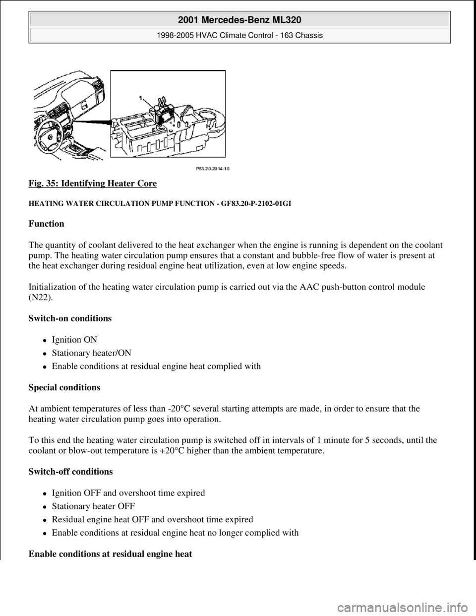
Fig. 35: Identifying Heater Core
HEATING WATER CIRCULATION PUMP FUNCTION - GF83.20-P-2102-01GI
Function
The quantity of coolant delivered to the heat exchanger when the engine is running is dependent on the coolant
pump. The heating water circulation pump ensures that a constant and bubble-free flow of water is present at
the heat exchanger during residual engine heat utilization, even at low engine speeds.
Initialization of the heating water circulation pump is carried out via the AAC push-button control module
(N22).
Switch-on conditions
Ignition ON
Stationary heater/ON
Enable conditions at residual engine heat complied with
Special conditions
At ambient temperatures of less than -20°C several starting attempts are made, in order to ensure that the
heating water circulation pump goes into operation.
To this end the heating water circulation pump is switched off in intervals of 1 minute for 5 seconds, until the
coolant or blow-out temperature is +20°C higher than the ambient temperature.
Switch-off conditions
Ignition OFF and overshoot time expired
Stationary heater OFF
Residual engine heat OFF and overshoot time expired
Enable conditions at residual engine heat no longer complied with
Enable conditions at residual engine heat
2001 Mercedes-Benz ML320
1998-2005 HVAC Climate Control - 163 Chassis
me
Saturday, October 02, 2010 3:23:15 PMPage 45 © 2006 Mitchell Repair Information Company, LLC.
Page 3325 of 4133
The residual engine heat utilization system allows the vehicle to be heated even when the ignition is
switched OFF. To do so the system utilizes the residual heat from the engine and guides it via the
blower into the passenger compartment. The heating water circulation pump ensures that the
coolant is properly circulated.
Automatic air conditioning push-button control module
The automatic air conditioning can be operated by the driver using various tip switches. Apart from this
the push-
button control module reads in different sensor signals, processes them and controls components
in the automatic air conditioning.
Rear ventilation control panel
The operator can intervene in the automatic regulation of the rear ventilation through the automatic air
conditioning by using the rear ventilation control panel and adjust it accordingly to suit needs at any
given time. With the aid of the air distribution switch and blower switch the operator can accommodate
his/her own wishes. The correspondingly altered function is then no longer regulated by the automatic air
conditioning.
By pressing the automatic control button the manually initiated settings can be reset and thus regulated
again by the automatic air conditioning.
Regulation of the air quantity and air distribution ensues thus solely by way of the automatic air
conditioning push-button control module.
Heater circuit
Coolant is heated by the engine. Subsequently, the heated coolant is then routed through the heat exchanger,
where the heat is dissipated to the air in the passenger compartment. The heater return line, in which the heating
water circulation pump is located, takes the coolant back to the coolant pump.
The heating water circulation pump ensures that the coolant is properly circulated.
The coolant flows through the heat exchanger permanently.
Depending upon the desired in-car temperature, regulation is conducted over the blending air flaps, which are
operated by the blending air flap actuator motor.
Heater operation with heater booster in vehicles with OM 612.963
In vehicles equipped with direct-injection diesel engines, an electrical heater booster is additionally installed in
the evaporator housing downstream of the heat exchanger, in order to compensate the heater output deficit
which occurs in the case of certain operating conditions.
The 3 heating elements in the heater booster are supplied with current, as a result of which they are heated and
start to glow. As a result of the structural conditions, it is ensured that the drawn in fresh air flows directly past
the electric heater booster, and is therefore heated.
2001 Mercedes-Benz ML320
1998-2005 HVAC Climate Control - 163 Chassis
me
Saturday, October 02, 2010 3:23:16 PMPage 81 © 2006 Mitchell Repair Information Company, LLC.
Page 3397 of 4133
OFF . To this end the system uses the residual heat of the engine. The residual engine heat is dissipated to the
coolant and routed through the heat exchanger with the aid of the heating water circulation pump. The air drawn
in by the blower motor is routed around the heat exchanger, whereby it is then warmed up. The heated air is
then routed over the air outlets into the passenger compartment.
The residual engine heat utilization system can only be used when the ignition is switched OFF.
Once the Rest push-button ( ) on the AAC push-button control module (N22) has been pressed the
following program sequence is run:
Blending air flaps are automatically controlled
Heating water circulation pump ON
The blower's control voltage is limited to a maximum value of 5 Volt.
End of program
Pressing the Rest push-button ( )
Timeout of 30 minutes period (repeated operation possible)
Protection against undervoltage at a battery voltage of less than 11 V (LED flashes)
Ignition ON
During the residual engine heat utilization function no function keys are accepted apart from the Rest push-
button ( ) and the set point adjusters.
SAFETY PRECAUTIONS
RISK OF EXPLOSION CAUSED BY WELDING OR SOLDERING WORK ON CLOSED AIR CONDITIONING SYSTEM.
RISK OF POISONING CAUSED BY INHALING OVERHEATED REFRIGERANT VAPORS. RISK OF INJURY TO SKIN AND
EYES CAUSED BY CONTACT WITH LIQUID REFRIGERANT. - AS83.00-Z-0001-01A
Never perform welding work on or near a closed air conditioning system. No smoking or open flames.
Wear safety glasses and protective gloves. Work only in well ventilated areas. Carry out repair work on
the air conditioning system circuit only after the system has been discharged.
Potential risks
Risk of explosion
When closed air conditionin
g systems (charged or empty) become heated, high pressures are produced that can
Rest push-button, location/task/function GF83.40-P-2148GI
Heating water circulation pump, location/task/ function GF83.20-P-2109GI
Heating system heat exchanger, location/ purpose/function GF83.20-P-2108GC
Blower motor, location/task/design/function GF83.10-P-2170GI
Blending air flap actuator, location/task/function GF83.57-P-2112GI
2001 Mercedes-Benz ML320
1998-2005 HVAC Climate Control - 163 Chassis
me
Saturday, October 02, 2010 3:23:17 PMPage 153 © 2006 Mitchell Repair Information Company, LLC.
Page 3408 of 4133
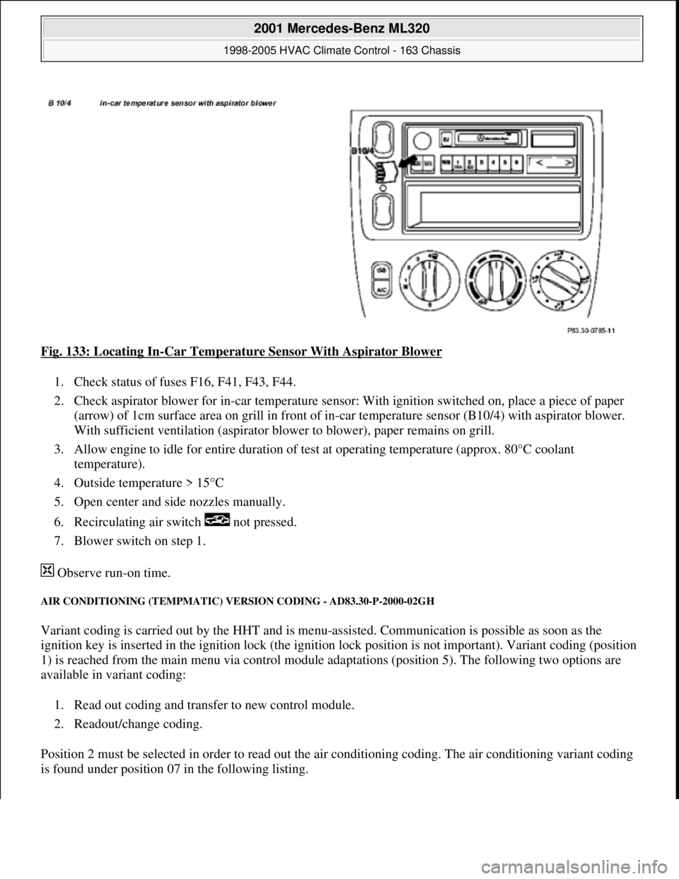
Fig. 133: Locating In-Car Temperature Sensor With Aspirator Blower
1. Check status of fuses F16, F41, F43, F44.
2. Check aspirator blower for in-car temperature sensor: With ignition switched on, place a piece of paper
(arrow) of 1cm surface area on grill in front of in-car temperature sensor (B10/4) with aspirator blower.
With sufficient ventilation (a spirator blower to blower), paper remains on grill.
3. Allow engine to idle for entire duration of test at operating temperature (approx. 80°C coolant
temperature).
4. Outside temperature > 15°C
5. Open center and side nozzles manually.
6. Recirculating air sw itch not pressed.
7. Blower switch on step 1.
Observe run-on time.
AIR CONDITIONING (T EMPMATIC) VERSION CO DING - AD83.30-P-2000-02GH
Variant coding is carried out by the HHT and is menu -assisted. Communication is possible as soon as the
ignition key is inserted in the ignition lock (the igniti on lock position is not important). Variant coding (position
1) is reached from the main menu via control module adaptations (position 5). The following two options are
available in variant coding:
1. Read out coding and transfer to new control module.
2. Readout/change coding.
Position 2 must be selected in order to read out th e air conditioning coding. The air conditioning variant coding
is found under position 07 in the following listing.
2001 Mercedes-Benz ML320
1998-2005 HVAC Climate Control - 163 Chassis
me
Saturday, October 02, 2010 3:23:17 PMPage 164 © 2006 Mitchell Repair Information Company, LLC.