1997 MERCEDES-BENZ ML350 change time
[x] Cancel search: change timePage 2296 of 4133
i040*WH58.30-Z-
1003-28A
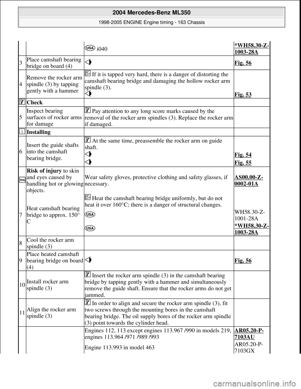
3Place camshaft bearing
bridge on board (4) Fig. 56
4
Remove the rocker arm
spindle (3) by tapping
gently with a hammer If it is tapped very hard, th ere is a danger of distorting the
camshaft bearing bridge and da maging the hollow rocker arm
spindle (3).
Fig. 53
Check
5
Inspect bearing
surfaces of rocker arms
for damage Pay attention to any long score marks caused by the
removal of the rocker arm spindl es (3). Replace the rocker arm
if damaged.
Installing
6
Insert the guide shafts
into the camshaft
bearing bridge. At the same time, preassemble the rocker arm on guide
shaft.
Fig. 54
Fig. 55
Risk of injury to skin
and eyes caused by
handling hot or glowing
objects.
Wear safety gloves, protective cl othing and safety glasses, if
necessary.AS00.00-Z-
0002-01A
7
Heat camshaft bearing
bridge to approx. 150°
C
Heat the camshaft bearing bridge uniformly, but do not
heat it over 160°C; there is a danger of structural changes.
WH58.30-Z-
1001-28A
*WH58.30-Z-
1003-28A
8Cool the rocker arm
spindle (3)
9
Place heated camshaft
bearing bridge on board
(4) Fig. 56
10Install rocker arm
spindle (3)
Insert the rocker arm spindle (3) in the camshaft bearing
bridge by tapping gently with a hammer and simultaneously
remove the guide shaft. Ensure that the rocker arms do not get
jammed.
11Align the rocker arm
spindle (3)
In order to align and secure the rocker arm spindle (3), fit
two screws through the mount ing bores in the camshaft
bearing bridge. The oil supply bores of the rocker arm spindle
(3) point towards the cylinder head.
Engines 112, 113 except engines 113.967 /990 in models 219,
engines 113.964 /971 /989 /993AR05.20-P-
7103AU
Engine 113.993 in model 463AR05.20-P-
7103GX
2004 Mercedes-Benz ML350
1998-2005 ENGINE Engine timing - 163 Chassis
me
Saturday, October 02, 2010 3:39:38 PMPage 55 © 2006 Mitchell Repair Information Company, LLC.
Page 2650 of 4133
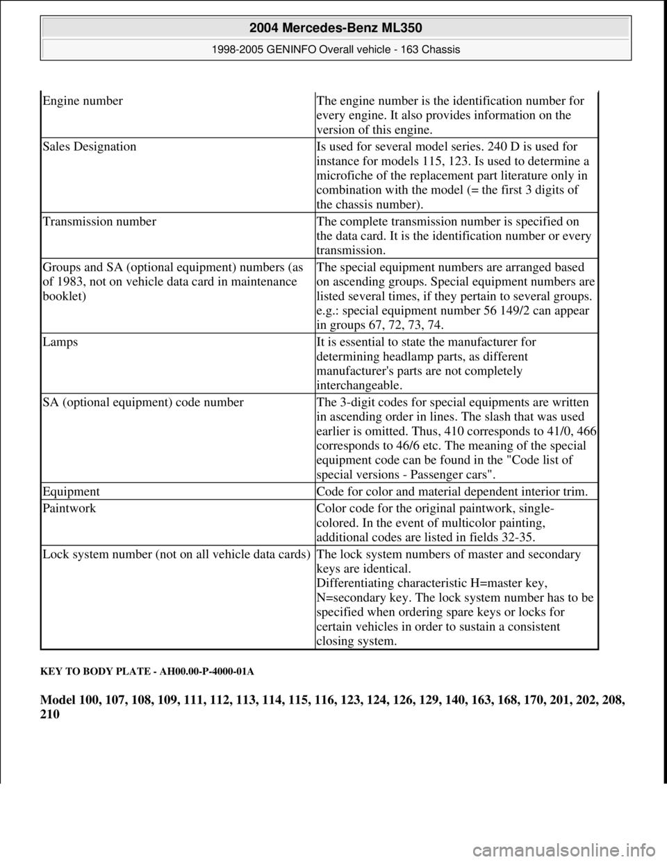
KEY TO BODY PLATE - AH00.00-P-4000-01A
Model 100, 107, 108, 109, 111, 112, 113, 114, 115, 116, 123, 124, 126, 129, 140, 163, 168, 170, 201, 202, 208,
210
Engine numberThe engine number is the identification number for
every engine. It also provides information on the
version of this engine.
Sales DesignationIs used for several model series. 240 D is used for
instance for models 115, 123. Is used to determine a
microfiche of the replacement part literature only in
combination with the model (= the first 3 digits of
the chassis number).
Transmission numberThe complete transmission number is specified on
the data card. It is the identification number or every
transmission.
Groups and SA (optional equipment) numbers (as
of 1983, not on vehicle data card in maintenance
booklet)The special equipment numbers are arranged based
on ascending groups. Special equipment numbers are
listed several times, if they pertain to several groups.
e.g.: special equipment number 56 149/2 can appear
in groups 67, 72, 73, 74.
LampsIt is essential to state the manufacturer for
determining headlamp parts, as different
manufacturer's parts are not completely
interchangeable.
SA (optional equipment) code numberThe 3-digit codes for special equipments are written
in ascending order in lines. The slash that was used
earlier is omitted. Thus, 410 corresponds to 41/0, 466
corresponds to 46/6 etc. The meaning of the special
equipment code can be found in the "Code list of
special versions - Passenger cars".
EquipmentCode for color and material dependent interior trim.
PaintworkColor code for the original paintwork, single-
colored. In the event of multicolor painting,
additional codes are listed in fields 32-35.
Lock system number (not on all vehicle data cards)The lock system numbers of master and secondary
keys are identical.
Differentiating characteristic H=master key,
N=secondary key. The lock system number has to be
specified when ordering spare keys or locks for
certain vehicles in order to sustain a consistent
closing system.
2004 Mercedes-Benz ML350
1998-2005 GENINFO Overall vehicle - 163 Chassis
me
Saturday, October 02, 2010 3:47:44 PMPage 5 © 2006 Mitchell Repair Information Company, LLC.
Page 2842 of 4133
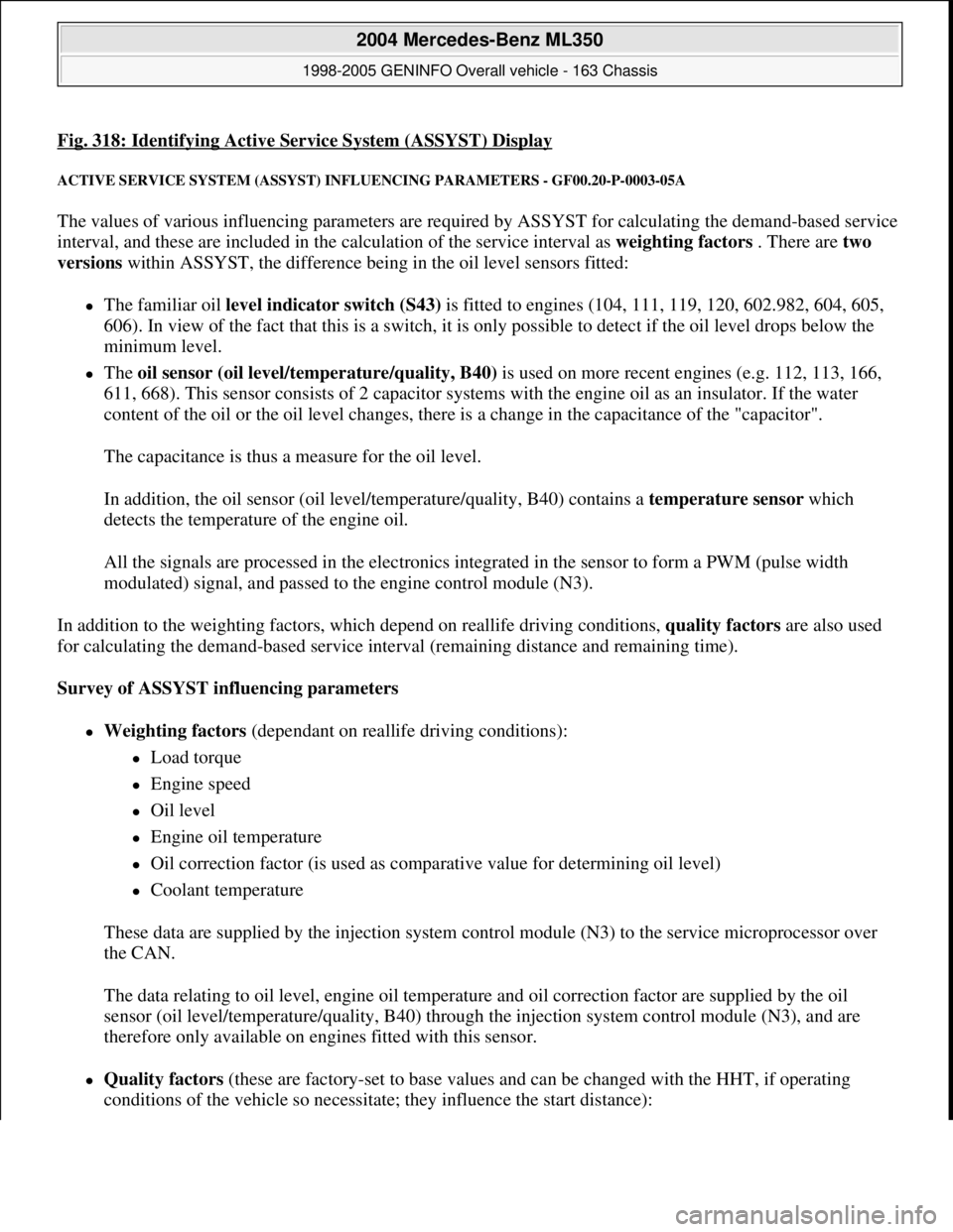
Fig. 318: Identifying Active Service System (ASSYST) Display
ACTIVE SERVICE SYSTEM (ASSYST) INFLUENCING PARAMETERS - GF00.20-P-0003-05A
The values of various influencing parameters are required by ASSYST for calculating the demand-based service
interval, and these are included in the calculation of the service interval as weighting factors . There are two
versions within ASSYST, the difference being in the oil level sensors fitted:
The familiar oil level indicator switch (S43) is fitted to engines (104, 111, 119, 120, 602.982, 604, 605,
606). In view of the fact that this is a switch, it is only possible to detect if the oil level drops below the
minimum level.
The oil sensor (oil level/temperature/quality, B40) is used on more recent engines (e.g. 112, 113, 166,
611, 668). This sensor consists of 2 capacitor systems with the engine oil as an insulator. If the water
content of the oil or the oil level changes, there is a change in the capacitance of the "capacitor".
The capacitance is thus a measure for the oil level.
In addition, the oil sensor (oil level/temperature/quality, B40) contains a temperature sensor which
detects the temperature of the engine oil.
All the signals are processed in the electronics integrated in the sensor to form a PWM (pulse width
modulated) signal, and passed to the engine control module (N3).
In addition to the weighting factors, which depend on reallife driving conditions, quality factors are also used
for calculating the demand-based service interval (remaining distance and remaining time).
Survey of ASSYST influencing parameters
Weighting factors (dependant on reallife driving conditions):
Load torque
Engine speed
Oil level
Engine oil temperature
Oil correction factor (is used as comparative value for determining oil level)
Coolant temperature
These data are supplied by the injection system control module (N3) to the service microprocessor over
the CAN.
The data relating to oil level, engine oil temperature and oil correction factor are supplied by the oil
sensor (oil level/temperature/quality, B40) through the injection system control module (N3), and are
therefore only available on engines fitted with this sensor.
Quality factors (these are factory-set to base values and can be changed with the HHT, if operating
conditions of the vehicle so necessitate; they influence the start distance):
2004 Mercedes-Benz ML350
1998-2005 GENINFO Overall vehicle - 163 Chassis
me
Saturday, October 02, 2010 3:47:47 PMPage 197 © 2006 Mitchell Repair Information Company, LLC.
Page 2849 of 4133
The figure may differ from this, however, depending on quality factors.
The start distance is automatically reset to its initial value by the oil change reset each time the oil is changed.
The start distance is an internal computed quantity and cannot be displayed in the instrument cluster. It is
possible to display the start distance with the HHT.
What is normally displayed in the instrument cluster is the remaining distance .
The remaining distance is the same as the start distance immediately after the oil change. On engines with oil
sensor (e.g. 112, 113, 166, 611, 668) this applies only, however, if the specified quantity of oil has been added
during the oil change.
The remaining distance is the distance which remains from the current kilometer reading until the next
service. The possible length of the interval is at least as great as the remaining distance displayed
immediately after an oil change, and is at the most twice the start distance.
The remaining distance is dependent on
the start distance
the driving conditions (a weighting of the distance driven takes place)
any oil replenishments in the case of engines with oil sensor (e.g. 112, 113, 166, 611, 668)
Consequently, ASSYST also takes into account the driving conditions: In the case of a favorable weighting
(e.g. small number of cold starts, no high engine revs, small number of short-distance trips, minimum extent of
towing a trailer etc.) and oil replenishments, the driver is provided with a bonus which extends the remaining
distance and thus the service interval. Account is also taken of whether the vehicle is actually driven or whether
the engine runs at idle speed. ASSYST is constantly supplied with the data regarding the current operating
conditions of the vehicle for this purpose.
In the case of the best weighting , only 0.6 km are added for each kilometer driven.
In the case of the most unfavorable weighting of the distance (e.g. frequent short-distance trips, large number
of cold starts), the remaining distance and thus the service interval is smaller than in the case of the most
favorable weighting (assuming identical quality factors).
In the case of the most unfavorable weighting, up to 3 km are added for each kilometer driven.
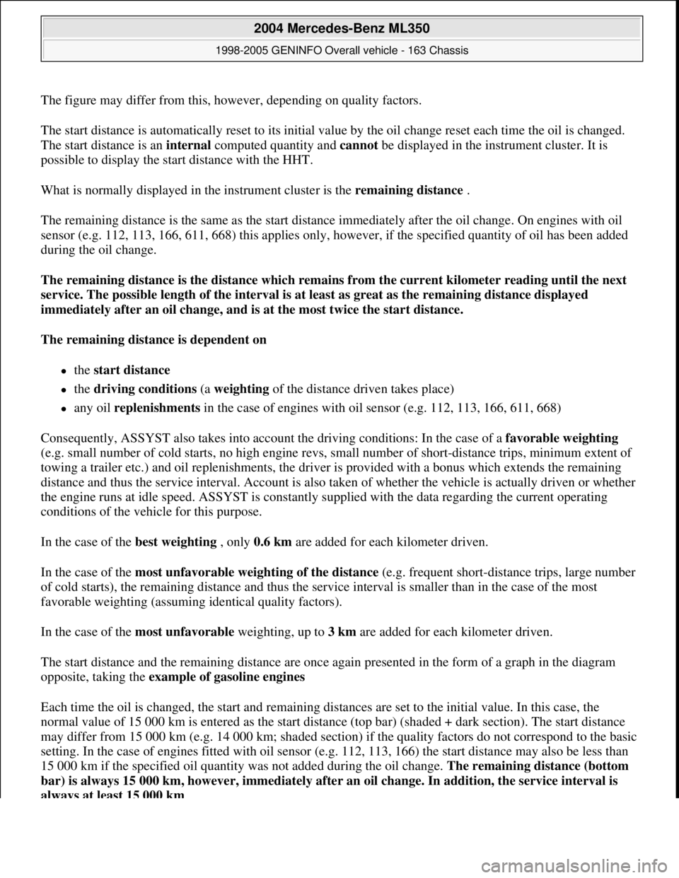
The start distance and the remaining distance are once again presented in the form of a graph in the diagram
opposite, taking the example of gasoline engines
Each time the oil is changed, the start and remaining distances are set to the initial value. In this case, the
normal value of 15 000 km is entered as the start distance (top bar) (shaded + dark section). The start distance
may differ from 15 000 km (e.g. 14 000 km; shaded section) if the quality factors do not correspond to the basic
setting. In the case of engines fitted with oil sensor (e.g. 112, 113, 166) the start distance may also be less than
15 000 km if the specified oil quantity was not added during the oil change. The remaining distance (bottom
bar) is always 15 000 km, however, immediately after an oil change. In addition, the service interval is
always at least 15 000 km .
2004 Mercedes-Benz ML350
1998-2005 GENINFO Overall vehicle - 163 Chassis
me
Saturday, October 02, 2010 3:47:47 PMPage 204 © 2006 Mitchell Repair Information Company, LLC.
Page 2852 of 4133
MODEL 129 as of 1.6.97
MODEL 140 as of 1.6.97
MODEL 163
MODEL 168
MODEL 170 as of 1.6.97
MODEL 202 as of 1.6.97
MODEL 208 up to 31.7.99
MODEL 210 as of 1.3.97 up to 30.6.99
Start time and remaining time
Start time refers to the service interval in days immediately after the oil change
The start time is not dependent on the driving conditions and any oil replenishments .
The start time is 730 days ( 365 days).
The start time is automatically reset to its initial value by the oil change reset after each oil change. The start
time is an internal computed variable and cannotbe displayed in the instrument cluster. It is possible to display
the start time with the HHT.
The remaining time is displayed in the instrument cluster under certain conditions as stated below.
The remaining time is the time which remains until the next service.
The remaining time is only of importance for "low-mileage drivers". (It is therefore the remaining distance
which is displayed as a general rule.)
The remaining time depends on:
the start time
the driving conditions (the distance driven is weighted in this case.)
Replenishing oil, however, does not have any influence on the remaining time.
As a result of these dependent factors, ASSYST proves to be a demand-oriented system even for "low-mileage
drivers". Depending on the weighting of the factors, the service interval for "low-mileage drivers" is between 1
and 2
years.
2004 Mercedes-Benz ML350
1998-2005 GENINFO Overall vehicle - 163 Chassis
me
Saturday, October 02, 2010 3:47:47 PMPage 207 © 2006 Mitchell Repair Information Company, LLC.
Page 2855 of 4133
An excess oil level or insufficient oil level appears in the display together with the oil can symbol.
Display of low oil level at maximum:
at driver request
Display of warnings:
automatically, at the earliest 60s after engine start and oil temperature greater than 60°C:
if oil level too high: the oil can symbol appears together with the readout "OIL LEVEL ABOVE
MAX". In addition, a brief warning signal sounds. (On models not fitted with multifunction
display, "HI" appears flashing.)
if oil level too low: the oil can symbol appears together with the readout "OIL LEVEL BELOW
MIN". In addition, a brief warning signal sounds. (On models not fitted with multifunction display,
the oil level warning lamp (A1e12) comes on and the readout "-2L" appears flashing.)
if oil at minimum: the oil can symbol appears together with the readout "OIL LEVEL MINIMUM".
In addition, a brief warning signal sounds. (On models not fitted with multifunction display, the oil
level warning lamp (A1e12) comes on.)
automatically 13 s after ignition ON:
if no oil is in engine: the oil can symbol appears together with the readout "OIL LEVEL BELOW
MIN". In addition, a warning signal sounds. (On models not fitted with multifunction display, the
oil level warning lamp (A1e12) comes on and the readout "-2L" appears flashing. In addition a
brief warning signal sounds.)
The missing oil quantity displayed no longer changes during the display. In other words, any change in oil level
cannot be observed directly at the display. The new oil level is only displayed once the conditions described
below exist.
Display of oil quantity at driver request
The text "DISPLAY OIL LEVEL?" appears 10 s after the start switch has been turned into position "2" (on
models not fitted with multifunction display, the oil can and the clock symbol are displayed).
If the reset button of the trip counter is pressed twice within one sec. during this readout, for example, "add 1.0L
oil" (or "-1.0L")
appears in the display if oil level too low. The readout appears only after the elapse of a waiting time after
engine OFF. The waiting time depends on the engine oil temperature.
It is
up to 20°C 30 minutes
from 60°C 1 minute
The waiting time is between these two limits at other engine oil temperatures.
2004 Mercedes-Benz ML350
1998-2005 GENINFO Overall vehicle - 163 Chassis
me
Saturday, October 02, 2010 3:47:47 PMPage 210 © 2006 Mitchell Repair Information Company, LLC.
Page 2856 of 4133
Possible readouts are (text in parenthesis relates to models not fitted with multifunction display.):
"OIL LEVEL OKAY" ("o.k."),
1.0L, 1.5L, 2L,
"Overfilling" ("HI"),
"OBSERVE WAITING TIME" (clock symbol flashing and oil can symbol),
"DISPLAY OIL LEVEL" (clock and oil can symbols.)
If there is a fault at the oil sensor (oil level/temperature/quality, B40) the oil can symbol and the text "OIL
LEVEL SENSOR FAULTY" appears only 30 s after the fault has occurred.
(On models not fitted with multifunction display, the oil level warning lamp (A1e12) comes on accordingly.)
For diagnosis, read also the injection system control module (N3) with the HHT. (The instrument cluster (A1)
receives the sensor data through the CAN from the injection system control module (N3)).
Oil change
The ASSYST has to be reset each time the oil is changed. Resetting ASSYST also resets the remaining time and
the remaining distance. Resetting can be performed at the instrument cluster or using the HHT. The following
data are stored when the system is reset:
current kilometer reading rounded off to 100,
total oil replenishments in the last interval,
remaining distance,
remaining time,
product of the quality factors,
the data of the last 5 resettings in 5 data sets
These data can only be read with the HHT!
If the specified quantity of oil is not replenished when the oil is changed, the (internal) start distance is
reduced.
Detecting oil replenishments
With the HHT it is possible to retrieve the last 10 oil replenishments and the corresponding kilometer
readings of the current interval.
In the normal case, detection of an oil replenishment is displayed by the remaining distance in the
instrument cluster being extended
Oil replenishments are always only detected once the following conditions are met:
the replenished quantit
y is at least
2004 Mercedes-Benz ML350
1998-2005 GENINFO Overall vehicle - 163 Chassis
me
Saturday, October 02, 2010 3:47:47 PMPage 211 © 2006 Mitchell Repair Information Company, LLC.
Page 2858 of 4133
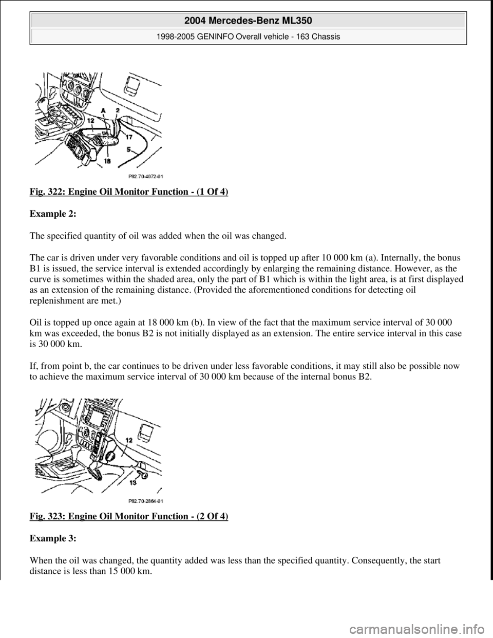
Fig. 322: Engine Oil Monitor Function - (1 Of 4)
Example 2:
The specified quantity of oil was added when the oil was changed.
The car is driven under very favorable conditions and oil is topped up after 10 000 km (a). Internally, the bonus
B1 is issued, the service interval is extended accordi ngly by enlarging the remaining distance. However, as the
curve is sometimes within the shaded ar ea, only the part of B1 which is within the light area, is at first displayed
as an extension of the remaining distance. (Provi ded the aforementioned conditions for detecting oil
replenishment are met.)
Oil is topped up once again at 18 000 km (b ). In view of the fact that the maximum service interval of 30 000
km was exceeded, the bonus B2 is not initially displayed as an extension. Th e entire service interval in this case
is 30 000 km.
If, from point b, the car continues to be driven under less favorable conditions , it may still also be possible now
to achieve the maximum service interval of 30 000 km because of the internal bonus B2.
Fig. 323: Engine Oil Monitor Function
- (2 Of 4)
Example 3:
When the oil was changed, the quantity added was less than the specified quantity. Consequently, the start
distance is less than 15 000 km.
2004 Mercedes-Benz ML350
1998-2005 GENINFO Overall vehicle - 163 Chassis
me
Saturday, October 02, 2010 3:47:47 PMPage 213 © 2006 Mitchell Repair Information Company, LLC.