1997 MERCEDES-BENZ ML350 change time
[x] Cancel search: change timePage 1678 of 4133
Parts ordering notes
AUDIO SYSTEM FAILS TO MUTE WHEN INCOMING PHONE CALLS RECEIVED - AF82.85-P-6010A
MODEL 163.113 /154 /172 /174 #A as of 221506 up to 289564, 163.113 #X as of 734088 up to 754619 with
CODE (352a) COMAND operating and display system with CODE (353) Audio 30 APS with CODE
(756b) MB Audio 10 CD radio with TP/RDS with CODE (819a) CD changer with CODE (854) MB
portable cellular telephone
Modification notes
A 203 820 91 89
A 208 820 40 89
A 210 820 54 89
A 220 820 37 89
A 463 820 10 89
CD covers exist with
incorrect part number for
model series 203.
Do not update part
number
A 203 820 96 89.
The CD should remain
in the workshop (service
CD)
It can be used several
times and should not be
given to customers!
Always order service CD
in advance to avoid
longer workshop visits!
Part no.DesignationQuantity
W 215 589 00 22 00COMAND service update CD1
17.9.01Supersedes STI no.
82.85-024 dated 14.9.01
Damage codeCauseRemedy
Software error in CD
changer.1 Inspect CD changer
part number
On vehicles equipped
with Code 352a, 756b or
353 in combination with
Code 819a and 854 the
audio system may
sporadically fail to auto-
mute when incoming If equipped with part
number: 163 820 15 89 ,
then ?
2001 Mercedes-Benz ML320
1998-2005 ACCESSORIES & BODY, CAB Electrical System - Body - 163 Chassis
me
Saturday, October 02, 2010 3:30:07 PMPage 183 © 2006 Mitchell Repair Information Company, LLC.
Page 1679 of 4133
Parts ordering notes
NAVIGATION SYSTEM ERRONEOUS OR NO GUIDANCE - AF82.85-P-6061A
MODEL 163, 168, 170, 203, 208, 209, 210, 211, 215, 220, 230, 414, 463
phone calls are received.
2 Replace CD changer
See parts ordering
notes.AR82.64-P-7507GH
Part no.DesignationQuantity
163 820 38 89CD changer1
Damage codeCauseRemedy
Defective digitization of
map material1 Perform test drive with
other vehicle
Possible switch-off or
falsification of GPS
signals during worldwide
crisis This must be
compared with the same
navigation system and the
same version of
navigation CD.
The satellite signal
includes the time at
which the signal was sentIf the complaint is still
present: ?
The navigation processor
Calculate the
transmission time of the
signal resulting from the
satellite position and the
transmission time of the
GPS signal and can
therefore determine the
vehicle position (min. 3
satellites).2 Perform test drive with
new navigation CD
version.
If the GPS signal is
falsified the transmitted
time from the satellites is
changed. A change of 10
ns corresponds to approx.
3 m position changeWhen the complaint is
eliminated, use new
navigation CD.
If the complaint is still
present: ?
3 Perform test drive with
other vehicle and
navigation system of
2001 Mercedes-Benz ML320
1998-2005 ACCESSORIES & BODY, CAB Electrical System - Body - 163 Chassis
me
Saturday, October 02, 2010 3:30:07 PMPage 184 © 2006 Mitchell Repair Information Company, LLC.
Page 1680 of 4133
MCS MALFUNCTION - OCCASIONAL FAILURE OF STARGUIDE, SOUND OR CD CHANGER. DTC'S N1111, N1112, N1116
- AF82.95-P-6002A
MODEL 163.157 /174 /175 #A as of 409851 up to 419036 with CODE (349) E Call emergency call system
with CODE (522) Modular control system (MCS) radio USA
Operation no. of operation texts or standard texts and flat rates
other manufacturer.
If the complaint does
not occur during the test
drive, a digitization error
on the navigation CD is
present: ?
4 Inform customers of
facts and manufacturer of
CD with report form
If the correct report
form from the
manufacturer is not
available, please contact
corresponding service
center (telephone number
is given on label of
navigation CD):
5 Check antenna system
for proper function and
repair according to
condition.
If the antenna system
is okay and errors also
occur on other vehicles: ?
6 Inform customer that
the GPS system is
operated by the US
military
RangeOp. no.Operation textTimeAcc. no.Code
P023843FLASH TELEAID
EMERGENCY CALL
SYSTEM CONTROL
MODULE008 WU/0.7 h82 876 90-
Damage codeCauseRemedy
Data transmission of D2B
ring is interrupted. The E-
call control module is in a Recode E-call control
module: ?
2001 Mercedes-Benz ML320
1998-2005 ACCESSORIES & BODY, CAB Electrical System - Body - 163 Chassis
me
Saturday, October 02, 2010 3:30:07 PMPage 185 © 2006 Mitchell Repair Information Company, LLC.
Page 1740 of 4133
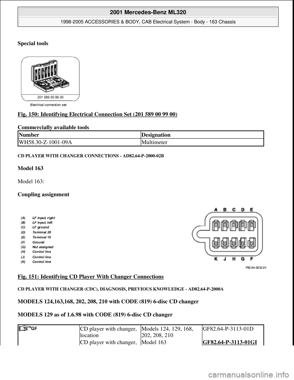
Special tools
Fig. 150: Identifying Electrical Connection Set (201 589 00 99 00)
Commercially available tools
CD PLAYER WITH CHANGER CONNECTIONS - AD82.64-P-2000-02B
Model 163
Model 163:
Coupling assignment
Fig. 151: Identifying CD Player With Changer Connections
CD PLAYER WITH CHANGER (CDC), DIAGNOSIS, PREVIOUS KNOWLEDGE - AD82.64-P-2000A
MODELS 124,163,168, 202, 208, 210 with CODE (819) 6-disc CD changer
MODELS 129 as of 1.6.98 with CODE (819) 6-disc CD changer
NumberDesignation
WH58.30-Z-1001-09AMultimeter
CD player with changer,
locationModels 124, 129, 168,
202, 208, 210GF82.64-P-3113-01D
CD player with changer, Model 163GF82.64-P-3113-01GI
2001 Mercedes-Benz ML320
1998-2005 ACCESSORIES & BODY, CAB Electrical System - Body - 163 Chassis
me
Saturday, October 02, 2010 3:30:08 PMPage 245 © 2006 Mitchell Repair Information Company, LLC.
Page 1830 of 4133
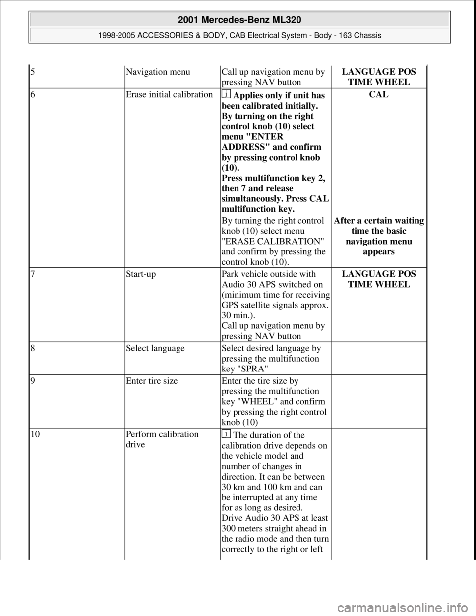
5Navigation menuCall up navigation menu by
pressing NAV buttonLANGUAGE POS
TIME WHEEL
6Erase initial calibration Applies only if unit has
been calibrated initially.
By turning on the right
control knob (10) select
menu "ENTER
ADDRESS" and confirm
by pressing control knob
(10).
Press multifunction key 2,
then 7 and release
simultaneousl
y. Press CAL
multifunction key.
CAL
By turning the right control
knob (10) select menu
"ERASE CALIBRATION"
and confirm by pressing the
control knob (10).After a certain waiting
time the basic
navigation menu
appears
7Start-upPark vehicle outside with
Audio 30 APS switched on
(minimum time for receiving
GPS satellite signals approx.
30 min.).
Call up navigation menu by
pressing NAV buttonLANGUAGE POS
TIME WHEEL
8Select languageSelect desired language by
pressing the multifunction
key "SPRA"
9Enter tire sizeEnter the tire size by
pressing the multifunction
key "WHEEL" and confirm
by pressing the right control
knob (10)
10Perform calibration
drive The duration of the
calibration drive depends on
the vehicle model and
number of changes in
direction. It can be between
30 km and 100 km and can
be interrupted at any time
for as long as desired.
Drive Audio 30 APS at least
300 meters straight ahead in
the radio mode and then turn
correctly to the right or left
2001 Mercedes-Benz ML320
1998-2005 ACCESSORIES & BODY, CAB Electrical System - Body - 163 Chassis
me
Saturday, October 02, 2010 3:30:11 PMPage 335 © 2006 Mitchell Repair Information Company, LLC.
Page 1905 of 4133
RETROFITTING TRAFFICSTAR NAVIGATION SYSTEM - AZ82.61-P-0001I
MODEL 163 up to 30.6.99 except CODE (819) 6-disk CD changer in trunk
System illustration
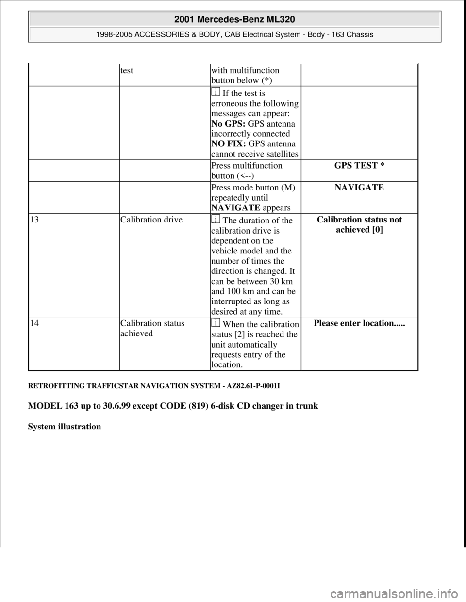
testwith multifunction
button below (*)
If the test is
erroneous the following
messages can appear:
No GPS: GPS antenna
incorrectly connected
NO FIX: GPS antenna
cannot receive satellites
Press multifunction
button (<--)GPS TEST *
Press mode button (M)
repeatedly until
NAVIGATE appearsNAVIGATE
13Calibration drive The duration of the
calibration drive is
dependent on the
vehicle model and the
number of times the
direction is changed. It
can be between 30 km
and 100 km and can be
interrupted as long as
desired at any time.Calibration status not
achieved [0]
14Calibration status
achievedWhen the calibration
status [2] is reached the
unit automatically
requests entry of the
location.Please enter location.....
2001 Mercedes-Benz ML320
1998-2005 ACCESSORIES & BODY, CAB Electrical System - Body - 163 Chassis
me
Saturday, October 02, 2010 3:30:13 PMPage 410 © 2006 Mitchell Repair Information Company, LLC.
Page 2236 of 4133

GF00.20-P-2009A
Engine oil monitor function
24.10.96
MODEL
129 with ENGINE 112, 113
MODEL
163 with ENGINE 112, 113, 612
MODEL
168 with ENGINE 166, 668
MODEL
202 with ENGINE 112, 611
MODEL
208 up to 31.7.99 with ENGINE 112, 113
MODEL
210 up to 30.6.99 with ENGINE 112, 113, 611
General
The oil level is constantly monitored by the oil sensor, and the
appropriate data transmitted to the processor by the ASSYST.
Oil replenishments are detected automatically and result in a bonus,
which extends the service interval accordingly.
An excess oil level or insufficient oil level appears in the display
together with the oil can symbol.
Display of low oil level at maximum:
D
at driver request
Display of warnings: D
automatically, at the earliest 60 s after engine start and oil
temperature greater than 60°C:
D
if oil level too high: the oil can symbol appears together
with the readout "OIL LEVEL ABOVE MAX". In addition, a
brief warning signal sounds. (On models not fitted with
multifunction displaly, "HI" appears flashing.)
D
if oil level too low: the oil can symbol appears together with
the readout "OIL LEVEL BELOW MIN". In addition, a brief
warning signal sounds. (On models not fitted with multifunction
display, the oil level warning lamp (A1e12) comes on and the
readout "-2L" appears flashing.)
-----------------------------------------------------------------------------------------
D
if oil at minimum: the oil can symbol appears together with
the readout "OIL LEVEL MINIMUM". In addition, a brief
warning signal sounds. (On models not fitted with multifunction
display, the oil level warning lamp (A1e12) comes on.)
D
automatically 13 s after ignition ON:
D
if
no oil
is in engine: the oil can symbol appears together
with the readout "OIL LEVEL BELOW MIN". In addition, a
warning signal sounds. (On models not fitted with multifunction
display, the oil level warning lamp (A1e12) comes on and the
readout "-2L"appears flashing. In addition a brief warning
signal sounds.)
The missing oil quantity displayed no longer changes during the
display. In other words, any change in oil level cannot be observed
directly at the display. The new oil level is only displayed once the
conditions described below exist.
Display of oil quantity at driver request
The text "DISPLAY OIL LEVEL?" appears 10 s after the start switch
has been turned into position "2" (on models not fitted with
multifunction display, the oil can and the clock symbol are displayed).
If the reset button of the trip counter is pressed twice within one sec.
during this readout, for example, "add 1.0L oil" (or "-1.0L")
-----------------------------------------------------------------------------------------
appears in the display if oil level too low. The readout appears only
after the elapse of a waiting time after engine OFF. The waiting time
depends on the engine oil temperature.
It is
D
up to 20°C
30 minutes
D
from 60°C
1 minute
D
The waiting time is between these two limits at other engine oil
temperatures.
Possible readouts are (text in parenthesis relates to models not fitted
with multifunction display.):
D
"OIL LEVEL OKAY" ("o.k."),
D
1.0L, 1.5L, 2L,
D
"Overfilling" ("HI"),
D
"OBSERVE WAITING TIME" (clock symbol flashing and oil can
symbol),
D
"DISPLAY OIL LEVEL" (clock and oil can symbols.)
If there is a fault at the oil sensor (oil level/temperature/quality, B40)
the oil can symbol and the text "OIL LEVEL SENSOR FAULTY"
appears only 30 s after the fault has occurred.
(On models not fitted with multifunction display, the oil level warning
lamp (A1e12) comes on accordingly.)
For diagnosis, read also the injection system control module (N3)
with the HHT. (The instrument cluster (A1) receives the sensor data
through the CAN from the injection system control module (N3)).
-----------------------------------------------------------------------------------------
Oil change
The ASSYST has to be reset each time the oil is changed. Resetting
ASSYST also resets the remaining time and the remaining distance.
Resetting can be performed at the instrument cluster or using the
HHT.
The following data are stored when the system is reset:
D
current kilometer reading rounded off to 100,
D
total oil replenishments in the last interval,
D
remaining distance,
D
remaining time,
D
product of the quality factors,
D
the data of the last 5 resettings in 5 data sets
These data can only be read with the HHT!
If the specified quantity of oil is not replenished when the oil is
changed, the (internal) start distance is reduced.
Detecting oil replenishments
D
With the
HHT
it is possible to retrieve the last 10 oil
replenishments and the corresponding kilometer readings of
the current interval.
D
In the normal case, detection of an oil replenishment is
displayed by the remaining distance in the instrument cluster
being extended
-----------------------------------------------------------------------------------------
Copyright DaimlerChrysler AG 05.06.2006 CD-Ausgabe G/10/04 . This WIS print-out will not be recorde
d by Modification services.
Page 1
Page 2237 of 4133
Oil replenishments are always only detected once the following
conditions are met:
D
the replenished quantity is
at least 1 l
D
after replenishing the oil, the car must be driven a distance of
at
least 5 km
under
normal driving conditions
at an
oil
temperature of at least 60 °C
.
There are instances, however, in which the readout of the remaining
distance nevertheless appears implausible after replenishing oil;
according to the display, no bonus or only a small bonus has been
issued. This is caused by the fact that the remaining distance is
always only displayed within a range from 15 000 km up to 30 000
km (or 20 000 km up to 40 000 km in the case of engine 668), but
internally the system calculates with the actual values which may also
be beyond this range. These internal values can only be displayed
with the HHT.
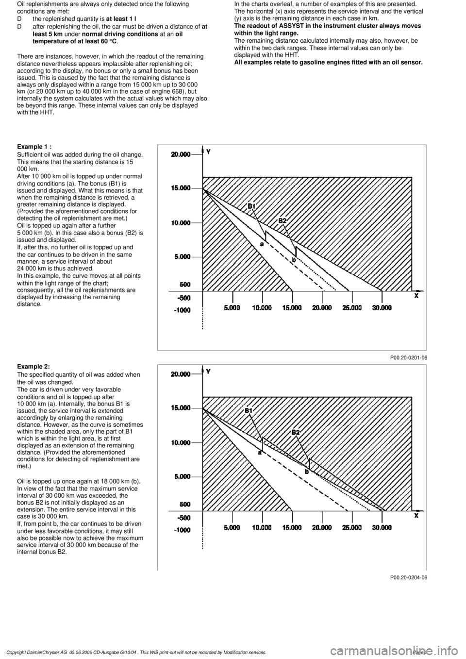
In the charts overleaf, a number of examples of this are presented.
The horizontal (x) axis represents the service interval and the vertical
(y) axis is the remaining distance in each case in km.
The readout of ASSYST in the instrument cluster always moves
within the light range.
The remaining distance calculated internally may also, however, be
within the two dark ranges. These internal values can only be
displayed with the HHT.
All examples relate to gasoline engines fitted with an oil sensor.
P00.20-0201-06
Example 1 :
Sufficient oil was added during the oil change.
This means that the starting distance is 15
000 km.
After 10 000 km oil is topped up under normal
driving conditions (a). The bonus (B1) is
issued and displayed. What this means is that
when the remaining distance is retrieved, a
greater remaining distance is displayed.
(Provided the aforementioned conditions for
detecting the oil replenishment are met.)
Oil is topped up again after a further
5 000 km (b). In this case also a bonus (B2) is
issued and displayed.
If, after this, no further oil is topped up and
the car continues to be driven in the same
manner, a service interval of about
24 000 km is thus achieved.
In this example, the curve moves at all points
within the light range of the chart;
consequently, all the oil replenishments are
displayed by increasing the remaining
distance.
P00.20-0204-06
Example 2:
The specified quantity of oil was added when
the oil was changed.
The car is driven under very favorable
conditions and oil is topped up after
10 000 km (a). Internally, the bonus B1 is
issued, the service interval is extended
accordingly by enlarging the remaining
distance. However, as the curve is sometimes
within the shaded area, only the part of B1
which is within the light area, is at first
displayed as an extension of the remaining
distance. (Provided the aforementioned
conditions for detecting oil replenishment are
met.)
Oil is topped up once again at 18 000 km (b).
In view of the fact that the maximum service
interval of 30 000 km was exceeded, the
bonus B2 is not initially displayed as an
extension. The entire service interval in this
case is 30 000 km.
If, from point b, the car continues to be driven
under less favorable conditions, it may still
also be possible now to achieve the maximum
service interval of 30 000 km because of the
internal bonus B2.
Copyright DaimlerChrysler AG 05.06.2006 CD-Ausgabe G/10/04 . This WIS print-out will not be recorde
d by Modification services.
Page 2