1997 MERCEDES-BENZ ML350 change time
[x] Cancel search: change timePage 3835 of 4133

SI18.00-P-0010A
Service Information: oil sludge
26.3.01
ENGINE
111 in MODELS 124, 163, 170, 202, 203, 208, 210
ENGINE
112 in MODELS 129, 163, 170, 202, 203, 208, 210, 220
ENGINE
112, 113 in MODEL 463
ENGINE
113 in MODELS 129, 163, 202, 208, 210, 215, 220
ENGINE
137 in MODEL 215, 220
ENGINE
166 in MODEL 168
Oil sludging in gasoline engines with ASSYST maintenance
system
Recently we have determined that time and time again oil
sludging occurs in gasoline engines with an ASSYST maintenance
system.
Oil sludging can lead to the following complaints:
D
engine oil consumption
D
engine smoke (white/blue)
D
influencing of oil level indicator
D
clogged oil filter, engine oil thickened like jelly
D
Check engine lamp illuminated
D
oil sludge visible during assembly job, e.g. in oil filter, in cylinder
head covers, condensation sludging
(engine 166) etc.
-----------------------------------------------------------------------------------------
The following list of causes may lead individually or as a combination
to engine oil sludging:
D
Crankcase ventilation inoperable, function orifices, bores,
passages in cylinder head cover, cylinder head, crankcase etc.
are mechanically sealed. A nonfunctioning crankcase
ventilation boosts loads on the engine oil through organic
nitrates. The risk of oil sludging increases.
The mechanical condition of the engine is always to be
checked, i.e. all engine oil drain orifices on the cylinder head
and crankcase and all crankcase ventilation ducts must be free
of obstacles. Crankcase breather lines may not be kinked.
Check the ventilation bores in the cylinder head covers.
-----------------------------------------------------------------------------------------
D
The engine oil used does not comply with the specifications in
Sheet 229.1 or 229.3 of the Specifications for Service Products.
The additive process, e.g. dirt-carrying capability, neutralization
capability and oxidation resistance as well as the quality of the
base stock influence sludging time.
Use of engine oils with best possible resistance to formation of
sludge, i.e. use only tested and approved engine oils (from
Sheet 229.1 or 229.3). The best protection is afforded by the
engine oils on Sheet 229.3, which fulfill more stringent
specifications with regard to preventing sludge and deposits
(see Sheet 221.0, page 11). These oils have a distinctly better
anti-sludge characteristic than other engine oils.
D
Sludging after adding a fuel or engine oil special additive.
Do not use fuel or engine oil special additives. More information
hereto is available on Sheet 219.0 of the Specifications for
Service products. Reference to customer not to use special
additives.
D
Engine oil change not performed according to ASSYST
specifications. At driven distances
exceeding > approx. 3000 km, engine oil sludging may occur.
-----------------------------------------------------------------------------------------
Comply with engine oil and filter change as under ASSYST
specifications. Observe remaining distance.
D
Fuel grade lies outside standard (regionally contingent). If
contaminated, deficient fuel is used, then engine oil sludging
may occur even where approved engine oil is used.
Operation with fuel, e.g. as under DIN EN 228. Clarify refueling
behavior of customer. If engine operation regional, is
temporarily possible with deficient oil only, then the startup
distance has to be individually reduced, i.e. the oil change
temporarily performed at an interval of, e.g. 10,000 km.
D
Radiator antifreeze penetration into engine oil, e.g. through an
internal engine leak (cylinder head gasket, casting porosity).
The engine oil sludges within a short period. The crankcase
ventilation clogs up and stops functioning. Condensation
sludging clogs up the oil separator cells
(engine 166).
Rectify coolant leakage. Clean all sludged engine parts, in
particular the crankcase ventilation parts. If the occurrence
repeats, and casting porosity is suspected, e.g. replace
crankcase.
-----------------------------------------------------------------------------------------
Copyright DaimlerChrysler AG 20.05.2006 CD-Ausgabe G/10/04 . This WIS print-out will not be recorde
d by Modification services.
Page 1
Page 3901 of 4133

GF54.30-P-3009A
Stepper motor, location/design/function
7.7.99
MODEL
129, 140 as of 1.6.96,
163, 168, 170,
202 as of 1.8.96,
208,
210 as of 1.6.96,
215, 220
P54.30-0521-06
General
Stepper motors are motors which, like most
electric motors, consist of a fixed stator and a
moveable rotor. The rotary motion is not
continuous, rather the rotor turns in steps, a
certain angle at a time, for example 90°.
Design
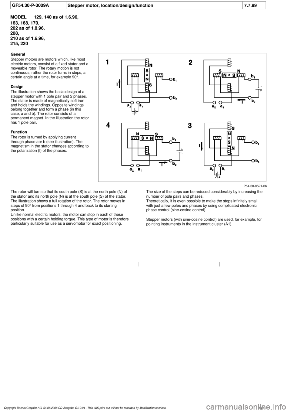
The illustration shows the basic design of a
stepper motor with 1 pole pair and 2 phases.
The stator is made of magnetically soft iron
and holds the windings. Opposite windings
belong together and form a phase (in this
case, a and b). The rotor consists of a
permanent magnet. In the illustration the rotor
has 1 pole pair.
Function
The rotor is turned by applying current
through phase aor b (see illustration). The
magnetism in the stator changes according to
the polarization (I) of the phases.
The rotor will turn so that its south pole (S) is at the north pole (N) of
the stator and its north pole (N) is at the south pole (S) of the stator.
The illustration shows a full rotation of the rotor. The rotor moves in
steps of 90° from positions 1 through 4 and back to its starting
position.
Unlike normal electric motors, the motor can stop in each of these
positions with a certain holding torque. This type of motor is therefore
particularly suitable for use as a servomotor for exact positioning.
The size of the steps can be reduced considerably by increasing the
number of pole pairs and phases.
Theoretically, it is even possible to make the steps infinitely small
with just a few poles and phases by using complicated electronic
phase control (sine-cosine control).
Stepper motors (with sine-cosine control) are used, for example, for
pointing instruments in the instrument cluster (A1).
Copyright DaimlerChrysler AG 04.06.2006 CD-Ausgabe G/10/04 . This WIS print-out will not be recorde
d by Modification services.
Page 1
Page 3962 of 4133

Integrated V60 Digital Cellular Phone
In-Vehicle Operation Guide
Mercedes-Benz
Mercedes-Benz USA, LLC
One Mercedes Drive
Montvale, New Jersey 07645
© 2001 Mercedes-Benz USA, LLC
Technical Information
Order Number S-2790-02A
Printed in the USA
All illustrations and specifications contained in this folder
are based on the latest product information available at the
time of publication approval.
Mercedes-Benz reserves the right to make changes at any
time, without notice.6809437A95-O
10/01-RGC
Page 3966 of 4133

3
Features
This telephone system is fully integrated with your Mercedes-Benz audio system and steering wheel switches
*
. You can
scroll through the first 99 entries in your phone book and access the entire phone number memory; place, receive, and
terminate calls; change volume; and view call status (such as Ready, Dialing, Incoming Call, Call Active, No Service, Redial,
etc.). Because exact phone features are dependent on the particular audio system installed in your vehicle, detailed oper-
ation is covered in your audio system manual. Please refer to it.
Notes:
• In order for your Mercedes-Benz volume controls to work in conjunction with your Motorola phone (to change ringer
volume or adjust call volume), the vehicle must have either the engine running or the ignition key turned clockwise
to the last position before starting the engine.
• Your phone includes many new features that take additional time to initialize, resulting in increased power up/down
time. Please wait until the phone is completely powered up before using any feature from both the radio and phone
controls.
Finding Information on Phone Features
Your new Mercedes-Benz telephone operates in two modes:
•
Vehicular Mode
—when the phone is inserted and snapped into the privacy cradle in the vehicle
•
Portable Mode
—when the phone is operating as a stand alone device (NOT inserted and snapped into the privacy
cradle in the vehicle)
Most features of your new Mercedes-Benz telephone are available in both modes.
This guide contains basic information on using your phone in Vehicular Mode to place and receive calls.
* Not available on all models.
Page 3978 of 4133

Integrated V60 Digital Cellular Phone
In-Vehicle Operation Guide
Mercedes-Benz
Mercedes-Benz USA, LLC
One Mercedes Drive
Montvale, New Jersey 07645
© 2001 Mercedes-Benz USA, LLC
Technical Information
Order Number S-2790-02A
Printed in the USA
All illustrations and specifications contained in this folder
are based on the latest product information available at the
time of publication approval.
Mercedes-Benz reserves the right to make changes at any
time, without notice.6809437A95-O
10/01-RGC