1997 MERCEDES-BENZ ML350 sensor
[x] Cancel search: sensorPage 2238 of 4133
P00.20-0202-06
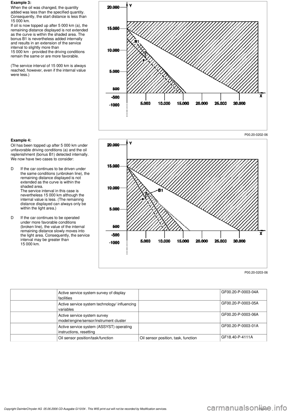
Example 3:
When the oil was changed, the quantity
added was less than the specified quantity.
Consequently, the start distance is less than
15 000 km.
If oil is now topped up after 5 000 km (a), the
remaining distance displayed is not extended
as the curve is within the shaded area. The
bonus B1 is nevertheless added internally
and results in an extension of the service
interval to slightly more than
15 000 km - provided the driving conditions
remain the same or are more favorable.
(The service interval of 15 000 km is always
reached, however, even if the internal value
were less.)
P00.20-0203-06
Example 4:
Oil has been topped up after 5 000 km under
unfavorable driving conditions (a) and the oil
replenishment (bonus B1) detected internally.
We now have two cases to consider:
D
If the car continues to be driven under
the same conditions (unbroken line), the
remaining distance displayed is not
extended as the curve is within the
shaded area.
The service interval in this case is
nevertheless 15 000 km although the
internal value is less. (The remaining
distance displayed can always only be
within the light area.)
D
If the car continues to be operated
under more favorable conditions
(broken line), the value of the internal
remaining distance slowly moves into
the light area. Consequently, the service
interval may be greater than
15 000 km.
Active service system survey of display
facilities
GF00.20-P-0003-04A
Active service system technology/ influencing
variables
GF00.20-P-0003-05A
Active service system survey
model/engine/sensor/instrument cluster
GF00.20-P-0003-06A
Active service system (ASSYST) operating
instructions, resetting
GF00.20-P-0003-01A
Oil sensor position/task/function
Oil sensor position, task, function
GF18.40-P-4111A
Copyright DaimlerChrysler AG 05.06.2006 CD-Ausgabe G/10/04 . This WIS print-out will not be recorde
d by Modification services.
Page 3
Page 2239 of 4133

AF07.00-P-9000B
Engine runs rough, surges or does not turn over
29.4.02
ENGINE
611 in MODEL 203, 202, 210
ENGINE
612 in MODEL 163, 203, 210, 209
ENGINE
613 in MODEL 210, 220
ENGINE
628 in MODEL 163, 220, 211
ENGINE
646 in MODEL 203, 211
ENGINE
647 in MODEL 211
ENGINE
648 in MODEL 220, 211
ENGINE
668 in MODEL 168
ENGINE
612, 628 in MODEL 463
Modification notes
23.3.01
Supersedes STIP 07.16-014 dated 11.12.00
Damage code
Cause
Remedy
07 206 D5
High-pressure pump
To verify whether high pressure pump is
damaged.
#
High pressure pump of common rail
injection system is damaged mechanically.
1
Remove/install/replace high pressure
pump.
When the high pressure pump of the common
rail injection system is damaged metal chips
and/or damage to the pump drive (timing
drive) can occur due to contamination of the
injection system components.
2
Turn high pressure pump by hand with
driver.
If mechanical resistance can be felt,
perform the following tests. Clarify additional
work with ESKULAB by specifying repair work:
#
3
Check driver of high pressure pump or
mount in sprocket for damage (visual
check).
If high pressure pump is locked:
#
4
Check timing
5
Check timing drive for damage.
In each case:
#
6
Remove/install/replace timing chain.
If timing deviates by a crankshaft angle of
more than 20 degrees (corresponding to one
tooth skipped):
#
7
Check pressure loss.
8
Open low pressure connection on high
pressure pump return (plastic line in
area of pressure regulator valve) and
check connection point in rail for chips.
If chips are present when checking
injection system:
#
9
Thoroughly clean all fuel low pressure
lines as well as feed and return lines.
Flush and blow out with compressed air.
10
Remove fuel preheater and fuel filter
with filter housing, replace.
Fuel preheater is only installed in models
202, 203 and 163.
11
Remove/install/replace fuel cooler at
vehicle and engine end.
Not installed in model 210 up to 6/99 and
model 168.
12
Remove fuel tank, replace.
On engine 628:
#
13
Remove/install/replace electric supply
pump.
14
Remove/install/replace injectors, rail
(including pressure regulation valve and
rail pressure sensor), high pressure
lines and injector leak oil rail.*
Copyright DaimlerChrysler AG 28.05.2006 CD-Ausgabe G/10/04 . This WIS print-out will not be recorde
d by Modification services.
Page 1
Page 2271 of 4133
camshafts
The copper plates of the
timing chain must be
aligned with the scribe
marks on the camshaft
sprockets.
Owing to the unevenly long
paths of the timing chain it
may be necessary to crank
the engine as many as 14
times till the copper plates
get aligned with the scribe
marks on the camshaft
sprockets.
On vehicles equipped
with an air pump, the
combination valve must be
unbolted before the right
locking plate is inserted.
Installation: Replace
combination valve gasket.
*BA09.20-P-1001-01D
Locating plateFig. 11
Locating plateFig. 12
Timing chain drive -
generalEngines 112, 113GF05.10-P-9611-01C
6Remove chain tensionerModels 163.174, 215, 220
Models 170, 202, 203,
208.365/465
Models 209, 210,
211061/065/070
Model 230.474 with engine
113.992AR05.10-P-7800CA
7Remove camshaft
position sensor AR15.10-P-2000A
8Crank engine in direction
of rotation until the link
for separating the timing
chain is easily accessible The separation point for
the timing chain is one link
down from the copper tab
(right).
See new timing chain.
9Remove camsha ft bearing
bridge on rightEngine 112, 113AR05.20-P-7103AU
Engine 113.960 with code
(479) Cylinder shutoffAR05.20-P-7103AV
10Install holding bush (3)
onto camshaft on right Only insert bolts (4)
until they make contact. Fig. 40
2004 Mercedes-Benz ML350
1998-2005 ENGINE Engine timing - 163 Chassis
me
Saturday, October 02, 2010 3:39:37 PMPage 30 © 2006 Mitchell Repair Information Company, LLC.
Page 2272 of 4133
Holding bush
11Bolt on holding devices
(1, 2) for timing chain at
right and left cylinder
heads RetainerFig. 39
12Disconnect timing chain Cover over timing case
recess with a clean cloth.
Parts which have dropped
into the timing case recess,
must be removed.
To pull out the old
timing chain, connect the
old chain to the new timing
chain.AR05.10-P-7601-01AV
Install
13Draw in new timing chain Pull in the new timing
chain by turning the
crankshaft in its standard
direction of rotation.AR05.10-P-7601-04AV
Assembly linksFig. 32
CaseFig. 16
14Remove retaining devices
(1, 2) for timing chain at
right and left cylinder
head RetainerFig. 39
15Rivet new timing chain AR05.10-P-7601-02AV
16Crank engine in direction
of rotation
17Check timing of engine AR05.10-P-6858V
18Take off holding bush (3)
on right camshaft Holding bushFig. 40
19Install camshaft bearing
bridge on rightEngines 112, 113AR05.20-P-7103AU
Engine 113.960 with code
(479) Cylinder shutoffAR05.20-P-7103AV
20Install camshaft position
sensor AR15.10-P-2000A
21Installing chain tensionerModels 163.174, 215, 220
Models 170, 202, 203,
208.365/465
Models 209, 210,
211061/065/070
Model 230.474 with engine
113.992AR05.10-P-7800CA
22.1Install fan shroud Not model AR20.40-P-6800AB
2004 Mercedes-Benz ML350
1998-2005 ENGINE Engine timing - 163 Chassis
me
Saturday, October 02, 2010 3:39:37 PMPage 31 © 2006 Mitchell Repair Information Company, LLC.
Page 2278 of 4133
camshaft sprockets. On
vehicles equipped with an
air pump, the combination
valve must be unbolted
before the right locking
plate is inserted.
Installation : Replace
Gasket of combination
valve.
*BA09.20-P-1001-01D
Locating plateFig. 11
Locating plateFig. 12
Timing chain drive -
general GF05.10-P-9611-01C
7Remove chain tensioner AR05.10-P-7800C
8Remove camshaft position
sensor AR15.10-P-2000A
9Crank engine in direction
of rotation until the link
for separating the timing
chain is easily accessible The separation point
for the timing chain is one
link down from the copper
tab (right). See new timing
chain.
10Remove camsha ft bearing
bridge on rightEngine 112, 113.AR05.20-P-7103AU
Engine 113.960 with Code
(479) cylinder shutoff.AR05.20-P-7103AV
11Install holding bush (3)
onto camshaft on right Insert bolts (4) only
until they make contact.
Fig. 40
12Bolt on holding devices
(1, 2) for timing chain at
right and left cylinder
heads Fig. 39
13Separate timing chain Parts which have
dropped into the timing
case recess, must be
removed. Cover over
timing case recess with a
clean cloth.AR05.10-P-7601-01AV
Connect old timing
chain to new timing chain
before pulling out.
Installing
14Draw in new timing chain Pull in the new timing
chain by turning the AR05.10-P-7601-04AV
2004 Mercedes-Benz ML350
1998-2005 ENGINE Engine timing - 163 Chassis
me
Saturday, October 02, 2010 3:39:37 PMPage 37 © 2006 Mitchell Repair Information Company, LLC.
Page 2279 of 4133
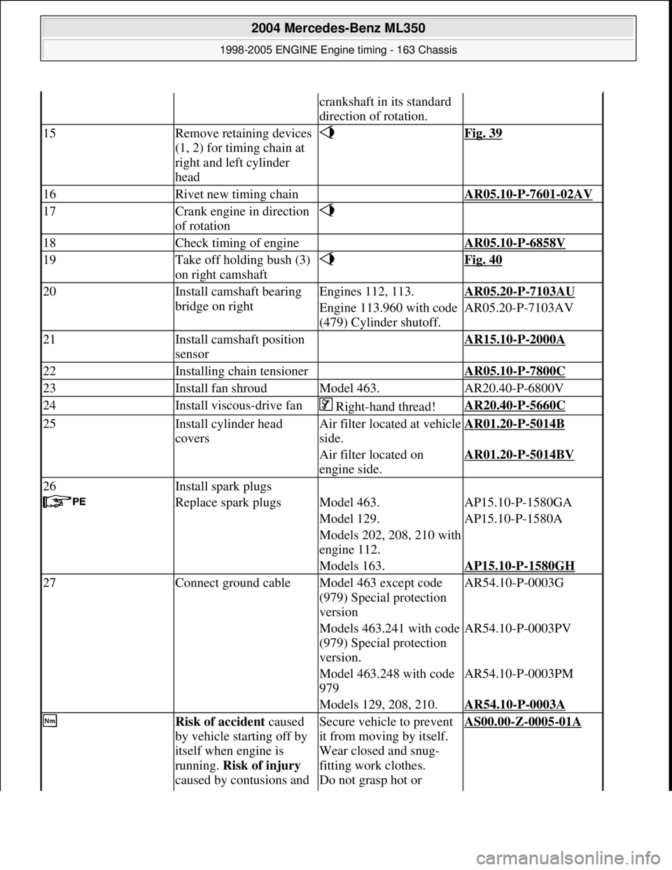
crankshaft in its standard
direction of rotation.
15Remove retaining devices
(1, 2) for timing chain at
right and left cylinder
head Fig. 39
16Rivet new timing chain AR05.10-P-7601-02AV
17Crank engine in direction
of rotation
18Check timing of engine AR05.10-P-6858V
19Take off holding bush (3)
on right camshaft Fig. 40
20Install camshaft bearing
bridge on rightEngines 112, 113.AR05.20-P-7103AU
Engine 113.960 with code
(479) Cylinder shutoff.AR05.20-P-7103AV
21Install camshaft position
sensor AR15.10-P-2000A
22Installing chain tensioner AR05.10-P-7800C
23Install fan shroudModel 463.AR20.40-P-6800V
24Install viscous-drive fan Right-hand thread!AR20.40-P-5660C
25Install cylinder head
coversAir filter locat ed at vehicle
side.AR01.20-P-5014B
Air filter located on
engine side.AR01.20-P-5014BV
26Install spark plugs
Replace spark plugsModel 463.AP15.10-P-1580GA
Model 129.AP15.10-P-1580A
Models 202, 208, 210 with
engine 112.
Models 163.AP15.10-P-1580GH
27Connect ground cableModel 463 except code
(979) Special protection
versionAR54.10-P-0003G
Models 463.241 with code
(979) Special protection
version.AR54.10-P-0003PV
Model 463.248 with code
979AR54.10-P-0003PM
Models 129, 208, 210.AR54.10-P-0003A
Risk of accident caused
by vehicle starting off by
itself when engine is
running. Risk of injury
caused by contusions and Secure vehicle to prevent
it from moving by itself.
Wear closed and snug-
fitting work clothes.
Do not grasp hot or AS00.00-Z-0005-01A
2004 Mercedes-Benz ML350
1998-2005 ENGINE Engine timing - 163 Chassis
me
Saturday, October 02, 2010 3:39:37 PMPage 38 © 2006 Mitchell Repair Information Company, LLC.
Page 2300 of 4133
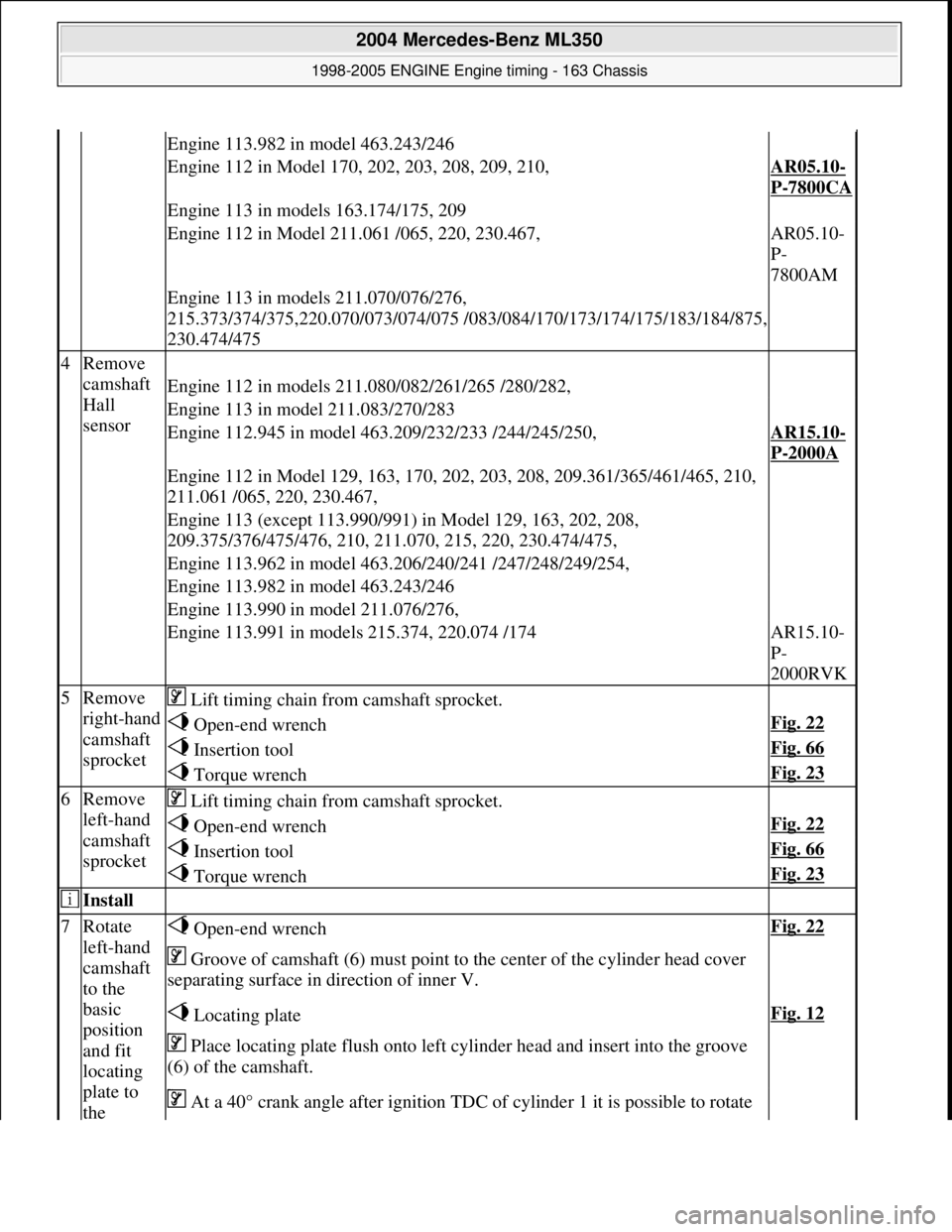
Engine 113.982 in model 463.243/246
Engine 112 in Model 170, 202, 203, 208, 209, 210,AR05.10-
P-7800CA
Engine 113 in models 163.174/175, 209
Engine 112 in Model 211.061 /065, 220, 230.467,AR05.10-
P-
7800AM
Engine 113 in models 211.070/076/276,
215.373/374/375,220.070/073/074/075 /083/ 084/170/173/174/175/183/184/875,
230.474/475
4Remove
camshaft
Hall
sensor
Engine 112 in models 211.080/082/261/265 /280/282,
Engine 113 in model 211.083/270/283
Engine 112.945 in model 463.209/232/233 /244/245/250,AR15.10-
P-2000A
Engine 112 in Model 129, 163, 170, 202, 203, 208, 209.361/365/461/465, 210,
211.061 /065, 220, 230.467,
Engine 113 (except 113.990/991) in Model 129, 163, 202, 208,
209.375/376/475/476, 210, 211.070, 215, 220, 230.474/475,
Engine 113.962 in model 463.206/240/241 /247/248/249/254,
Engine 113.982 in model 463.243/246
Engine 113.990 in model 211.076/276,
Engine 113.991 in models 215.374, 220.074 /174AR15.10-
P-
2000RVK
5Remove
right-hand
camshaft
sprocket Lift timing chain from camshaft sprocket.
Open-end wrenchFig. 22
Insertion toolFig. 66
Torque wrenchFig. 23
6Remove
left-hand
camshaft
sprocket Lift timing chain from camshaft sprocket.
Open-end wrenchFig. 22
Insertion toolFig. 66
Torque wrenchFig. 23
Install
7Rotate
left-hand
camshaft
to the
basic
position
and fit
locating
plate to
the Open-end wrenchFig. 22
Groove of camshaft (6) must point to the center of the cylinder head cover
separating surface in direction of inner V.
Locating plateFig. 12
Place locating plate flush onto left cylinder head and insert into the groove
(6) of the camshaft.
At a 40° crank angle afte r ignition TDC of cylinder 1 it is possible to rotate
2004 Mercedes-Benz ML350
1998-2005 ENGINE Engine timing - 163 Chassis
me
Saturday, October 02, 2010 3:39:38 PMPage 59 © 2006 Mitchell Repair Information Company, LLC.
Page 2301 of 4133
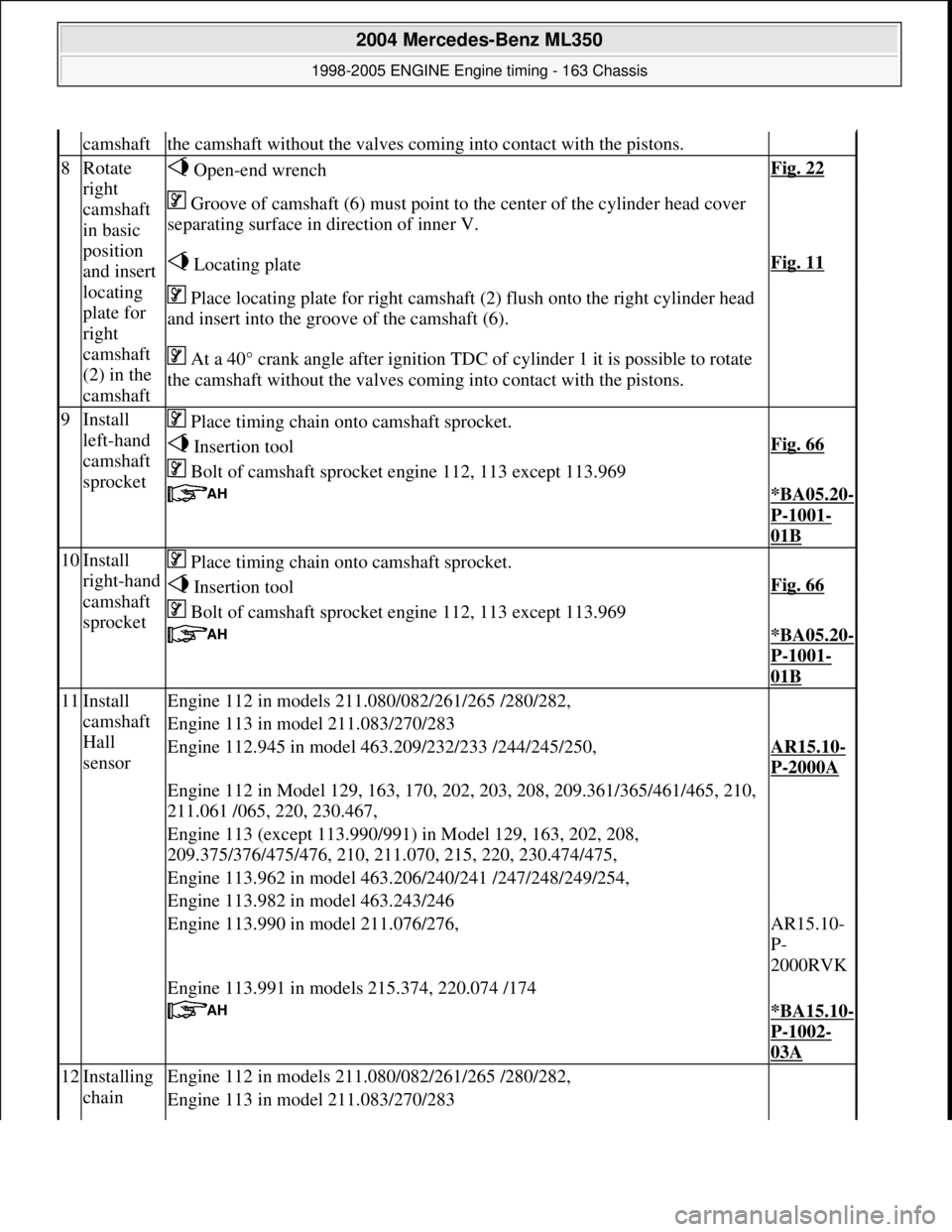
camshaftthe camshaft without th e valves coming into contact with the pistons.
8Rotate
right
camshaft
in basic
position
and insert
locating
plate for
right
camshaft
(2) in the
camshaft Open-end wrenchFig. 22
Groove of camshaft (6) must point to the center of the cylinder head cover
separating surface in direction of inner V.
Locating plateFig. 11
Place locating plate for right camshaft (2) flush onto the right cylinder head
and insert into the groove of the camshaft (6).
At a 40° crank angle afte r ignition TDC of cylinder 1 it is possible to rotate
the camshaft without th e valves coming into contact with the pistons.
9Install
left-hand
camshaft
sprocket Place timing chain onto camshaft sprocket.
Insertion toolFig. 66
Bolt of camshaft sprock et engine 112, 113 except 113.969
*BA05.20-
P-1001-
01B
10Install
right-hand
camshaft
sprocket Place timing chain onto camshaft sprocket.
Insertion toolFig. 66
Bolt of camshaft sprock et engine 112, 113 except 113.969
*BA05.20-
P-1001-
01B
11Install
camshaft
Hall
sensorEngine 112 in models 211.080/082/261/265 /280/282,
Engine 113 in model 211.083/270/283
Engine 112.945 in model 463.209/232/233 /244/245/250,AR15.10-
P-2000A
Engine 112 in Model 129, 163, 170, 202, 203, 208, 209.361/365/461/465, 210,
211.061 /065, 220, 230.467,
Engine 113 (except 113.990/991) in Model 129, 163, 202, 208,
209.375/376/475/476, 210, 211.070, 215, 220, 230.474/475,
Engine 113.962 in model 463.206/240/241 /247/248/249/254,
Engine 113.982 in model 463.243/246
Engine 113.990 in model 211.076/276,AR15.10-
P-
2000RVK
Engine 113.991 in models 215.374, 220.074 /174
*BA15.10-
P-1002-
03A
12Installing
chain Engine 112 in models 211.080/082/261/265 /280/282,
Engine 113 in model 211.083/270/283
2004 Mercedes-Benz ML350
1998-2005 ENGINE Engine timing - 163 Chassis
me
Saturday, October 02, 2010 3:39:38 PMPage 60 © 2006 Mitchell Repair Information Company, LLC.