1997 MERCEDES-BENZ ML350 sensor
[x] Cancel search: sensorPage 2085 of 4133
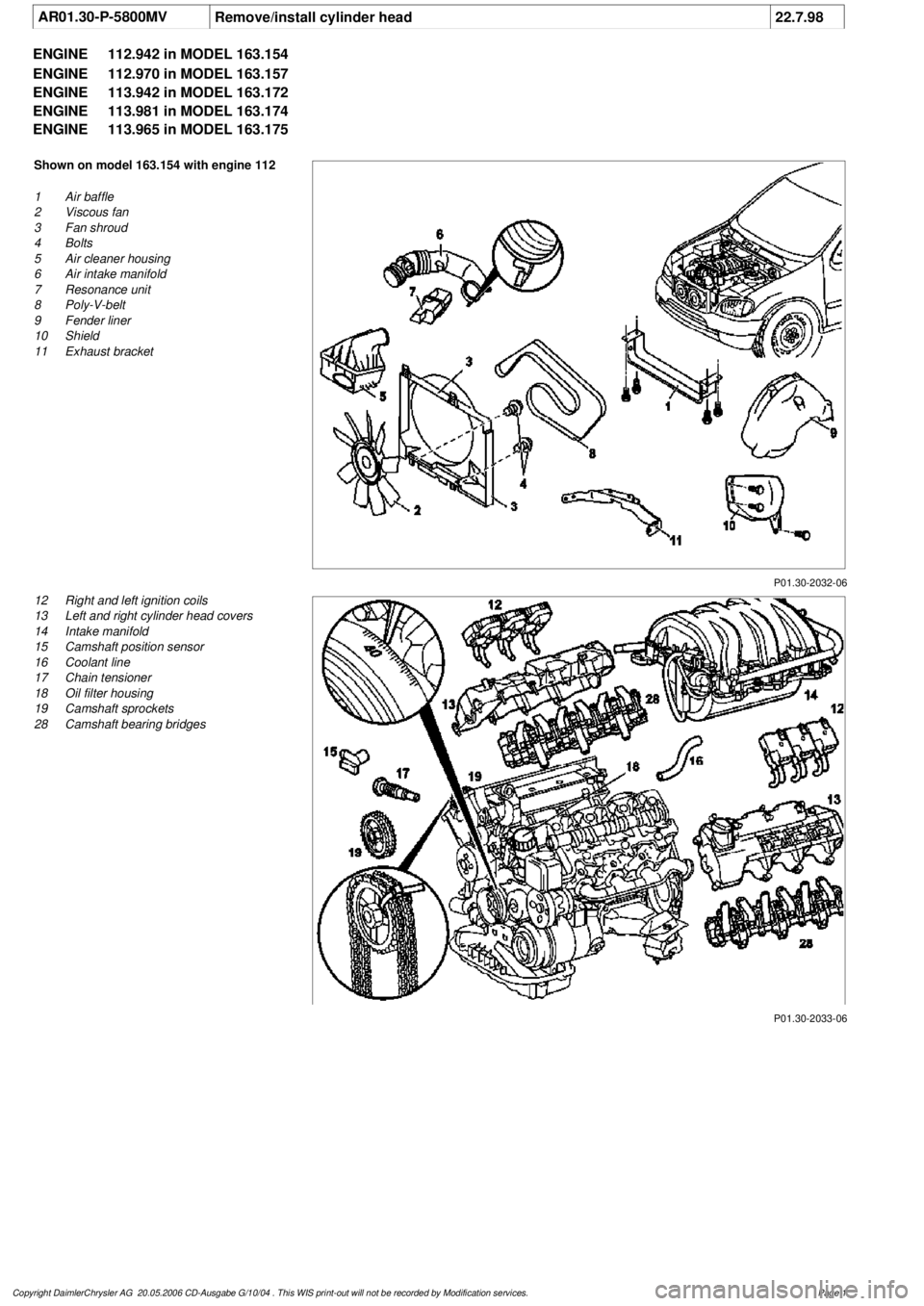
AR01.30-P-5800MV
Remove/install cylinder head
22.7.98
ENGINE
112.942 in MODEL 163.154
ENGINE
112.970 in MODEL 163.157
ENGINE
113.942 in MODEL 163.172
ENGINE
113.981 in MODEL 163.174
ENGINE
113.965 in MODEL 163.175
P01.30-2032-06
Shown on model 163.154 with engine 112
1
Air baffle
2
Viscous fan
3
Fan shroud
4
Bolts
5
Air cleaner housing
6
Air intake manifold
7
Resonance unit
8
Poly-V-belt
9
Fender liner
10
Shield
11
Exhaust bracket
P01.30-2033-06
12
Right and left ignition coils
13
Left and right cylinder head covers
14
Intake manifold
15
Camshaft position sensor
16
Coolant line
17
Chain tensioner
18
Oil filter housing
19
Camshaft sprockets
28
Camshaft bearing bridges
Copyright DaimlerChrysler AG 20.05.2006 CD-Ausgabe G/10/04 . This WIS print-out will not be recorde
d by Modification services.
Page 1
Page 2087 of 4133

8
Attach guard plate for radiator/condenser
y
Guard plate for radiator/condenser
Engine 606 in model 124,
Engine 606.961 in model 140,
Engine 112, 113, 604, 605, 611.960 in model
202,
Engine 602.983, 612.966 in model 461,
Engine 628.962, 612.965, 606.964, 112.945,
113.962/ 982 in model 463,
Engine 111, 112, 611.962, 612.962 in model
203,
Engine 112, 113, 611.961, 612.961, 613.961
in model 210,
Engine 112 in model 170,
Engine 112 in model 220,
Engine 113 in model 211, 215, 220,
Engine 112 in model 208,
Engine 112, 113, 612.963, 628.963 in model
163,
Engine 112.923 /943, 113.961 in model 129,
Engine 137, 275 in model 215, 220,
Engine 613.960, 628.960 in model 220,
Engine 113.992 in model 230.474,
Engine 271 in model 209, 203,
Engine 285.950 in model 240.078 /178,
Engine 612.967 in model 209.316,
Engine 648 in model 220
Engine 112.951 in model 639.601/603/ 605/
701 /703 /705 /801 /803 /805
Engine 646.983 /984 in model 639.601/
603 /605 /701 /703 /705 /801 /803 /805
Engine 646.982 in model 639.601/ 603/ 605/
701 /703 /705
WF58.50-P-0110-01A
9
Remove air cleaner housing (5)
10
Remove air intake pipe (6) with resonance
tube (7)
Separate connector of hot film mass air
flow sensor (HFM) for this step and unbolt air
intake pipe at cylinder head cover
The air intake pipe is attached at the rear
at the intake manifold with a plastic plate.
Do not damage the plastic strap.
Engine 112.942/ 970
AR07.07-P-1454A
Engine 113.942/ 965/ 981
AR07.07-P-1454MV
Danger!
Risk of explosion
caused by fuel igniting,
risk of poisoning
caused by inhaling and
swallowing fuel as well as
risk of injury
to
eyes and skin caused by contact with fuel.
No fire, sparks, open flames or smoking.
Pour fuels only into suitable and appropriately
marked containers.
Wear protective clothing when handling fuel.
AS47.00-Z-0001-01A
11
Disconnect fuel line at fuel rail
Release fuel pressure at service valve!
Collect fuel!
Engine 112:
#
*BA07.52-P-1001-01A
Engine 113:
#
*BA07.52-P-1001-01A
Pressure hose
*119589046300
12
Remove right and left ignition coils (12)
AR15.12-P-2003A
13
Remove right and left cylinder head covers (13)
AR01.20-P-5014B
14
Remove the intake manifold (14)
Installation:
On vehicles with engine
damage, the intake manifold must be
examined for swarfs before assembling and
any swarfs present must be removed, in order
to avoid consequential damage.
AR09.20-P-1310A
The intake manifold system must not be
disassembled.
Remove intake manifold with fuel distributor
15.1
Remove camshaft position sensor (15)
Only necessary if the right cylinder head is
removed.
AR15.10-P-2000A
Copyright DaimlerChrysler AG 20.05.2006 CD-Ausgabe G/10/04 . This WIS print-out will not be recorde
d by Modification services.
Page 3
Page 2093 of 4133
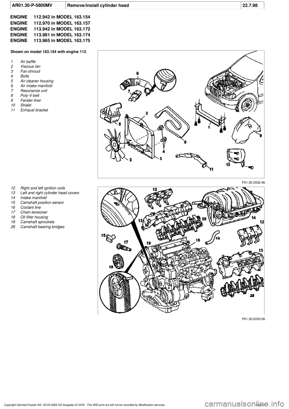
AR01.30-P-5800MV
Remove/install cylinder head
22.7.98
ENGINE
112.942 in MODEL 163.154
ENGINE
112.970 in MODEL 163.157
ENGINE
113.942 in MODEL 163.172
ENGINE
113.981 in MODEL 163.174
ENGINE
113.965 in MODEL 163.175
P01.30-2032-06
Shown on model 163.154 with engine 112
1
Air baffle
2
Viscous fan
3
Fan shroud
4
Bolts
5
Air cleaner housing
6
Air intake manifold
7
Resonance unit
8
Poly-V-belt
9
Fender liner
10
Shield
11
Exhaust bracket
P01.30-2033-06
12
Right and left ignition coils
13
Left and right cylinder head covers
14
Intake manifold
15
Camshaft position sensor
16
Coolant line
17
Chain tensioner
18
Oil filter housing
19
Camshaft sprockets
28
Camshaft bearing bridges
Copyright DaimlerChrysler AG 20.05.2006 CD-Ausgabe G/10/04 . This WIS print-out will not be recorde
d by Modification services.
Page 1
Page 2095 of 4133

8
Attach guard plate for radiator/condenser
y
Guard plate for radiator/condenser
Engine 606 in model 124,
Engine 606.961 in model 140,
Engine 112, 113, 604, 605, 611.960 in model
202,
Engine 602.983, 612.966 in model 461,
Engine 628.962, 612.965, 606.964, 112.945,
113.962/ 982 in model 463,
Engine 111, 112, 611.962, 612.962 in model
203,
Engine 112, 113, 611.961, 612.961, 613.961
in model 210,
Engine 112 in model 170,
Engine 112 in model 220,
Engine 113 in model 211, 215, 220,
Engine 112 in model 208,
Engine 112, 113, 612.963, 628.963 in model
163,
Engine 112.923 /943, 113.961 in model 129,
Engine 137, 275 in model 215, 220,
Engine 613.960, 628.960 in model 220,
Engine 113.992 in model 230.474,
Engine 271 in model 209, 203,
Engine 285.950 in model 240.078 /178,
Engine 612.967 in model 209.316,
Engine 648 in model 220
Engine 112.951 in model 639.601/603/ 605/
701 /703 /705 /801 /803 /805
Engine 646.983 /984 in model 639.601/
603 /605 /701 /703 /705 /801 /803 /805
Engine 646.982 in model 639.601/ 603/ 605/
701 /703 /705
WF58.50-P-0110-01A
9
Remove air cleaner housing (5)
10
Remove air intake pipe (6) with resonance
tube (7)
Separate connector of hot film mass air
flow sensor (HFM) for this step and unbolt air
intake pipe at cylinder head cover
The air intake pipe is attached at the rear
at the intake manifold with a plastic plate.
Do not damage the plastic strap.
Engine 112.942/ 970
AR07.07-P-1454A
Engine 113.942/ 965/ 981
AR07.07-P-1454MV
Danger!
Risk of explosion
caused by fuel igniting,
risk of poisoning
caused by inhaling and
swallowing fuel as well as
risk of injury
to
eyes and skin caused by contact with fuel.
No fire, sparks, open flames or smoking.
Pour fuels only into suitable and appropriately
marked containers.
Wear protective clothing when handling fuel.
AS47.00-Z-0001-01A
11
Disconnect fuel line at fuel rail
Release fuel pressure at service valve!
Collect fuel!
Engine 112:
#
*BA07.52-P-1001-01A
Engine 113:
#
*BA07.52-P-1001-01A
Pressure hose
*119589046300
12
Remove right and left ignition coils (12)
AR15.12-P-2003A
13
Remove right and left cylinder head covers (13)
AR01.20-P-5014B
14
Remove the intake manifold (14)
Installation:
On vehicles with engine
damage, the intake manifold must be
examined for swarfs before assembling and
any swarfs present must be removed, in order
to avoid consequential damage.
AR09.20-P-1310A
The intake manifold system must not be
disassembled.
Remove intake manifold with fuel distributor
15.1
Remove camshaft position sensor (15)
Only necessary if the right cylinder head is
removed.
AR15.10-P-2000A
Copyright DaimlerChrysler AG 20.05.2006 CD-Ausgabe G/10/04 . This WIS print-out will not be recorde
d by Modification services.
Page 3
Page 2107 of 4133

GF54.30-P-3028GH
Displaying coolant level, function
28.6.99
MODEL
163 as of 1.3.99
Function prerequisite
Engine: ON
Function
If the coolant level drops below the minimum mark the low ECL
indicator lamp (A1p11) is illuminated.
To record the coolant level the instrument cluster (A1) is connected
direct to the
coolant level indicator electronic switch (S41)
via two
cables. The
coolant level indicator electronic switch (S41)
consists of two electrodes.
D
If the
level is correct
both electrodes are immersed in the
coolant. The coolant serves as a dielectric between the
electrodes.
D
If the coolant level is below the minimum mark the electrodes of
the sensor are no longer immersed in the coolant. There is only
air between the electrodes as a dielectric. Evaluation
The instrument cluster (A1) sends test pulses to the sensor for
a period of one millisecond. These pulses are deformed
differently depending on the dielectric (air or coolant).
The instrument cluster (A1) evaluates the pulse shape and, if
the coolant level is below the minimum (electrodes are
completely in air), actuates the low ECL indicator lamp (A1p11)
after a delay of
approx. 60 seconds
.
The delay serves to prevent the indicator lamp flickering due to
the coolant moving from side to side on corners or off-road.
Diagnosis
Diagnosis is carried out, as described in the Diagnosis Manual, via
the simulation of the
coolant level indicator electronic switch (S41)
by a resistance.
Coolant level switch,
location/task/design/function
GF54.30-P-4103GH
Copyright DaimlerChrysler AG 04.06.2006 CD-Ausgabe G/10/04 . This WIS print-out will not be recorde
d by Modification services.
Page 1
Page 2144 of 4133
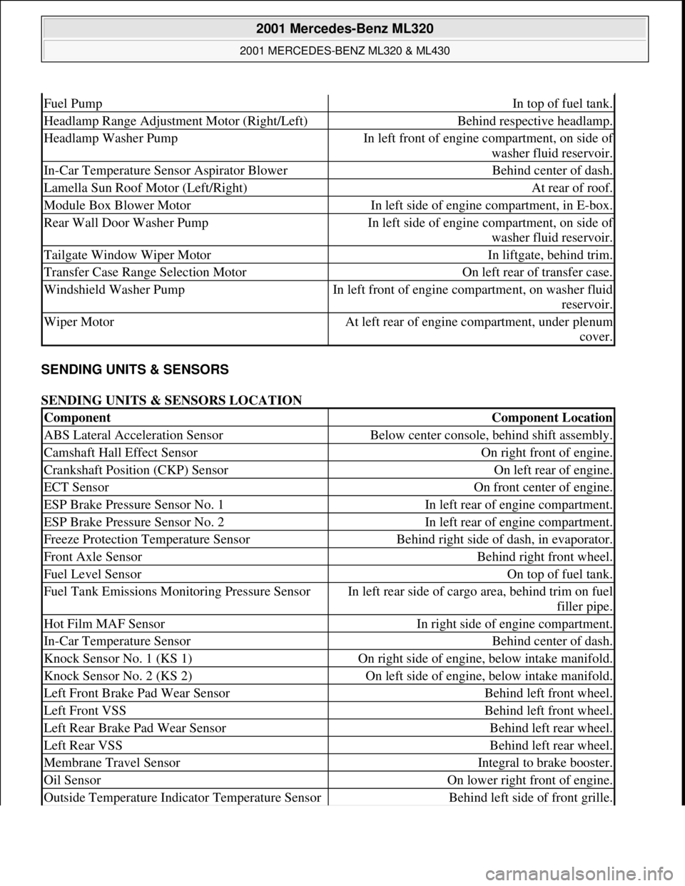
SENDING UNITS & SENSORS
SENDING UNITS & SENSORS LOCATION
Fuel PumpIn top of fuel tank.
Headlamp Range Adjustment Motor (Right/Left)Behind respective headlamp.
Headlamp Washer PumpIn left front of engine compartment, on side of
washer fluid reservoir.
In-Car Temperature Sensor Aspirator BlowerBehind center of dash.
Lamella Sun Roof Motor (Left/Right)At rear of roof.
Module Box Blower MotorIn left side of engine compartment, in E-box.
Rear Wall Door Washer PumpIn left side of engine compartment, on side of
washer fluid reservoir.
Tailgate Window Wiper MotorIn liftgate, behind trim.
Transfer Case Range Selection MotorOn left rear of transfer case.
Windshield Washer PumpIn left front of engine compartment, on washer fluid
reservoir.
Wiper MotorAt left rear of engine compartment, under plenum
cover.
ComponentComponent Location
ABS Lateral Acceleration SensorBelow center console, behind shift assembly.
Camshaft Hall Effect SensorOn right front of engine.
Crankshaft Position (CKP) SensorOn left rear of engine.
ECT SensorOn front center of engine.
ESP Brake Pressure Sensor No. 1In left rear of engine compartment.
ESP Brake Pressure Sensor No. 2In left rear of engine compartment.
Freeze Protection Temperature SensorBehind right side of dash, in evaporator.
Front Axle SensorBehind right front wheel.
Fuel Level SensorOn top of fuel tank.
Fuel Tank Emissions Monitoring Pressure SensorIn left rear side of cargo area, behind trim on fuel
filler pipe.
Hot Film MAF SensorIn right side of engine compartment.
In-Car Temperature SensorBehind center of dash.
Knock Sensor No. 1 (KS 1)On right side of engine, below intake manifold.
Knock Sensor No. 2 (KS 2)On left side of engine, below intake manifold.
Left Front Brake Pad Wear SensorBehind left front wheel.
Left Front VSSBehind left front wheel.
Left Rear Brake Pad Wear SensorBehind left rear wheel.
Left Rear VSSBehind left rear wheel.
Membrane Travel SensorIntegral to brake booster.
Oil SensorOn lower right front of engine.
Outside Temperature Indicator Temperature SensorBehind left side of front grille.
2001 Mercedes-Benz ML320
2001 MERCEDES-BENZ ML320 & ML430
me
Saturday, October 02, 2010 3:21:17 PMPage 4 © 2006 Mitchell Repair Information Company, LLC.
Page 2145 of 4133
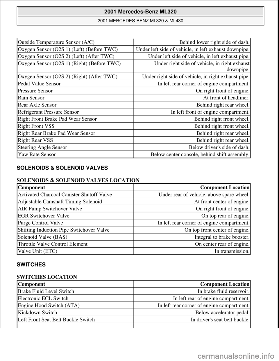
SOLENOIDS & SOLENOID VALVES
SOLENOIDS & SOLENOID VALVES LOCATION
SWITCHES
SWITCHES LOCATION
Outside Temperature Sensor (A/C)Behind lower right side of dash.
Oxygen Sensor (O2S 1) (Left) (Before TWC)Under left side of vehicle, in left exhaust downpipe.
Oxygen Sensor (O2S 2) (Left) (After TWC)Under left side of vehicle, in left exhaust pipe.
Oxygen Sensor (O2S 1) (Right) (Before TWC)Under right side of vehicle, in right exhaust
downpipe.
Oxygen Sensor (O2S 2) (Right) (After TWC)Under right side of vehicle, in right exhaust pipe.
Pedal Value SensorIn left rear corner of engine compartment.
Pressure SensorOn right front of engine.
Rain SensorAt front of headliner.
Rear Axle SensorBehind right rear wheel.
Refrigerant Pressure SensorIn left front of engine compartment.
Right Front Brake Pad Wear SensorBehind right front wheel.
Right Front VSSBehind right front wheel.
Right Rear Brake Pad Wear SensorBehind right rear wheel.
Right Rear VSSBehind right rear wheel.
Steering Angle SensorBelow driver's side of dash.
Yaw Rate SensorBelow center console, behind shift assembly.
ComponentComponent Location
Activated Charcoal Canister Shutoff ValveUnder rear of vehicle, above spare wheel.
Adjustable Camshaft Timing SolenoidAt front center of engine.
AIR Pump Switchover ValveOn right front of engine.
EGR Switchover ValveOn top rear of engine.
Purge Control ValveIn left rear corner of engine compartment.
Shifting Induction Pipe Switchover ValveOn top front center of engine.
Solenoid Valve (BAS)Integral to brake booster.
Throttle Valve Control ElementOn center rear of engine.
Valve Unit (ETC)In transmission.
ComponentComponent Location
Brake Fluid Level SwitchIn brake fluid reservoir.
Electronic ECL SwitchIn left rear of engine compartment.
Engine Hood Switch (ATA)In left rear corner of engine compartment.
Kickdown SwitchBelow accelerator pedal.
Left Front Seat Belt Buckle SwitchIn driver's seat belt buckle.
2001 Mercedes-Benz ML320
2001 MERCEDES-BENZ ML320 & ML430
me
Saturday, October 02, 2010 3:21:17 PMPage 5 © 2006 Mitchell Repair Information Company, LLC.
Page 2149 of 4133
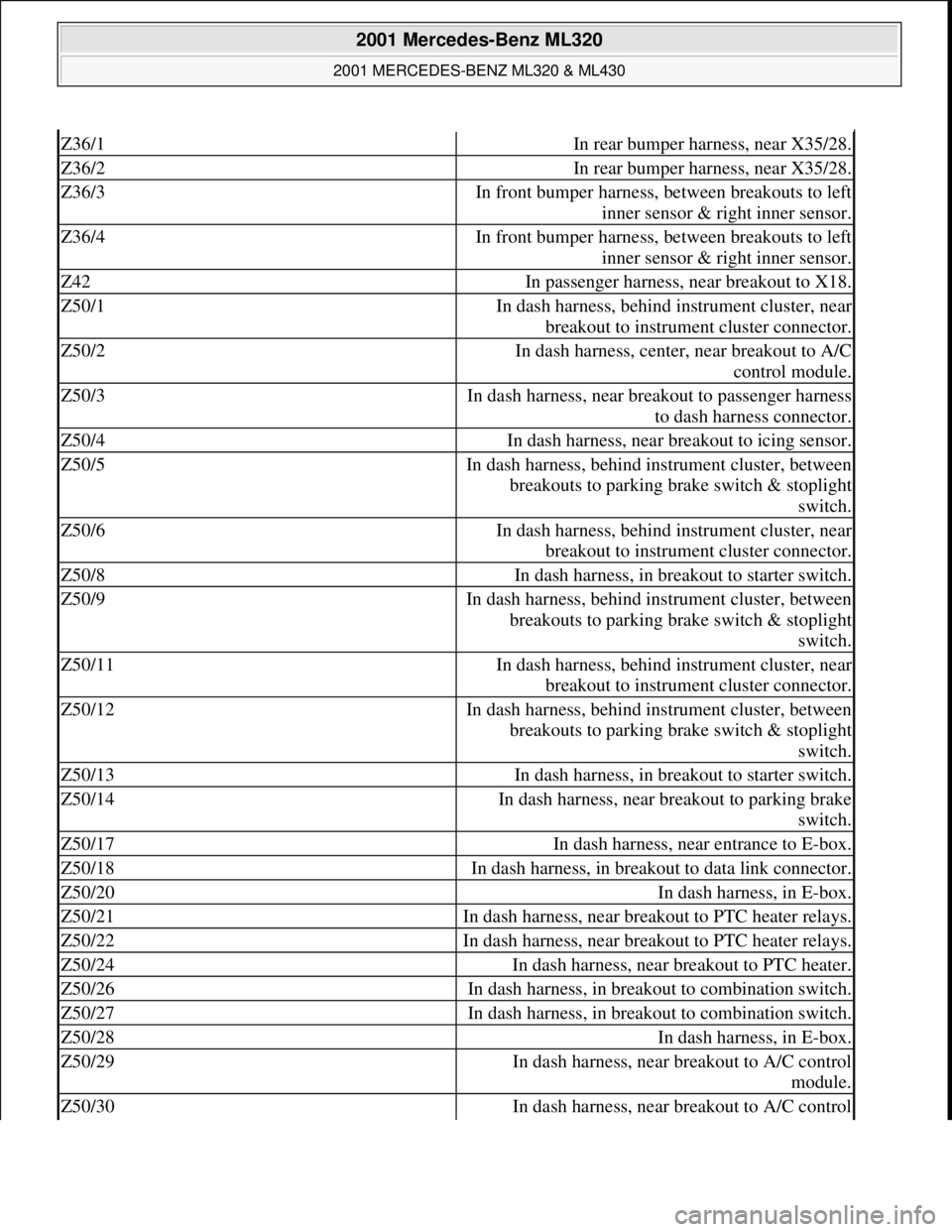
Z36/1In rear bumper harness, near X35/28.
Z36/2In rear bumper harness, near X35/28.
Z36/3In front bumper harness, between breakouts to left
inner sensor & right inner sensor.
Z36/4In front bumper harness, between breakouts to left
inner sensor & right inner sensor.
Z42In passenger harness, near breakout to X18.
Z50/1In dash harness, behind instrument cluster, near
breakout to instrument cluster connector.
Z50/2In dash harness, center, near breakout to A/C
control module.
Z50/3In dash harness, near breakout to passenger harness
to dash harness connector.
Z50/4In dash harness, near breakout to icing sensor.
Z50/5In dash harness, behind instrument cluster, between
breakouts to parking brake switch & stoplight
switch.
Z50/6In dash harness, behind instrument cluster, near
breakout to instrument cluster connector.
Z50/8In dash harness, in breakout to starter switch.
Z50/9In dash harness, behind instrument cluster, between
breakouts to parking brake switch & stoplight
switch.
Z50/11In dash harness, behind instrument cluster, near
breakout to instrument cluster connector.
Z50/12In dash harness, behind instrument cluster, between
breakouts to parking brake switch & stoplight
switch.
Z50/13In dash harness, in breakout to starter switch.
Z50/14In dash harness, near breakout to parking brake
switch.
Z50/17In dash harness, near entrance to E-box.
Z50/18In dash harness, in breakout to data link connector.
Z50/20In dash harness, in E-box.
Z50/21In dash harness, near breakout to PTC heater relays.
Z50/22In dash harness, near breakout to PTC heater relays.
Z50/24In dash harness, near breakout to PTC heater.
Z50/26In dash harness, in breakout to combination switch.
Z50/27In dash harness, in breakout to combination switch.
Z50/28In dash harness, in E-box.
Z50/29In dash harness, near breakout to A/C control
module.
Z50/30In dash harness, near breakout to A/C control
2001 Mercedes-Benz ML320
2001 MERCEDES-BENZ ML320 & ML430
me
Saturday, October 02, 2010 3:21:17 PMPage 9 © 2006 Mitchell Repair Information Company, LLC.