1997 MERCEDES-BENZ ML350 sensor
[x] Cancel search: sensorPage 1996 of 4133
AR88.20-P-2000GJ
Remove/install front bumper
26.2.01
MODEL
163.113 /154 #A as of 289565,
163.113 #X as of 754620,
163.128 /154 /157 /175 except CODE (U49) Styling package
P88.20-2203-09
Remove/install
1.1
Remove brush guard together with underride
guard
If installed.
AR88.30-P-2000-01GI
*BA88.30-P-1003-01A
*BA88.30-P-1015-01A
*BA88.30-P-1016-01A
2
Remove fog lamps
AR82.10-P-5103GI
3
Remove front bumper grille.
Carefully remove bumper grille so that
bumper grille and mounts cannot be damaged.
Remove with correspondingly formed hook.
Pulling hook
*140589023300
4
Remove outdoor temperature sensor from
bumper.
5
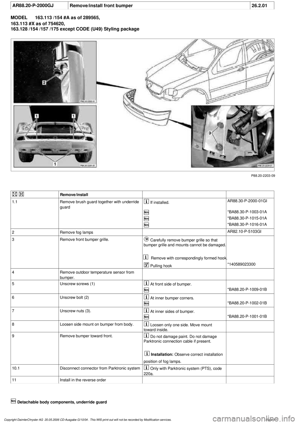
Unscrew screws (1)
At front side of bumper.
*BA88.20-P-1009-01B
6
Unscrew bolt (2)
At inner bumper corners.
*BA88.20-P-1002-01B
7
Unscrew nuts (3).
At inner sides of bumper.
*BA88.20-P-1001-01B
8
Loosen side mount on bumper from body.
Loosen only one side. Move mount
toward inside.
9
Remove bumper toward front.
Do not damage paint. Do not damage
Parktronic connection cable if present.
Installation:
Observe correct installation
position of fog lamps.
10.1
Disconnect connector from Parktronic system
Only with Parktronic system (PTS), code
220a.
11
Install in the reverse order
Detachable body components, underride guard
Copyright DaimlerChrysler AG 20.05.2006 CD-Ausgabe G/10/04 . This WIS print-out will not be recorde
d by Modification services.
Page 1
Page 2030 of 4133
AR09.41-P-6817MM
Removing and installing charge air cooler
10.11.99
ENGINE
612.963 in MODEL 163.113
P09.41-2024-09
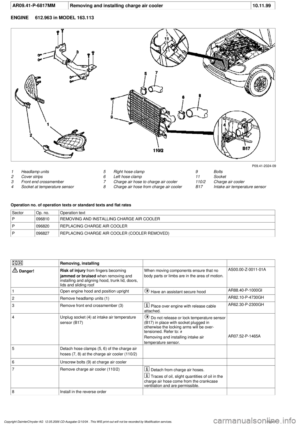
1
Headlamp units
2
Cover strips
3
Front end crossmember
4
Socket at temperature sensor
9
Bolts
11
Socket
110/2
Charge air cooler
B17
Intake air temperature sensor
5
Right hose clamp
6
Left hose clamp
7
Charge air hose to charge air cooler
8
Charge air hose from charge air cooler
Operation no. of operation texts or standard texts and flat rates
Sector
Op. no.
Operation text
P
096810
REMOVING AND INSTALLING CHARGE AIR COOLER
P
096820
REPLACING CHARGE AIR COOLER
P
096827
REPLACING CHARGE AIR COOLER (COOLER REMOVED)
Removing, installing
Danger!
Risk of injury
from fingers becoming
jammed or bruised
when removing and
installing and aligning hood, trunk lid, doors,
lids and sliding roof
When moving components ensure that no
body parts or limbs are in the area of motion.
AS00.00-Z-0011-01A
1
Open engine hood and position upright
Have an assistant secure hood
AR88.40-P-1000GI
2
Remove headlamp units (1)
AR82.10-P-4730GH
3
Remove front end crossmember (3)
Place over engine with release cable
attached.
AR62.30-P-2300GH
4
Unplug socket (4) at intake air temperature
sensor (B17)
Do not release or lock temperature sensor
(B17) in place with socket plugged in
otherwise the locking arms will be over-
tensioned. Refer to:
#
Removing and installing intake air
temperature sensor.
AR07.52-P-1465A
5
Detach hose clamps (5, 6) of the charge air
hoses (7, 8) at the charge air cooler (110/2)
6
Unscrew bolts (9) at charge air cooler
7
Remove charge air cooler (110/2)
Detach from charge air hoses.
Traces of oil, slight quantities of oil in the
charge air hose come from the crankcase
ventilation and are permissible.
8
Install in the reverse order
Copyright DaimlerChrysler AG 12.05.2006 CD-Ausgabe G/10/04 . This WIS print-out will not be recorde
d by Modification services.
Page 1
Page 2032 of 4133
AR09.41-P-6817MM
Removing and installing charge air cooler
10.11.99
ENGINE
612.963 in MODEL 163.113
P09.41-2024-09
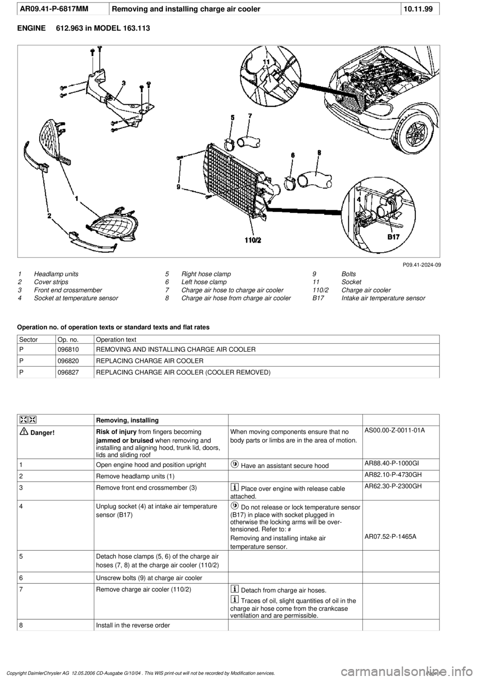
1
Headlamp units
2
Cover strips
3
Front end crossmember
4
Socket at temperature sensor
9
Bolts
11
Socket
110/2
Charge air cooler
B17
Intake air temperature sensor
5
Right hose clamp
6
Left hose clamp
7
Charge air hose to charge air cooler
8
Charge air hose from charge air cooler
Operation no. of operation texts or standard texts and flat rates
Sector
Op. no.
Operation text
P
096810
REMOVING AND INSTALLING CHARGE AIR COOLER
P
096820
REPLACING CHARGE AIR COOLER
P
096827
REPLACING CHARGE AIR COOLER (COOLER REMOVED)
Removing, installing
Danger!
Risk of injury
from fingers becoming
jammed or bruised
when removing and
installing and aligning hood, trunk lid, doors,
lids and sliding roof
When moving components ensure that no
body parts or limbs are in the area of motion.
AS00.00-Z-0011-01A
1
Open engine hood and position upright
Have an assistant secure hood
AR88.40-P-1000GI
2
Remove headlamp units (1)
AR82.10-P-4730GH
3
Remove front end crossmember (3)
Place over engine with release cable
attached.
AR62.30-P-2300GH
4
Unplug socket (4) at intake air temperature
sensor (B17)
Do not release or lock temperature sensor
(B17) in place with socket plugged in
otherwise the locking arms will be over-
tensioned. Refer to:
#
Removing and installing intake air
temperature sensor.
AR07.52-P-1465A
5
Detach hose clamps (5, 6) of the charge air
hoses (7, 8) at the charge air cooler (110/2)
6
Unscrew bolts (9) at charge air cooler
7
Remove charge air cooler (110/2)
Detach from charge air hoses.
Traces of oil, slight quantities of oil in the
charge air hose come from the crankcase
ventilation and are permissible.
8
Install in the reverse order
Copyright DaimlerChrysler AG 12.05.2006 CD-Ausgabe G/10/04 . This WIS print-out will not be recorde
d by Modification services.
Page 1
Page 2042 of 4133
3. Normalize side power windows. See NORMALIZING POWER WINDOWS .
4. Start engine and run at idle. Turn steering wheel from one lock position to the other to activate steering
angle sensor. Center steering wheel. Message "EI. STAB. PROGRAM GO TO GARAGE" should erase
from multifunction display panel.
5. If equipped, normalize tilting/sliding roof. See NORMALIZING TILTING/SLIDING ROOF
.
6. If equipped, normalize memory power seats, steering column and outside mirror if components are
installed. See NORMALIZING MEMORY POWER SEATS, STEERING COLUMN & OUTSIDE
MIRROR .
Normalizing Power Windows
1. Completely close each window with manual switch. Hold switch in closed position for .3 second.
2. Repeat procedure for each power window.
Normalizing Memory Power Seats, Steering Column & Outside Mirror
1. Using manual switch, move seat to each end position and hold for .3 second. Repeat procedure for each
switch except rear stop of backrest.
2. Repeat procedure for end positions of steering wheel and outside mirrors.
Normalizing Tilting/Sliding Roof
Open roof with SR switch until mechanical stop is reached. Continue to press switch for .5 seconds.
Setting Time
1. Use bottom left button on steering wheel to scroll through menus on instrument cluster to "Settings"
menu.
2. Move selection marker with + or - button to "Time" submenu.
3. Press up or down arrows to "Clock, hours" setting. Confirm selection marker is on the hour setting.
4. Press + or - to set hour. Press reset knob in instrument cluster to confirm.
5. Move selection marker with + or - button to "Time" submenu.
6. Press up or down arrows to "Clock, minutes" setting. Confirm selection marker is on the minutes setting.
7. Press + or - to set minute. Press reset knob in instrument cluster to confirm.
TESTING
If generator malfunctions, check for Diagnostic Trouble Codes (DTCs) in Motor Electronics Sequential Fuel
Injection (ME-SFI) system. See appropriate SELF-DIAGNOSTICS article in ENGINE PERFORMANCE. If
cause of generator malfunction is not engine performance related, replace generator.
RETRIEVING & ERASING DIAGNOSTIC TROUBLE CODES
NOTE: Before replacing any component that scan tool suggests are faulty, ensure that
all wiring connections and harness connectors are okay. Ensure that power and
2001 Mercedes-Benz ML320
2001-04 STARTING & CHARGING SYSTEMS Generators & Regulators - 163 Chassis
me
Saturday, October 02, 2010 3:20:32 PMPage 8 © 2006 Mitchell Repair Information Company, LLC.
Page 2066 of 4133

GF54.30-P-2004A
Control buttons, location/task
24.10.96
MODEL
129, 140 as of 1.6.96,
163, 170
The instrument cluster has two control buttons which are on the left
or right next to the speedometer.
The
right control button
is used to adjust the time (refer to Owner's
Manual).
-----------------------------------------------------------------------------------------
The
left control button
is used
D
to regulate the instrument illumination
D
to activate the display illumination
D
to reset the trip odometer display
D
to operate the maintenance display (model 170 only bis 05.97)
D
to operate the Active Service System ASSYST (as of 06.97)
-----------------------------------------------------------------------------------------
n
Purpose/function of terminal 58d, instrument
display illumination
Engines 112, 113, 611 (engines with oil
sensor)
GF54.30-P-3008A
n
Electronic clock
GF54.30-P-3011A
n
Active Service System (ASSYST)
GF00.20-P-0003-01A
Operating instructions, resetting
Model 210 as of 01.03.97 with engines M111,
OM 602, OM 604, OM 605 and
OM 606
As of 06/97 models 129, 140, 170, 202 except
engines 112, 113, 611
(valid for engines with oil level switch)
GF00.20-P-0003-01B
Copyright DaimlerChrysler AG 05.06.2006 CD-Ausgabe G/10/04 . This WIS print-out will not be recorde
d by Modification services.
Page 1
Page 2080 of 4133
Crankshaft Position Sensor DIY
hopefully this will help others with what appears to be a common stalling issue in the ML series.
Location:
--------
It's on the rear of the engine where the engine mates with the tranny on the driver's side. There are 2
types. Be sure to get the correct one
Here it is:
1) Get
CPS
at dealer, its a VIN specific part. $125 from my local stealer.
2) Tools needed: Socket screwdriver, Good lighting (portable) shop lights, size 8 outside torx socket,
maybe a ratche
t and extentions depending on your flexibility, magnetic part retrieval tool (skip this at
your peril), bath towel, and long sleeve shirt, step stool, blue thread locker (optional)
3) Open hood and remove engine cover, it just pulls off and on
4) Set wor
k light(s) toward back of engine, lighting behind drivers cylinder head
5) Set bath towel on front of ML to kneel on of your knees will die, wearing long sleeve shirt or your
wrists will be cut.
6) Climb up on towel and look behind engine from above and
right (see .jpg), finding torx attachment
holding your
CPS
.
7) Remove torx screw and pull out
CPS
, disconnect one way connector (wiring)
8) Replace with new (leaving wire detached for now)
9) This is the hardest step by far, and requires patience and fl exibility. Apply some thread locker and
insert screw and start the threads. Tighten with torx on socket screwdriver. This step took about 1/2
hour and numerous dropped screws and retrievals with mag tool.
10) Attach wiring to
CPS
11) Reinstall engine cov
er
12) Clean up tools, towel and lights and everything
13) Drink beer and toast yourself for saving yourself at least $100 and a day of your time dropping off
and picking up cars at shop
Hope this helps someone in the community.
Dickie
00 ML 32
0
Page 2081 of 4133
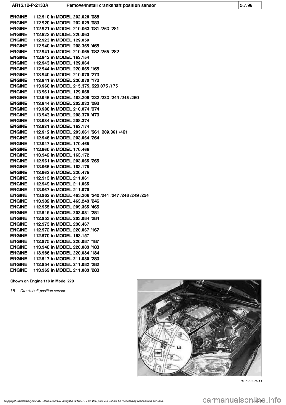
AR15.12-P-2133A
Remove/install crankshaft position sensor
5.7.96
ENGINE
112.910 in MODEL 202.026 /086
ENGINE
112.920 in MODEL 202.029 /089
ENGINE
112.921 in MODEL 210.063 /081 /263 /281
ENGINE
112.922 in MODEL 220.063
ENGINE
112.923 in MODEL 129.059
ENGINE
112.940 in MODEL 208.365 /465
ENGINE
112.941 in MODEL 210.065 /082 /265 /282
ENGINE
112.942 in MODEL 163.154
ENGINE
112.943 in MODEL 129.064
ENGINE
112.944 in MODEL 220.065 /165
ENGINE
113.940 in MODEL 210.070 /270
ENGINE
113.941 in MODEL 220.070 /170
ENGINE
113.960 in MODEL 215.375, 220.075 /175
ENGINE
113.961 in MODEL 129.068
ENGINE
112.945 in MODEL 463.209 /232 /233 /244 /245 /250
ENGINE
113.944 in MODEL 202.033 /093
ENGINE
113.980 in MODEL 210.074 /274
ENGINE
113.943 in MODEL 208.370 /470
ENGINE
113.984 in MODEL 208.374
ENGINE
113.981 in MODEL 163.174
ENGINE
112.912 in MODEL 203.061 /261, 209.361 /461
ENGINE
112.946 in MODEL 203.064 /264
ENGINE
112.947 in MODEL 170.465
ENGINE
112.960 in MODEL 170.466
ENGINE
113.942 in MODEL 163.172
ENGINE
112.961 in MODEL 203.065 /265
ENGINE
113.965 in MODEL 163.175
ENGINE
113.963 in MODEL 230.475
ENGINE
112.913 in MODEL 211.061
ENGINE
112.949 in MODEL 211.065
ENGINE
113.967 in MODEL 211.070
ENGINE
113.962 in MODEL 463.206 /240 /241 /247 /248 /249 /254
ENGINE
113.982 in MODEL 463.243 /246
ENGINE
112.955 in MODEL 209.365 /465
ENGINE
112.916 in MODEL 203.081 /281
ENGINE
112.953 in MODEL 203.084 /284
ENGINE
112.973 in MODEL 230.467
ENGINE
112.972 in MODEL 220.067 /167
ENGINE
112.970 in MODEL 163.157
ENGINE
112.975 in MODEL 220.087 /187
ENGINE
113.948 in MODEL 220.083 /183
ENGINE
113.966 in MODEL 220.084 /184
ENGINE
112.917 in MODEL 211.080 /280
ENGINE
112.954 in MODEL 211.082 /282
ENGINE
113.969 in MODEL 211.083 /283
P15.12-0275-11
Shown on Engine 113 in Model 220
L5
Crankshaft position sensor
Copyright DaimlerChrysler AG 29.05.2006 CD-Ausgabe G/10/04 . This WIS print-out will not be recorde
d by Modification services.
Page 1
Page 2082 of 4133

Remove/Install
1.1
Remove engine compartment cover with
integrated air cleaner
All except Engine 112.960 in Model 170.466,
Engine 112.961 in Model 203.065/ 265
Remove air cleaner by lifting vertically up
and away from the cylinder head covers.
Installation:
With sliding compound,
slightly moisten the rubber retainers on the
cylinder head covers and the sealing ring of
the hot film mass air flow sensor in the air
cleaner housing.
1.2
Remove air cleaner housing
Engine 112.960 in Model 170.466
Engine 112.961 in Model 203.065/265
AR09.10-P-1150SVK
2
Remove crankshaft position sensor (L5)
*BA15.10-P-1001-03A
3
Install in the reverse order
4.1
Reinitialize crankshaft position sensor (L5)
using STAR DIAGNOSIS
If the crankshaft position sensor (L5) was
replaced, a re-initialization must be carried
out with STAR DIAGNOSIS in the "Control
unit adaptations" menu item.
Diagnosis system STAR DIAGNOSIS
*WE58.40-Z-1013-06A
Position sensor
Number
Designation
Engine
112.910/911/912/
913/914/915/
916/917/920/
921/922/923/
940/941/942/
943/944/945/
946/947/949/
951/953/954/
955/960/961/
970/972/973/975
Engine
113.940/941/
942/943/944/
948/960/961/
962/963/965/
966/967/968/
969/980/981/
982/984/986/
992/993
BA15.10-P-1001-03A
Crankshaft position sensor to engine block
Nm
88
Workshop equipment/MB testers
(see Workshop Equipment Manual)
WE58.40-Z-1013-06A
Compact STAR DIAGNOSIS system for passenger cars, order number 6511 1801 00
Copyright DaimlerChrysler AG 29.05.2006 CD-Ausgabe G/10/04 . This WIS print-out will not be recorde
d by Modification services.
Page 2