1997 MERCEDES-BENZ ML350 sensor
[x] Cancel search: sensorPage 2150 of 4133
module.
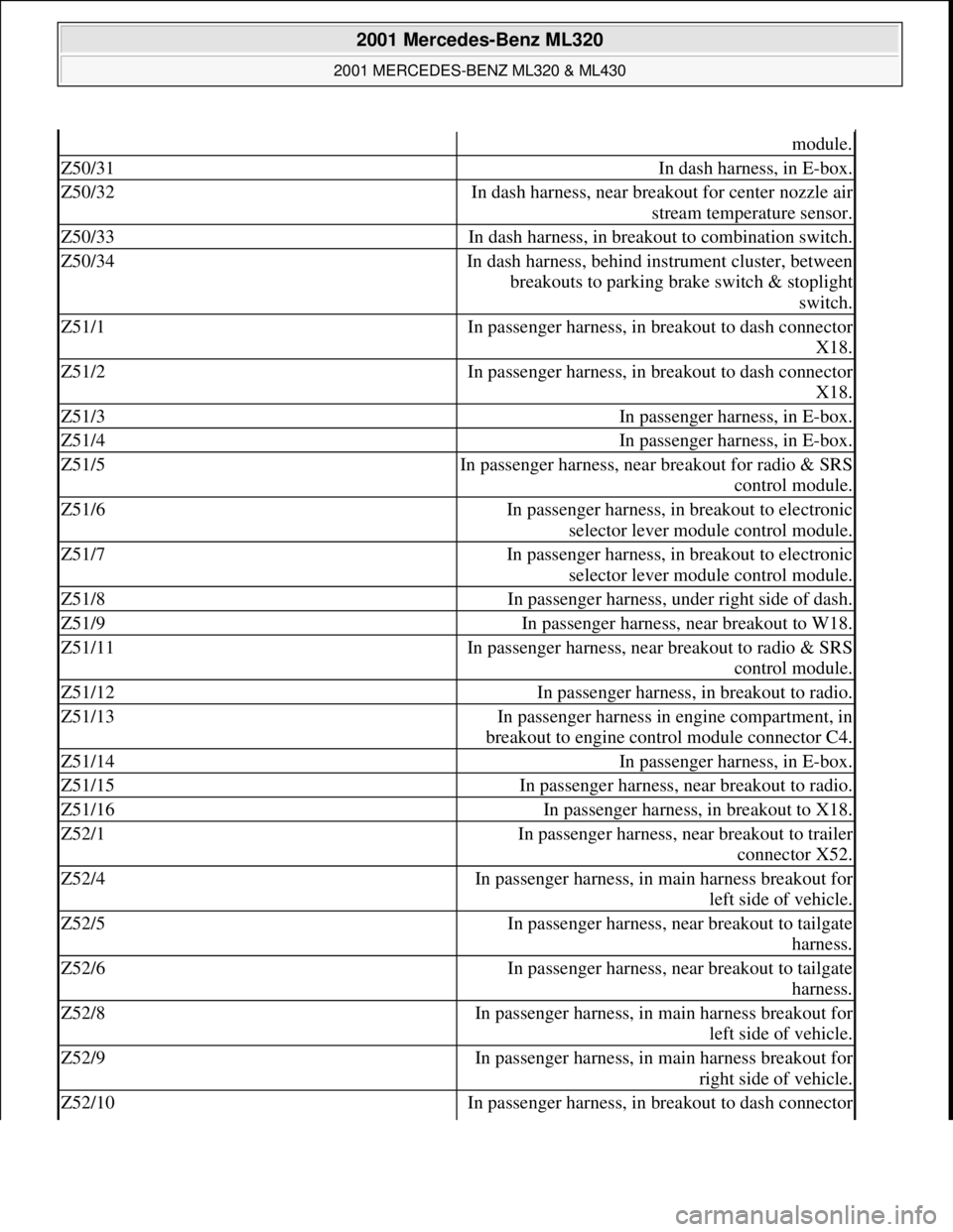
Z50/31In dash harness, in E-box.
Z50/32In dash harness, near breakout for center nozzle air
stream temperature sensor.
Z50/33In dash harness, in breakout to combination switch.
Z50/34In dash harness, behind instrument cluster, between
breakouts to parking brake switch & stoplight
switch.
Z51/1In passenger harness, in breakout to dash connector
X18.
Z51/2In passenger harness, in breakout to dash connector
X18.
Z51/3In passenger harness, in E-box.
Z51/4In passenger harness, in E-box.
Z51/5In passenger harness, near breakout for radio & SRS
control module.
Z51/6In passenger harness, in breakout to electronic
selector lever module control module.
Z51/7In passenger harness, in breakout to electronic
selector lever module control module.
Z51/8In passenger harness, under right side of dash.
Z51/9In passenger harness, near breakout to W18.
Z51/11In passenger harness, near breakout to radio & SRS
control module.
Z51/12In passenger harness, in breakout to radio.
Z51/13In passenger harness in engine compartment, in
breakout to engine control module connector C4.
Z51/14In passenger harness, in E-box.
Z51/15In passenger harness, near breakout to radio.
Z51/16In passenger harness, in breakout to X18.
Z52/1In passenger harness, near breakout to trailer
connector X52.
Z52/4In passenger harness, in main harness breakout for
left side of vehicle.
Z52/5In passenger harness, near breakout to tailgate
harness.
Z52/6In passenger harness, near breakout to tailgate
harness.
Z52/8In passenger harness, in main harness breakout for
left side of vehicle.
Z52/9In passenger harness, in main harness breakout for
right side of vehicle.
Z52/10In passenger harness, in breakout to dash connector
2001 Mercedes-Benz ML320
2001 MERCEDES-BENZ ML320 & ML430
me
Saturday, October 02, 2010 3:21:17 PMPage 10 © 2006 Mitchell Repair Information Company, LLC.
Page 2156 of 4133
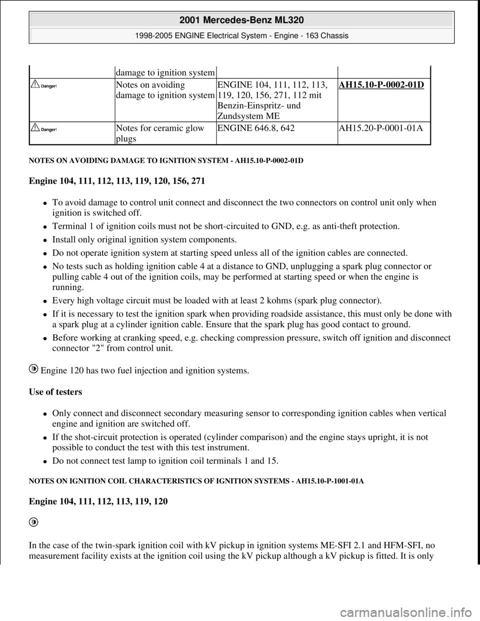
NOTES ON AVOIDING DAMAGE TO IGNITION SYSTEM - AH15.10-P-0002-01D
Engine 104, 111, 112, 113, 119, 120, 156, 271
To avoid damage to control unit connect and disconnect the two connectors on control unit only when
ignition is switched off.
Terminal 1 of ignition coils must not be short-circuited to GND, e.g. as anti-theft protection.
Install only original ignition system components.
Do not operate ignition system at starting speed unless all of the ignition cables are connected.
No tests such as holding ignition cable 4 at a distance to GND, unplugging a spark plug connector or
pulling cable 4 out of the ignition coils, may be performed at starting speed or when the engine is
running.
Every high voltage circuit must be loaded with at least 2 kohms (spark plug connector).
If it is necessary to test the ignition spark when providing roadside assistance, this must only be done with
a spark plug at a cylinder ignition cable. Ensure that the spark plug has good contact to ground.
Before working at cranking speed, e.g. checking compression pressure, switch off ignition and disconnect
connector "2" from control unit.
Engine 120 has two fuel injection and ignition systems.
Use of testers
Only connect and disconnect secondary measuring sensor to corresponding ignition cables when vertical
engine and ignition are switched off.
If the shot-circuit protection is operated (cylinder comparison) and the engine stays upright, it is not
possible to conduct the test with this test instrument.
Do not connect test lamp to ignition coil terminals 1 and 15.
NOTES ON IGNITION COIL CHARACTERISTICS OF IGNITION SYSTEMS - AH15.10-P-1001-01A
Engine 104, 111, 112, 113, 119, 120
In the case of the twin-spark ignition coil with kV pickup in ignition systems ME-SFI 2.1 and HFM-SFI, no
measurement facilit
y exists at the ignition coil using the kV pickup although a kV pickup is fitted. It is only
damage to ignition system
Notes on avoiding
damage to ignition systemENGINE 104, 111, 112, 113,
119, 120, 156, 271, 112 mit
Benzin-Einspritz- und
Zundsystem MEAH15.10-P-0002-01D
Notes for ceramic glow
plugsENGINE 646.8, 642AH15.20-P-0001-01A
2001 Mercedes-Benz ML320
1998-2005 ENGINE Electrical System - Engine - 163 Chassis
me
Saturday, October 02, 2010 3:18:54 PMPage 2 © 2006 Mitchell Repair Information Company, LLC.
Page 2170 of 4133
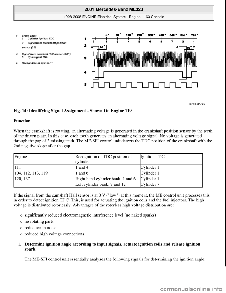
Fig. 14: Identifying Signal Assignment - Shown On Engine 119
Function
When the crankshaft is rotating, an alternating voltage is generated in the crankshaft position sensor by the teeth
of the driven plate. In this case, each tooth generates an alternating voltage signal. No voltage is generated
through the gap of 2 missing teeth. The ME-SFI control unit detects the TDC position of the crankshaft with the
2nd negative slope after the gap.
If the signal from the camshaft Hall sensor is at 0 V ("low") at this moment, the ME control unit processes this
in order to detect ignition TDC. This, is used for actuating the ignition coils and the fuel injectors. The high
voltage is distributed rotorlessly. Advantages of the rotorless high voltage distribution are:
significantly reduced electromagnetic interference level (no naked sparks)
no rotating parts
reduction in noise
reduced high voltage connections.
1.Determine ignition angle according to input signals, actuate ignition coils and release ignition
spark.
The ME-SFI control unit essentially analyzes the following signals for determining the ignition angle:
EngineRecognition of TDC position of
cylinderIgnition TDC
1111 and 4Cylinder 1
104, 112, 113, 1191 and 6Cylinder 1
120, 137Right hand cylinder bank: 1 and 6Cylinder 1
Left cylinder bank: 7 and 12Cylinder 7
2001 Mercedes-Benz ML320
1998-2005 ENGINE Electrical System - Engine - 163 Chassis
me
Saturday, October 02, 2010 3:18:54 PMPage 16 © 2006 Mitchell Repair Information Company, LLC.
Page 2171 of 4133
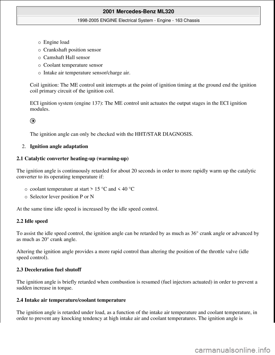
Engine load
Crankshaft position sensor
Camshaft Hall sensor
Coolant temperature sensor
Intake air temperature sensor/charge air.
Coil ignition: The ME control unit interrupts at the point of ignition timing at the ground end the ignition
coil primary circuit of the ignition coil.
ECI ignition system (engine 137): The ME control unit actuates the output stages in the ECI ignition
modules.
The ignition angle can only be checked with the HHT/STAR DIAGNOSIS.
2.Ignition angle adaptation
2.1 Catalytic converter heating-up (warming-up)
The ignition angle is continuously retarded for about 20 seconds in order to more rapidly warm up the catalytic
converter to its operating temperature if:
coolant temperature at start > 15 °C and < 40 °C
Selector lever position P or N
At the same time idle speed is increased by the idle speed control.
2.2 Idle speed
To assist the idle speed control, the ignition angle can be retarded by as much as 36° crank angle or advanced by
as much as 20° crank angle.
Altering the ignition angle provides a more rapid control than altering the position of the throttle valve (idle
speed control).
2.3 Deceleration fuel shutoff
The ignition angle is briefly retarded when combustion is resumed (fuel injectors actuated) in order to prevent a
sudden increase in torque.
2.4 Intake air temperature/coolant temperature
The ignition angle is retarded under load, as a function of the intake air temperature and coolant temperature, in
order to prevent an
y knocking tendency at high intake air and coolant temperatures. The ignition angle is
2001 Mercedes-Benz ML320
1998-2005 ENGINE Electrical System - Engine - 163 Chassis
me
Saturday, October 02, 2010 3:18:54 PMPage 17 © 2006 Mitchell Repair Information Company, LLC.
Page 2172 of 4133
"Retarded" if:
Intake air temperature > 35 °C
Coolant temperature > 105 °C
In supercharged engines the charge air temperature is used as information for the ignition timing adjustment in
place of the intake air temperature.
The values of the retardation of the ignition angle of intake air temperature and coolant temperature are added
together.
2.5 Transmission overload protection
In order to protect the shift elements of the automatic transmission during power shifts (1-2-1, 2-3-2) from
excessive thermal stresses, the ignition angle is briefly retarded during the gearshift and the engine torque
reduced as a result. The ME-SFI control units are supplied with a signal for this purpose from the ETC control
unit (N15/3) over the CAN databus.
2.6 ESP/ASR control mode
In order to reduce the engine torque as rapidly as possible in the ESP/ ASR control mode, the ignition angle is
retarded by the throttle valve actuator (opening angle reduced) prior to the control mode being activated. The
information from the ESP/ASR control unit is supplied over the CAN databus to the ME-SFI control unit.
2.7 Anti-knock control (AKC)
If uncontrolled combustion (knocking) occurs at one or several cylinders, the ignition angle at the relevant
cylinder or cylinders is "Retarded".
2.8 Smooth engine running analysis
To restrain the three way catalytic converter from thermal overload through combustion misfiring and in order
to keep the exhaust emission values, the smooth operation of the engine is continuously monitored.
If combustion misfiring is identified at one or several cylinders, the corresponding fuel injection valves are no
longer actuated after a certain number of misfires.
Engine 104, 111, 112, 113, 119, 120: Smooth operation evaluation is performed through the signals of the
crankshaft position sensor.
Engine 137: Identification of combustion misfiring by means of ionic current signal, see ECI ignition system
function.
2.9 Double ignition engine 112,113,137
2001 Mercedes-Benz ML320
1998-2005 ENGINE Electrical System - Engine - 163 Chassis
me
Saturday, October 02, 2010 3:18:54 PMPage 18 © 2006 Mitchell Repair Information Company, LLC.
Page 2173 of 4133
Two spark plugs for each cylinder are beneficial because of the arrangement of the valves for achieving optimal
emission levels and smooth engine running.
Each spark plug is actuated separately by the ME-SFI control unit through its own ignition coil. On engine 112,
113 both ignition coils of a cylinder are combined to form a dual ignition coil.
In the lower part load range up to approx. 2000 rpm both ignition sparks of a cylinder are triggered
simultaneously. At moderate and high engine loads, the ignition sparks are triggered offset by as much as 10°
crank angle. In this case, the sequence of actuation is constantly varied in order to achieve a uniform wear of
both spark plugs and to avoid deposits on only one side of the combustion chamber.
For troubleshooting in the dual ignition system, it is possible to switch off one ignition circuit each with HHT or
STAR DIAGNOSIS.
ME-SFI ignition system function
diagramEngine 104GF15.12-P-0001-01D
Engine 111GF15.12-P-0001-01G
Engine 112GF15.12-P-0001-01A
Engine 113GF15.12-P-0001-01B
Engine 119GF15.12-P-0001-01E
Engine 120GF15.12-P-0001-01F
ME-SFI control unit
position/task/design/ function GF07.61-P-5000F
ECI ignition system functionEngine 137GF15.15-P-3000L
Ignition coils,
location/task/design/functionEngine 119, 120GF15.10-P-3102F
Engine 104, 111GF15.10-P-3102G
Engine 112, 113GF15.10-P-3102A
Crankshaft position sensor,
location/task/ design/function GF07.04-P-4116F
Camshaft Hall sensor,
location/task/design/ function GF07.04-P-4117F
Spark plugs,
location/task/design/function GF15.10-P-3101F
Intake air temperature sensor,
location/task/ design/function GF07.04-P-2100F
Hot film mass air flow sensor,
location/task/ design/functionEngine 119, 120 (round
connector)GF07.07-P-4118E
Engine 104, 111, 112,
113, 137GF07.07-P-4118G
Coolant temperature sensor,
location/task/ design/functionEngine 104, 111GF07.04-P-5026G
Engine 112, 113, 137GF07.04-P-5026A
Engine 119, 120GF07.04-P-5026F
Electronic accelerator, Engine 104, 111, 112, GF30.20-P-3010E
2001 Mercedes-Benz ML320
1998-2005 ENGINE Electrical System - Engine - 163 Chassis
me
Saturday, October 02, 2010 3:18:54 PMPage 19 © 2006 Mitchell Repair Information Company, LLC.
Page 2176 of 4133
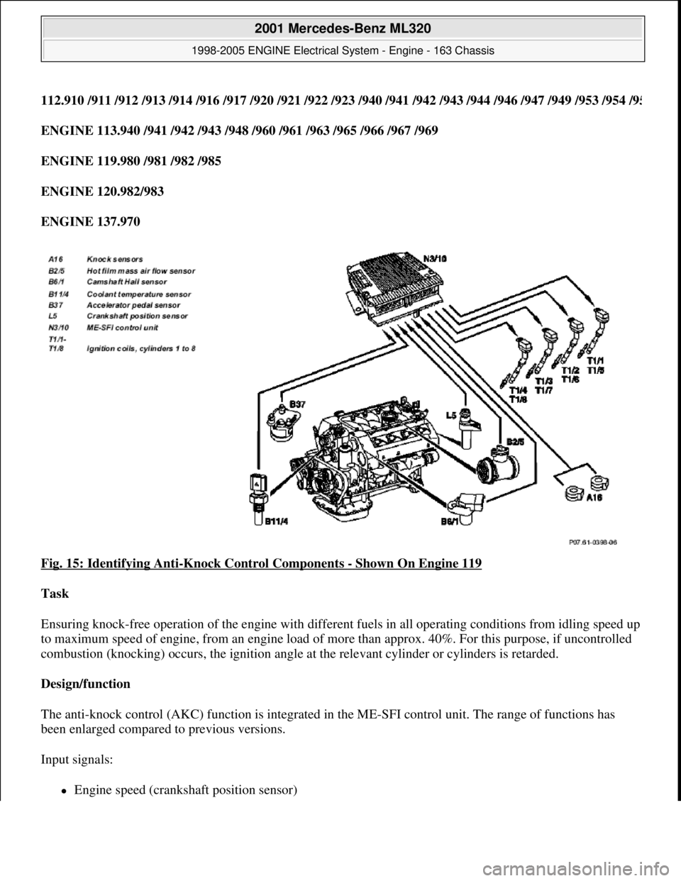
112.910 /911 /912 /913 /914 /916 /917 /920 /921 /922 /923 /940 /941 /942 /943 /944 /946 /947 /949 /953 /954 /95
ENGINE 113.940 /941 /942 /943 /948 /960 /961 /963 /965 /966 /967 /969
ENGINE 119.980 /981 /982 /985
ENGINE 120.982/983
ENGINE 137.970
Fig. 15: Identifying Anti
-Knock Control Components - Shown On Engine 119
Task
Ensuring knock-free operation of the engine with different fuels in all operating conditions from idling speed up
to maximum speed of engine, from an engine load of more than approx. 40%. For this purpose, if uncontrolled
combustion (knocking) occurs, the ignition angle at the relevant cylinder or cylinders is retarded.
Design/function
The anti-knock control (AKC) function is integrated in the ME-SFI control unit. The range of functions has
been enlarged compared to previous versions.
Input signals:
Engine speed (crankshaft position sensor)
2001 Mercedes-Benz ML320
1998-2005 ENGINE Electrical System - Engine - 163 Chassis
me
Saturday, October 02, 2010 3:18:54 PMPage 22 © 2006 Mitchell Repair Information Company, LLC.
Page 2177 of 4133
Camshaft position (camshaft Hall sensor)
Knock identification:
Engine 104, 111, 112, 113, 119, 120 by means of knock sensors Engine 137 by ionic current
measurement
Engine temperature (coolant temperature sensor)
Engine load (hot film air flow sensor or pressure sensor on supercharged engines)
Accelerator pedal position (accelerator pedal sensor)
Precontrol by means of automatic RON switch (internal)
Output signals:
Cylinder specific ignition angle correction on the calculated map value of the ME control unit.
Ignition angle emergency mode if fault identified.
Basic function
The anti-knock control is active from a coolant temperature of 70 °C. If knocking is detected at a cylinder above
an engine load of approx. 40%, its ignition angle is retarded from the next ignition by about 2.3° crank angle
(e.g. M119) or by about 3.0° crank angle (e.g. M120). If knocking continues to be detected, the ignition angle is
continuously retarded in steps of 2.3° crank angle (e.g. M119) until the maximum retardation is reached
(approx. 10 to 15° crank angle, depending on engine speed). In addition, the automatic RON switch influences
the maximum retarding of the ignition timing - the higher the selected RON stage, the less is the maximum
retarding of the ignition timing.
If knocking-free combustion exists, the retardation is reduced in steps of approx. 0.75° crank angle after a few
ignitions (depending on engine speed) until the map value (a) is achieved, or knocking once again occurs.
Adaptation of anti-knock control
The adaptation of the anti-knock control is active from a coolant temperature of approx. 75 °C. Any corrections
required to the ignition angle because of knocking combustion are constantly detected for the specific cylinder
and stored together with the relevant operating state of the engine (engine load/speed range).
The stored adaptation value is taken into account in the output of the individual cylinder angle so that each
cylinder is immediately operated with the optimal ignition angle.
During abrupt acceleration, no values are stored for about 2 seconds in order to avoid any incorrect adaptation
values.
Faults in the case of knocking detection
If no signals are received from the knock sensors or from the ionic current measurement, the ignition angle of
all the c
ylinders is retarded, for safety reasons, by as much as approx. 11° crank angle depending on engine
2001 Mercedes-Benz ML320
1998-2005 ENGINE Electrical System - Engine - 163 Chassis
me
Saturday, October 02, 2010 3:18:54 PMPage 23 © 2006 Mitchell Repair Information Company, LLC.