1997 MERCEDES-BENZ ML350 sensor
[x] Cancel search: sensorPage 1594 of 4133
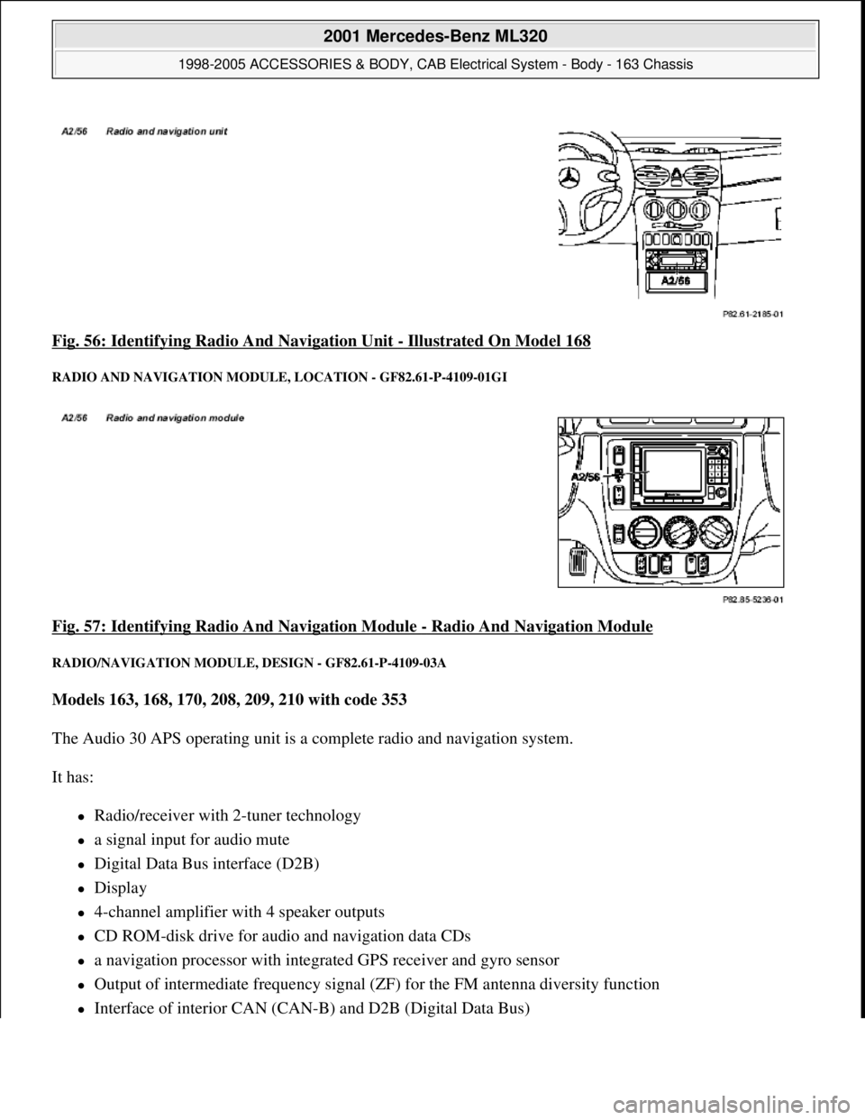
Fig. 56: Identifying Radio And Navigation Unit - Illustrated On Model 168
RADIO AND NAVIGATION MODULE , LOCATION - GF82.61-P-4109-01GI
Fig. 57: Identifying Radio And Navigation Module - Radio And Navigation Module
RADIO/NAVIGATION MODULE , DESIGN - GF82.61-P-4109-03A
Models 163, 168, 170, 208, 209, 210 with code 353
The Audio 30 APS operating unit is a co mplete radio and navigation system.
It has:
Radio/receiver with 2-tuner technology
a signal input for audio mute
Digital Data Bus interface (D2B)
Display
4-channel amplifier with 4 speaker outputs
CD ROM-disk drive for audio and navigation data CDs
a navigation processor with integrated GPS receiver and gyro sensor
Output of intermediate frequency signal (Z F) for the FM antenna diversity function
Interface of interior CAN (CAN-B) and D2B (Digital Data Bus)
2001 Mercedes-Benz ML320
1998-2005 ACCESSORIES & BODY, CAB Electr ical System - Body - 163 Chassis
me
Saturday, October 02, 2010 3:30:05 PMPage 99 © 2006 Mitchell Repair Information Company, LLC.
Page 1595 of 4133
RADIO AND NAVIGATION MODULE, DESIGN - GF82.61-P-4109-03GI
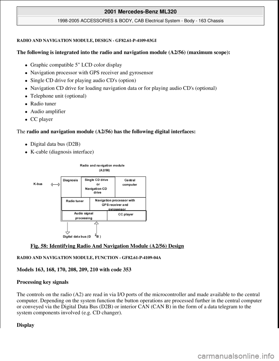
The following is integrated into the radio and navigation module (A2/56) (maximum scope):
Graphic compatible 5" LCD color display
Navigation processor with GPS receiver and gyrosensor
Single CD drive for playing audio CD's (option)
Navigation CD drive for loading navigation data or for playing audio CD's (optional)
Telephone unit (optional)
Radio tuner
Audio amplifier
CC player
The radio and navigation module (A2/56) has the following digital interfaces:
Digital data bus (D2B)
K-cable (diagnosis interface)
Fig. 58: Identifying Radio And Navigation Module (A2/56) Design
RADIO AND NAVIGATION MODULE, FUNCTION - GF82.61-P-4109-04A
Models 163, 168, 170, 208, 209, 210 with code 353
Processing key signals
The controls on the radio (A2) are read in via I/O ports of the microcontroller and made available to the central
computer. Depending on the system function the button operations are processed further in the central computer
or conveyed via the Digital Data Bus (D2B) or interior CAN (CAN B) in the form of a data telegram to the
system components involved (e.g. CD changer).
Display
2001 Mercedes-Benz ML320
1998-2005 ACCESSORIES & BODY, CAB Electrical System - Body - 163 Chassis
me
Saturday, October 02, 2010 3:30:05 PMPage 100 © 2006 Mitchell Repair Information Company, LLC.
Page 1596 of 4133
The display of the radios (A2) has 197 x 32 pixels. Texts are displayed in 3 lines.
After particular functions are called (e.g. navigation), the bottom line shows a variable inscription for the row of
buttons underneath (multifunction buttons). As a result the system can be operated very conveniently with a few
buttons, as the function which is activated when the button is operated, is shown in plain text (e.g. LANG,
ITEM, DYN, CLOCK etc.).
Audio signal output
The audio signals of the various sources (CD, voice output for navigation etc.) are processed by the radio (A2)
and amplified before output by the vehicle speakers.
On models 168, 170, 208 and 210 with the sound system (code 810) the audio signals are finally amplified
by the amplifier for the sound system (N40/3). For this, the audio source data (low-frequency signals) are
transmitted to the amplifier for the sound system (N40/3) via separate lines.
On models 163 and 209 the final amplification of the audio signal is performed by the sound amplifier
(A2/13). All the data are transmitted via the D2B.
Audio mute
An incoming phone call activates the audio mute function (a separate signal input exists on the radio (A2) for
this). When the audio mute function is activated, the current audio source (e.g. radio) is muted automatically.
Navigation processor, GPS control module and gyrosensor
The navigation processor is the central component of the navigation system.
It is integrated into the radio (A2) and from the incoming signals continuously calculates the location and once
the destination is entered calculates the route for navigation. The GPS receiver is integrated into the navigation
processor. It evaluates the satellite signals and calculates from them the vehicle position in degrees longitude
and latitude. Various GPS antennae are used to receive these signals depending on the vehicle model:
Model 163: telephone and GPS roof antenna (A2/49)
Models 168, 208.3, 210: GPS antenna (A2/49a2)
Models 170, 208.4: GPS rear antenna (A2/23a2)
Model 209: GPS antenna (A2/23)
Reception from at least 3 satellites is necessary for exact GPS position calculation. A free view of the sky is
required for this purpose.
The integrated gyrosensor continuously senses every change in direction of the vehicle. Evaluation of this data
is accomplished by the navigation processor.
Calibration of the gyrosensor is not required.
2001 Mercedes-Benz ML320
1998-2005 ACCESSORIES & BODY, CAB Electrical System - Body - 163 Chassis
me
Saturday, October 02, 2010 3:30:05 PMPage 101 © 2006 Mitchell Repair Information Company, LLC.
Page 1599 of 4133
Map data.
The digitized map area on the CD-ROM contains towns, cities, streets, intersections and their attributes (e.g.:
one-way streets, turn prohibitions, ...). It does not contain information about company and private ground,
farms, housing estates and agricultural roads.
Gyrosensor
The gyrosensor determines the direction change of the vehicle. It is installed in the navigation processor .
Calibration is not required.
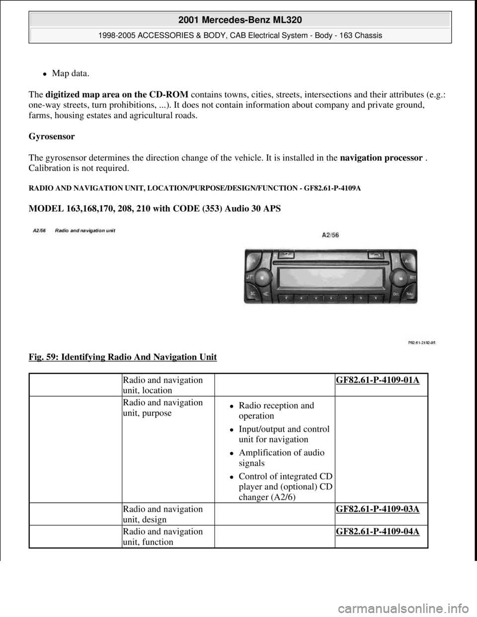
RADIO AND NAVIGATION UNIT, LOCATION/PURPOSE/DESIGN/FUNCTION - GF82.61-P-4109A
MODEL 163,168,170, 208, 210 with CODE (353) Audio 30 APS
Fig. 59: Identifying Radio And Navigation Unit
Radio and navigation
unit, location GF82.61-P-4109-01A
Radio and navigation
unit, purposeRadio reception and
operation
Input/output and control
unit for navigation
Amplification of audio
signals
Control of integrated CD
player and (optional) CD
changer (A2/6)
Radio and navigation
unit, design GF82.61-P-4109-03A
Radio and navigation
unit, function GF82.61-P-4109-04A
2001 Mercedes-Benz ML320
1998-2005 ACCESSORIES & BODY, CAB Electrical System - Body - 163 Chassis
me
Saturday, October 02, 2010 3:30:05 PMPage 104 © 2006 Mitchell Repair Information Company, LLC.
Page 1710 of 4133
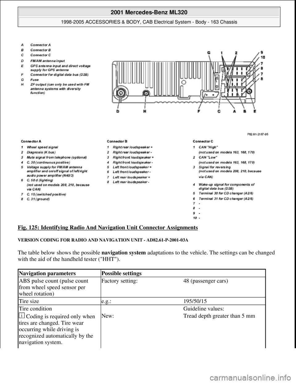
Fig. 125: Identifying Radio And Navigation Unit Connector Assignments
VERSION CODING FOR RADIO AND NAVIGATION UNIT - AD82.61-P-2001-03A
The table below shows the possible navigation system adaptations to the vehicle. The settings can be changed
with the aid of the handheld tester ("HHT").
Navigation parametersPossible settings
ABS pulse count (pulse count
from wheel speed sensor per
wheel rotation)Factory setting:48 (passenger cars)
Tire sizee.g.:195/50/15
Tire condition Guideline values:
Coding is required only when
tires are changed. Tire wear
occurring while driving is
recognized automatically by the
navigation system.New:Tread depth greater than 5 mm
2001 Mercedes-Benz ML320
1998-2005 ACCESSORIES & BODY, CAB Electrical System - Body - 163 Chassis
me
Saturday, October 02, 2010 3:30:08 PMPage 215 © 2006 Mitchell Repair Information Company, LLC.
Page 1715 of 4133
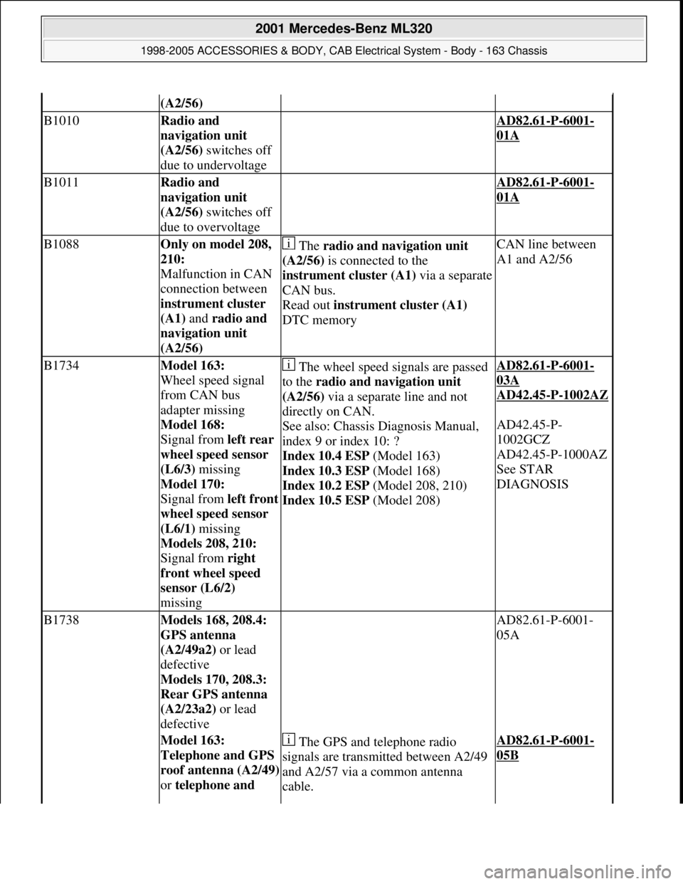
(A2/56)
B1010Radio and
navigation unit
(A2/56) switches off
due to undervoltage AD82.61-P-6001-
01A
B1011Radio and
navigation unit
(A2/56) switches off
due to overvoltage AD82.61-P-6001-
01A
B1088Only on model 208,
210:
Malfunction in CAN
connection between
instrument cluster
(A1) and radio and
navigation unit
(A2/56) The radio and navigation unit
(A2/56) is connected to the
instrument cluster (A1)via a separate
CAN bus.
Read out instrument cluster (A1)
DTC memoryCAN line between
A1 and A2/56
B1734Model 163:
Wheel speed signal
from CAN bus
adapter missing
Model 168:
Signal from left rear
wheel speed sensor
(L6/3) missing
Model 170:
Signal from left front
wheel speed sensor
(L6/1) missing
Models 208, 210:
Signal from right
front wheel speed
sensor (L6/2)
missing The wheel speed signals are passed
to the radio and navigation unit
(A2/56) via a separate line and not
directly on CAN.
See also: Chassis Diagnosis Manual,
index 9 or index 10: ?
Index 10.4 ESP (Model 163)
Index 10.3 ESP (Model 168)
Index 10.2 ESP (Model 208, 210)
Index 10.5 ESP (Model 208)AD82.61-P-6001-
03A
AD42.45
-P-1002AZ
AD42.45-P-
1002GCZ
AD42.45-P-1000AZ
See STAR
DIAGNOSIS
B1738Models 168, 208.4:
GPS antenna
(A2/49a2) or lead
defective
Models 170, 208.3:
Rear GPS antenna
(A2/23a2) or lead
defective AD82.61-P-6001-
05A
Model 163:
Telephone and GPS
roof antenna (A2/49)
or telephone and The GPS and telephone radio
signals are transmitted between A2/49
and A2/57 via a common antenna
cable.AD82.61-P-6001-
05B
2001 Mercedes-Benz ML320
1998-2005 ACCESSORIES & BODY, CAB Electrical System - Body - 163 Chassis
me
Saturday, October 02, 2010 3:30:08 PMPage 220 © 2006 Mitchell Repair Information Company, LLC.
Page 1716 of 4133
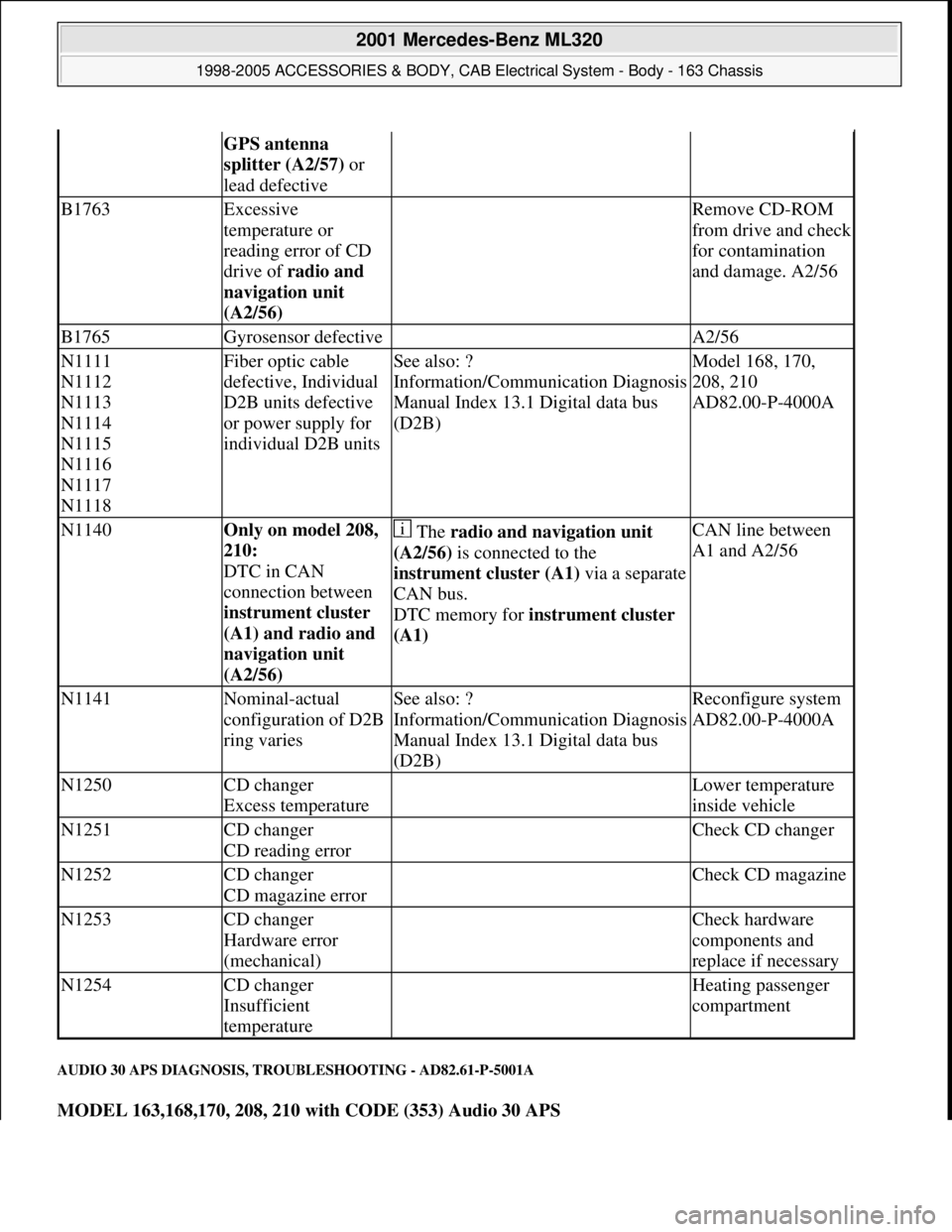
AUDIO 30 APS DIAGNOSIS, TROUBLESHOOTING - AD82.61-P-5001A
MODEL 163,168,170, 208, 210 with CODE (353) Audio 30 APS
GPS antenna
splitter (A2/57) or
lead defective
B1763Excessive
temperature or
reading error of CD
drive of radio and
navigation unit
(A2/56) Remove CD-ROM
from drive and check
for contamination
and damage. A2/56
B1765Gyrosensor defective A2/56
N1111
N1112
N1113
N1114
N1115
N1116
N1117
N1118Fiber optic cable
defective, Individual
D2B units defective
or power supply for
individual D2B unitsSee also: ?
Information/Communication Diagnosis
Manual Index 13.1 Digital data bus
(D2B)Model 168, 170,
208, 210
AD82.00-P-4000A
N1140Only on model 208,
210:
DTC in CAN
connection between
instrument cluster
(A1) and radio and
navigation unit
(A2/56) The radio and navigation unit
(A2/56) is connected to the
instrument cluster (A1)via a separate
CAN bus.
DTC memory for instrument cluster
(A1) CAN line between
A1 and A2/56
N1141Nominal-actual
configuration of D2B
ring variesSee also: ?
Information/Communication Diagnosis
Manual Index 13.1 Digital data bus
(D2B)Reconfigure system
AD82.00-P-4000A
N1250CD changer
Excess temperature Lower temperature
inside vehicle
N1251CD changer
CD reading error Check CD changer
N1252CD changer
CD magazine error Check CD magazine
N1253CD changer
Hardware error
(mechanical) Check hardware
components and
replace if necessary
N1254CD changer
Insufficient
temperature Heating passenger
compartment
2001 Mercedes-Benz ML320
1998-2005 ACCESSORIES & BODY, CAB Electrical System - Body - 163 Chassis
me
Saturday, October 02, 2010 3:30:08 PMPage 221 © 2006 Mitchell Repair Information Company, LLC.
Page 1746 of 4133
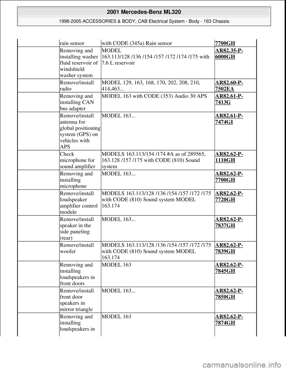
rain sensorwith CODE (345a) Rain sensor7700GH
Removing and
installing washer
fluid reservoir of
windshield
washer systemMODEL
163.113/128 /136 /154 /157 /172 /174 /175 with
7.6 L reservoirAR82.35-P-
6000GH
Remove/install
radioMODEL 129, 163, 168, 170, 202, 208, 210,
414,463...AR82.60-P-
7502EA
Removing and
installing CAN
bus adapterMODEL 163 with CODE (353) Audio 30 APSAR82.61-P-
7413G
Remove/install
antenna for
global positioning
system (GPS) on
vehicles with
APSMODEL 163...AR82.61-P-
7474GI
Check
microphone for
sound amplifierMODELS 163.113/154 /174 #A as of 289565,
163.128 /157 /175 with CODE (810) Sound
systemAR82.62-P-
1110GH
Removing and
installing
microphoneMODEL 163...AR82.62-P-
7700GH
Remove/install
loudspeaker
amplifier control
moduleMODELS 163.113/128 /136 /154 /157 /172 /175
with CODE (810) Sound system MODEL
163.174AR82.62-P-
7720GH
Remove/install
speaker in the
side paneling
(rear)MODEL 163...AR82.62-P-
7837GH
Remove/install
wooferMODELS 163.113/128 /136 /154 /157 /172 /175
with CODE (810) Sound system MODEL
163.174AR82.62-P-
7839GH
Removing and
installing
loudspeakers in
front doorsMODEL 163AR82.62-P-
7845GH
Remove/install
front door
speakers in
mirror triangleMODEL 163...AR82.62-P-
7850GH
Removing and
installing
loudspeakers in MODEL 163AR82.62-P-
7874GH
2001 Mercedes-Benz ML320
1998-2005 ACCESSORIES & BODY, CAB Electrical System - Body - 163 Chassis
me
Saturday, October 02, 2010 3:30:08 PMPage 251 © 2006 Mitchell Repair Information Company, LLC.