Page 1446 of 4133

Task
The ETC control module (N15/3) determines the instantaneous operating condition of the vehicle and controls
all gearshift sequences taking into account the ease of shifting and the driving situation. This involves receiving,
converting and transmitting various digital and analog signals. See Fig. 157
.
It receives operating data in the form of input signals from:
Starter Lock-Out Contact (Y3/6S1)
RPM Sensor 2 (Y3/6N2)
RPM Sensor 3 (Y3/6N3)
Transmission Oil Temperature Sensor (Y3/6B1)
In addition there is a connection via the engine compartment bus to the:
Instrument Cluster (A1)
ME-SFI Control Module (N3/10) or CDI Control Module (N3/9)
The solenoid valves for the modulating and shift pressure and for the gear changes are actuated by the ETC
control module (N15/3).
The pressure required is calculated from all input signals, adjusted to the torque to be transferred. The following
information from other systems is then processed:
ME-SFI Control Module (N3/10) or CDI Control Module (N3/9):
Engine Torque
Engine Speed
Accelerator Pedal Position
Gear Shift
Engine Status
Electronic selector lever module control module (N15/5):
Kickdown Switch (S16/6)
Selector Lever Position P/N
Traction system control module (N47):
Transmission Ratio
Speeds
Instrument cluster (A1):
2001 Mercedes-Benz ML320
1998-03 AUTOMATIC TRANSMISSIONS Complete Transmissions - ML 320 - 722.662
me
Saturday, October 02, 2010 3:15:29 PMPage 277 © 2006 Mitchell Repair Information Company, LLC.
Page 1449 of 4133

The ETC control module (N15/3) determines the instantaneous operating condition of the vehicle and controls
all gearshift sequences taking into account the ease of shifting and the driving situation. See Fig. 158
. This
involves receiving , converting and transmitting various digital and analog signals.
Input Signals:
Starter Lock-Out Contact (Y3/6S1)
RPM Sensor 2 (Y3/6N2)
RPM Sensor 3 (Y3/6N3)
Transmission Oil Temperature Sensor (Y3/6B1)
Kickdown Switch (S16/6)
Gear Recognition Switch (S16/10)
Output signals:
Reverse/Parking Lock Valve
Input And Output Signals:
Datalink Connector (X11/4)
In addition there is a connection via the engine compartment bus to the:
ME-SFI Control Module (N3/10) or CDI Control Module (N3/9)
Traction System Control Module (N47)
Transfer Case Control Module (N78)
The solenoid valves for the modulating and shift pressure and for the gear changes are actuated by the ETC
control module (N15/3). The pressure required is calculated from all input signals, adjusted to the torque to be
transferred.
The following information from other systems is then processed:
ME-SFI Control Module (N3/10) or CDI Control Module (N3/9)
Reverse And Parking Lock Solenoids (Y66/1)
Selector Lever Position (P/N) to the Engine Control Module (ME-SFI) (N3/10) (only on detection of the
selector lever position "P" or "N" on the transmission range recognition switch (S16/10) and at the starter
interlock contact (Y3/6s1)).
Traction System Control Module (N47):
Wheel Speeds
Gear Shift
Traction Status
2001 Mercedes-Benz ML320
1998-03 AUTOMATIC TRANSMISSIONS Complete Transmissions - ML 320 - 722.662
me
Saturday, October 02, 2010 3:15:29 PMPage 280 © 2006 Mitchell Repair Information Company, LLC.
Page 1455 of 4133
See KICKDOWN SWITCH, LOCATION/TASK/DESIGN/FUNCTION MODEL 163 WITHOUT
TOUCH SHIFT.
Starter Lock-Out Contact, Location/Task/Design/Function
See STARTER LOCK
-OUT CONTACT, LOCATION/TASK/DESIGN/FUNCTION.
Temperature Sensor, Location/Task/Design/Function
See TEMPERATURE SENSOR, LOCATION/TASK/DESIGN/FUNCTION
.
Wheel Speed Sensor, Location/Task/Function
See WHEEL SPEED SENSOR, LOCATION/TASK/FUNCTION
.
Location/Task/Design/Function Of Oil Pump
See LOCATION/TASK/DESIGN/FUNCTION OF OIL PUMP
.
Kickdown Switch, Location/Task/Design/Function Model 163 Without Touch Shift
2001 Mercedes-Benz ML320
1998-03 AUTOMATIC TRANSMISSIONS Complete Transmissions - ML 320 - 722.662
me
Saturday, October 02, 2010 3:15:29 PMPage 286 © 2006 Mitchell Repair Information Company, LLC.
Page 1486 of 4133
Via the selector scheme symbols (87) the alternative selector lever positions and their sequence are shown
symbolically.
Speed Sensor, Function
2001 Mercedes-Benz ML320
1998-03 AUTOMATIC TRANSMISSIONS Complete Transmissions - ML 320 - 722.662
me
Saturday, October 02, 2010 3:15:30 PMPage 317 © 2006 Mitchell Repair Information Company, LLC.
Page 1487 of 4133
Fig. 179: Speed Sensor, Function
Courtesy of MERCEDES-BENZ OF NORTH AMERICA.
2001 Mercedes-Benz ML320
1998-03 AUTOMATIC TRANSMI SSIONS Complete Transmissions - ML 320 - 722.662
me
Saturday, October 02, 2010 3:15:30 PMPage 318 © 2006 Mitchell Repair Information Company, LLC.
Page 1488 of 4133
Operation
The RPM sensors are pressed against the transmission housing (51) by a spring (49) which is held against the
valve housing of the shift plate (2a). See .Fig. 179
This ensures a defined distance between the RPM sensors
and the exciter ring (50). RPM sensor 2 (Y3/6yn2) records the speed of the front planetary gear carrier via the
inner multiple-disc carrier of the front multiple-disc clutch (K1c).
2001 Mercedes-Benz ML320
1998-03 AUTOMATIC TRANSMISSIONS Complete Transmissions - ML 320 - 722.662
me
Saturday, October 02, 2010 3:15:30 PMPage 319 © 2006 Mitchell Repair Information Company, LLC.
Page 1512 of 4133

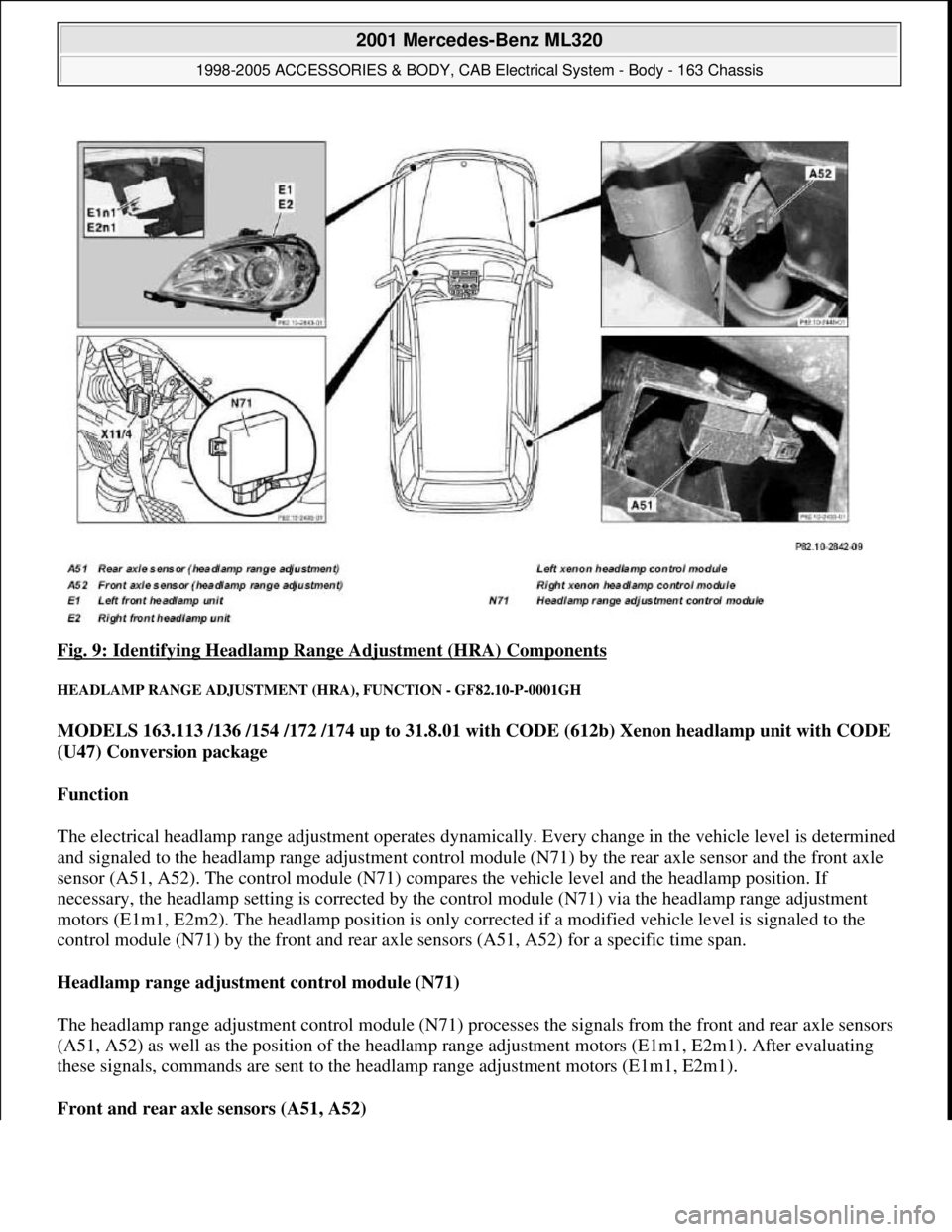
Fig. 9: Identifying Headlamp Range Adjustment (HRA) Components
HEADLAMP RANGE ADJUSTMENT (HRA), FUNCTION - GF82.10-P-0001GH
MODELS 163.113 /136 /154 /172 /174 up to 31.8.01 with CODE (612b) Xenon headlamp unit with CODE
(U47) Conversion package
Function
The electrical headlamp range adjustment operates dynamically. Every change in the vehicle level is determined
and signaled to the headlamp range adjustment control module (N71) by the rear axle sensor and the front axle
sensor (A51, A52). The control module (N71) compares the vehicle level and the headlamp position. If
necessary, the headlamp setting is corrected by the control module (N71) via the headlamp range adjustment
motors (E1m1, E2m2). The headlamp position is only corrected if a modified vehicle level is signaled to the
control module (N71) by the front and rear axle sensors (A51, A52) for a specific time span.
Headlamp range adjustment control module (N71)
The headlamp range adjustment control module (N71) processes the signals from the front and rear axle sensors
(A51, A52) as well as the position of the headlamp range adjustment motors (E1m1, E2m1). After evaluating
these signals, commands are sent to the headlamp range adjustment motors (E1m1, E2m1).
Front and rear axle sensors (A51, A52)
2001 Mercedes-Benz ML320
1998-2005 ACCESSORIES & BODY, CAB Electrical System - Body - 163 Chassis
me
Saturday, October 02, 2010 3:30:04 PMPage 17 © 2006 Mitchell Repair Information Company, LLC.
Page 1513 of 4133

A sensor is fitted to the front axle and to the rear axle and the sensors pick up the instantaneous vehicle level at
the control arm. These sensors (A51, A52) transmit the determined vehicle level to the control module (N71).
Headlamp range adjustment motor (E1m1, E2m1)
The position of the reflectors is signaled to the headlamp range adjustment control module (N71) by a
potentiometer in the headlamp range adjustment motor. The motors (E1 m1, E2m1) receive a command from
the control module (N71) for correcting the headlamp position. If the low beam is switched on and the key is in
position 2, the motors are referenced. The reflectors are moved to the lowest position and then, depending on
the vehicle level, moved to the correct position.
HEADLAMP RANGE ADJUSTMENT (HRA), FUNCTION - GF82.10-P-0001GHA
MODELS 163.113 /128 /154 /172 /174 as of 1.9.01, 163.157 with CODE (614) Bi-xenon headlamp unit
Function
The electrical headlamp range adjustment operates dynamically. Every change in the vehicle level is determined
and signaled to the headlamp range adjustment control module (N71) by the rear axle sensor and the front axle
sensor (A51, A52). The control module (N71) compares the vehicle level and the headlamp position. If
necessary, the headlamp setting is corrected by the control module (N71) via the headlamp range adjustment
motors (E1m1, E2m2). The headlamp position is only corrected if a modified vehicle level is signaled to the
control module (N71) by the front and rear axle sensors (A51, A52) for a specific time span.
Headlamp range adjustment control module (N71)
The headlamp range adjustment control module (N71) processes the signals from the front and rear axle sensors
(A51, A52) as well as the position of the headlamp range adjustment motors (E1m1, E2m1). After evaluating
these signals, commands are sent to the headlamp range adjustment motors (E1m1, E2m1).
Front and rear axle sensors (A51, A52)
A sensor is fitted to the front axle and to the rear axle and the sensors pick up the instantaneous vehicle level at
the control arm. These sensors (A51, A52) transmit the determined vehicle level to the control module (N71).
Headlamp range adjustment motor (E1m1, E2m1)
The position of the reflectors is signaled to the headlamp range adjustment control module (N71) by a
potentiometer in the headlamp range adjustment motor. The motors (E1 m1, E2m1) receive a command from
the control module (N71) for correcting the headlamp position. If the low beam is switched on and the key is in
position 2, the motors are referenced. The reflectors are moved to the lowest position and then, depending on
the vehicle level, moved to the correct position.
Headlamp range control
(HRC), location of
components GF82.10-P-0001-01GH
2001 Mercedes-Benz ML320
1998-2005 ACCESSORIES & BODY, CAB Electrical System - Body - 163 Chassis
me
Saturday, October 02, 2010 3:30:04 PMPage 18 © 2006 Mitchell Repair Information Company, LLC.