1997 MERCEDES-BENZ ML350 sensor
[x] Cancel search: sensorPage 1542 of 4133
SAFETY SHUTOFF (WSA) - FUNCTION - GF82.30-P-3005GH
MODEL 163 Applicable as of 1.9.00
Safety shutoff
The intermittent wipe function is interrupted when the vehicle comes to a complete stop and at least one of
the front doors is open. Any wipe cycle in progress is completed before wipers come to a halt.
Wiping resumes when both front doors are closed and/or the vehicle is put into motion.
The safety shutoff therefore only operates when the vehicle is at a complete stop. This ensures that the
intermittent wiping feature remains available during driving even if a door jamb switch is defective.
ANTI-LOCK PROTECTION FOR WIPER MOTOR, FUNCTION - GF82.30-P-4008GH
MODEL 163
The all-activity module(AAM) (N10) recognizes that the wiper motor (M6/1) is locked up because of the
absence of signals from the cam switch.
If signals are not recognized for longer than 1 s the front wiper motor relay (F1k17) is no longer actuated.
The anti-lock protection is only effective in the function interval wiping . In other wiper stages the AAM does
not have influence on the wiper motor.
RAIN SENSOR - FUNCTION - GF82.30-P-4103-02GH
location/purpose/design/function4100GH
as of 1.12.99GF54.21-P-
4100GK
Extended activity module,
location/purposeas of 1.12.99GF54.21-P-
4106GH
Windshield Intermittent
Wipe - Function GF82.30-P-3003GH
Wiper motor,
location/purpose/design/function GF82.30-P-
4104GH
All-activity module (AAM),
location/purpose/ design/functionup to 30.11.99GF54.21-P-
4100GH
as of 1.12.99GF54.21-P-
4100GK
2001 Mercedes-Benz ML320
1998-2005 ACCESSORIES & BODY, CAB Electrical System - Body - 163 Chassis
me
Saturday, October 02, 2010 3:30:04 PMPage 47 © 2006 Mitchell Repair Information Company, LLC.
Page 1543 of 4133
How it works
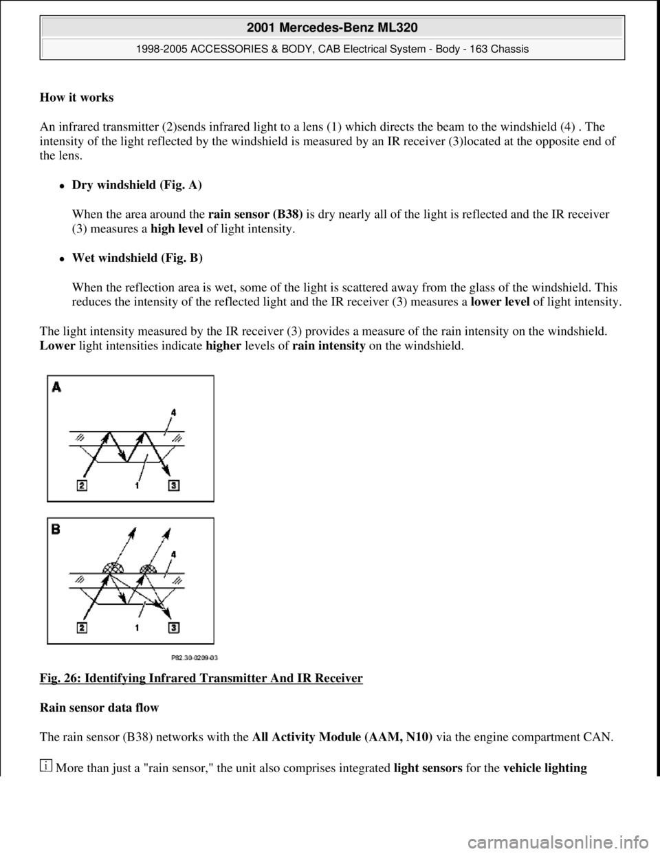
An infrared transmitter (2)sends infrared light to a lens (1) which directs the beam to the windshield (4) . The
intensity of the light reflected by the windshield is measured by an IR receiver (3)located at the opposite end of
the lens.
Dry windshield (Fig. A)
When the area around the rain sensor (B38) is dry nearly all of the light is reflected and the IR receiver
(3) measures a high level of light intensity.
Wet windshield (Fig. B)
When the reflection area is wet, some of the light is scattered away from the glass of the windshield. This
reduces the intensity of the reflected light and the IR receiver (3) measures a lower level of light intensity.
The light intensity measured by the IR receiver (3) provides a measure of the rain intensity on the windshield.
Lower light intensities indicate higher levels of rain intensity on the windshield.
Fig. 26: Identifying Infrared Transmitter And IR Receiver
Rain sensor data flow
The rain sensor (B38) networks with the All Activity Module (AAM, N10) via the engine compartment CAN.
More than
just a "rain sensor," the unit also comprises integrated light sensors for the vehicle lighting
2001 Mercedes-Benz ML320
1998-2005 ACCESSORIES & BODY, CAB Electrical System - Body - 163 Chassis
me
Saturday, October 02, 2010 3:30:04 PMPage 48 © 2006 Mitchell Repair Information Company, LLC.
Page 1544 of 4133
system . Data from the light sensors is also sent to the All Activity Module (AAM, N10) via the engine
compartment CAN.
Power supply
Power is supplied to the rain sensor (B38) via KI. 15 so that these functions are available only when the ignition
is on.
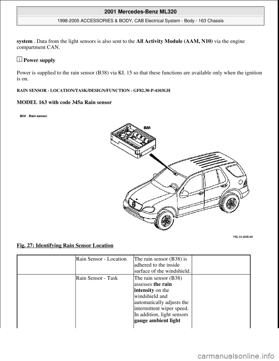
RAIN SENSOR - LOCATION/TASK/DESIGN/FUNCTION - GF82.30-P-4103GH
MODEL 163 with code 345a Rain sensor
Fig. 27: Identifying Rain Sensor Location
Rain Sensor - LocationThe rain sensor (B38) is
adhered to the inside
surface of the windshield.
Rain Sensor - TaskThe rain sensor (B38)
assesses the rain
intensity on the
windshield and
automatically adjusts the
intermittent wiper speed.
In addition, light sensors
gauge ambient light
2001 Mercedes-Benz ML320
1998-2005 ACCESSORIES & BODY, CAB Electrical System - Body - 163 Chassis
me
Saturday, October 02, 2010 3:30:05 PMPage 49 © 2006 Mitchell Repair Information Company, LLC.
Page 1545 of 4133
WIPER MOTOR, FUNCTION - GF82.30-P-4104-01GH
The wiper arm can be driven by the motor with two speeds. The motor runs at high or low speed depending on
brush voltage present.
The cam switch switches circuit 31b from circuit 15 to circuit 31 when the windshield wiper runs through the
park position.
WIPER MOTOR, DESIGN - GF82.30-P-4104-02GH
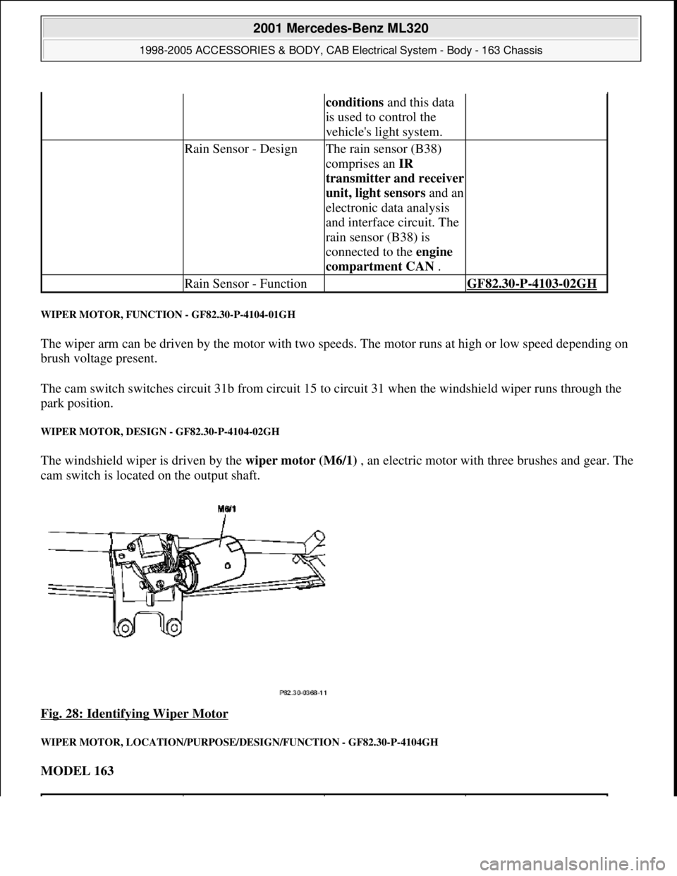
The windshield wiper is driven by the wiper motor (M6/1) , an electric motor with three brushes and gear. The
cam switch is located on the output shaft.
Fig. 28: Identifying Wiper Motor
WIPER MOTOR, LOCATION/PURPOSE/DESIGN/FUNCTION - GF82.30-P-4104GH
MODEL 163
conditions and this data
is used to control the
vehicle's light system.
Rain Sensor - DesignThe rain sensor (B38)
comprises an IR
transmitter and receiver
unit, light sensorsand an
electronic data analysis
and interface circuit. The
rain sensor (B38) is
connected to the engine
compartment CAN .
Rain Sensor - Function GF82.30-P-4103-02GH
2001 Mercedes-Benz ML320
1998-2005 ACCESSORIES & BODY, CAB Electrical System - Body - 163 Chassis
me
Saturday, October 02, 2010 3:30:05 PMPage 50 © 2006 Mitchell Repair Information Company, LLC.
Page 1568 of 4133
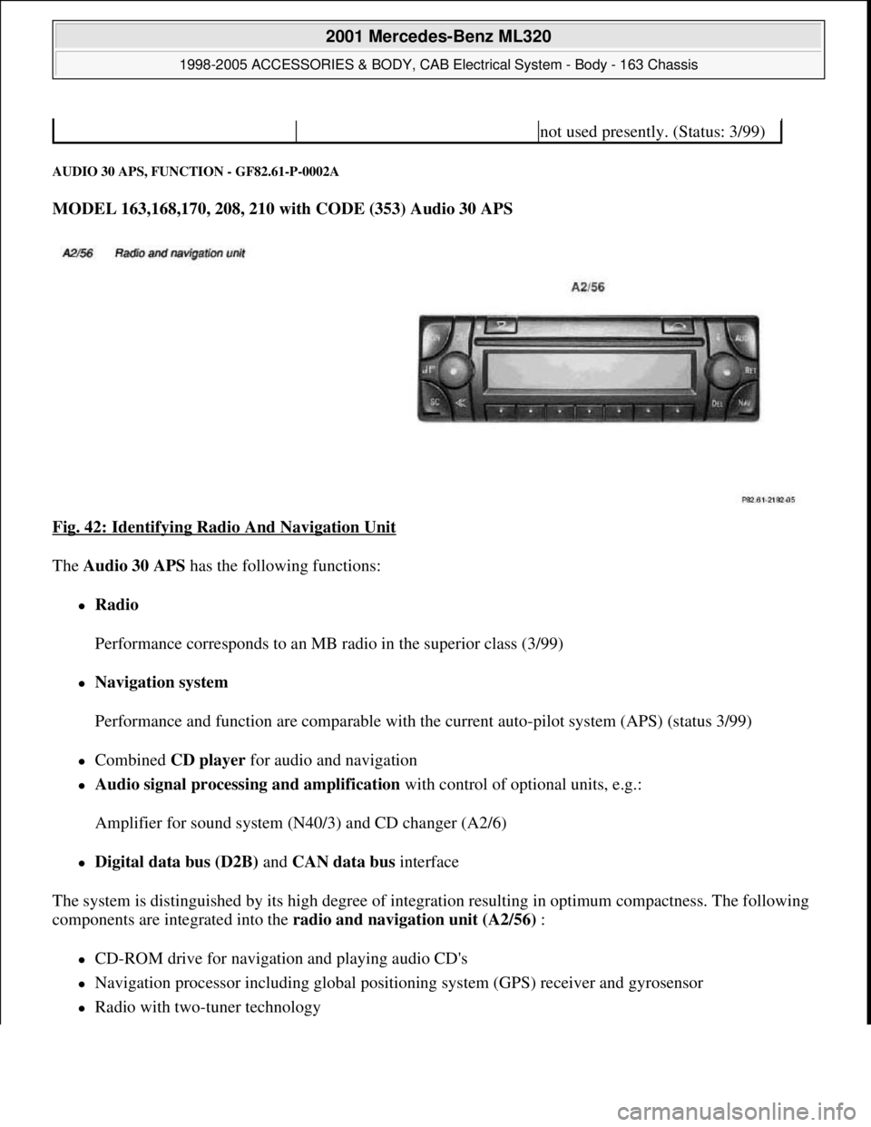
AUDIO 30 APS, FUNCTION - GF82.61-P-0002A
MODEL 163,168,170, 208, 210 with CODE (353) Audio 30 APS
Fig. 42: Identifying Radio And Navigation Unit
The Audio 30 APS has the following functions:
Radio
Performance corresponds to an MB radio in the superior class (3/99)
Navigation system
Performance and function are comparable with the current auto-pilot system (APS) (status 3/99)
Combined CD player for audio and navigation
Audio signal processing and amplification with control of optional units, e.g.:
Amplifier for sound system (N40/3) and CD changer (A2/6)
Digital data bus (D2B) and CAN data bus interface
The system is distinguished by its high degree of integration resulting in optimum compactness. The following
components are integrated into the radio and navigation unit (A2/56) :
CD-ROM drive for navigation and playing audio CD's
Navigation processor including global positioning system (GPS) receiver and gyrosensor
Radio with two-tuner technology
not used presently. (Status: 3/99)
2001 Mercedes-Benz ML320
1998-2005 ACCESSORIES & BODY, CAB Electrical System - Body - 163 Chassis
me
Saturday, October 02, 2010 3:30:05 PMPage 73 © 2006 Mitchell Repair Information Company, LLC.
Page 1575 of 4133
Left rear rpm sensor (L6/3) (model 168)
Wheel speed sensor, left front (L6/1)
Right front rpm sensor (L6/2) (model 208, 210)
Left front rpm sensor (L6/1) and right front rpm sensor (L6/2) (models 203, 209)
The evaluation of the wheel speed signals reveals the mileage covered.
The wheel speed signals of the not driven wheels are evaluated, since their slip between the roadway and tire
is lower, which results in a more accurate result when calculating the mileage.
Calculation of the vehicle orientation
The navigation computer calculates the direction in which the vehicle is traveling (compass direction) from the
data from the gyrosensor and the sequence of locations calculated with the aid of the global positioning system
(GPS). The difference in the calculated mileage and the mileage actually covered between 2 turn-off points is
used to automatically recalibrate the tire circumference (necessary due to tire wear).
Calculation of the direction of motion
The navigation processor recognizes the direction of motion (forward or reverse) from the reverse signal.
Calibration of tire circumference
As a matter of principle, the navigation system recalibrates itself while driving as described. However, this may
require driving a longer distance. After changing tires, manual recalibration should therefore be accomplished.
To do this, it is necessary to enter the tire size (e.g.:195/050/015)and possibly the following information:
new tires (tread depth > approx. 5 mm)
used tires (tread depth < approx. 5 mm)
The entry can be done two different ways:
With aid of STAR DIAGNOSIS.
By calling the "Navigation --> TIRE" menu at the radio (A2)
Errors due to vehicle movement with switched off ignition lead to an inaccurate basic location finding.
Rolling backwards without the reverse gear engaged is evaluated as forwards motion, and may lead to an error
in the location finding. Rolling with the ignition switched off or vehicle transportation also falsify map
matching.
The errors are, however, corrected automatically after a short time by the navigation processor after
receiving GPS data.
A special calibration drive by driving around a defined test path is not ever required.
2001 Mercedes-Benz ML320
1998-2005 ACCESSORIES & BODY, CAB Electrical System - Body - 163 Chassis
me
Saturday, October 02, 2010 3:30:05 PMPage 80 © 2006 Mitchell Repair Information Company, LLC.
Page 1576 of 4133
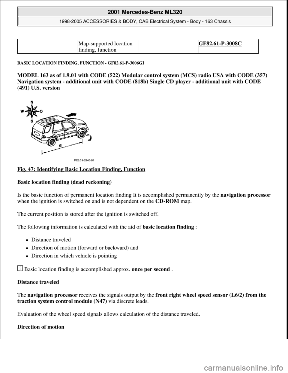
BASIC LOCATION FINDING, FUNCTION - GF82.61-P-3006GI
MODEL 163 as of 1.9.01 with CODE (522) Modular control system (MCS) radio USA with CODE (357)
Navigation system - additional unit with CODE (818b) Single CD player - additional unit with CODE
(491) U.S. version
Fig. 47: Identifying Basic Location Finding, Function
Basic location finding (dead reckoning)
Is the basic function of permanent location finding It is accomplished permanently by the navigation processor
when the ignition is switched on and is not dependent on the CD-ROM map.
The current position is stored after the ignition is switched off.
The following information is calculated with the aid of basic location finding :
Distance traveled
Direction of motion (forward or backward) and
Direction in which vehicle is pointing
Basic location finding is accomplished approx. once per second .
Distance traveled
The navigation processor receives the signals output by the front right wheel speed sensor (L6/2) from the
traction system control module (N47) via discrete leads.
Evaluation of the wheel speed signals allows calculation of the distance traveled.
Direction of motion
Map-supported location
finding, function GF82.61-P-3008C
2001 Mercedes-Benz ML320
1998-2005 ACCESSORIES & BODY, CAB Electrical System - Body - 163 Chassis
me
Saturday, October 02, 2010 3:30:05 PMPage 81 © 2006 Mitchell Repair Information Company, LLC.
Page 1577 of 4133
The navigation processor recognizes the direction of motion (forward or reverse) from the reverse signal.
Direction in which vehicle is pointing
From the data of the gyrosensor and the sequence of the locations calculated with GPS the navigation
processor the calculates the direction in which the vehicle is pointing (compass direction).
The difference between calculated and actual distance traveled between two turning points is used for automatic
recalibration of the tire circumference (required due to tire wear).
Location finding errors during basic location finding
Rolling backwards without the reverse gear engaged is evaluated as forward motion, and may lead to an error in
the location finding.
Rolling with the ignition switched off or vehicle transportation also falsify map matching.
In both cases the deviation is automatically corrected by the navigation processor after receiving GPS data .
Calibration
Wheel calibration is not required following tire change.
GLOBAL POSITIONING SYSTEM LOCATION FINDING, FUNCTION - GF82.61-P-3007C
MODEL 163, 168, 170, 203.0 /2 /7, 208, 209.3 /4, 210 with CODE (353) Audio 30 APS
Basic representation of the GPS location finding shown on model 210
Global positioning system
location finding, function GF82.61-P-3007GI
Map-supported location
finding, function GF82.61-P-3008GI
Guidance, function GF82.61-P-3012GI
Radio and navigation
module, location/purpose/
design/function GF82.61-P-4109GI
2001 Mercedes-Benz ML320
1998-2005 ACCESSORIES & BODY, CAB Electrical System - Body - 163 Chassis
me
Saturday, October 02, 2010 3:30:05 PMPage 82 © 2006 Mitchell Repair Information Company, LLC.