1997 MERCEDES-BENZ ML350 sensor
[x] Cancel search: sensorPage 2494 of 4133
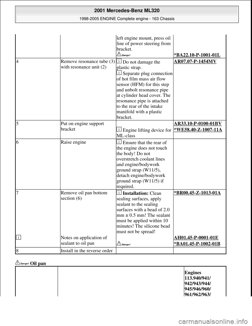
Oil pan
left engine mount, press oil
line of power steering from
bracket.
*BA22.10-P-1001-01L
4Remove resonance tube (3)
with resonance unit (2) Do not damage the
plastic strap.
Separate plug connection
of hot film mass air flow
sensor (HFM) for this step
and unbolt resonance pipe
at cylinder head cover. The
resonance pipe is attached
to the rear of the intake
manifold with a plastic
bracket.AR07.07-P-1454MV
5Put on engine support
bracket AR33.10-P-0100-01BV
Engine lifting device for
ML-class*WE58.40-Z-1007-11A
6Raise engine Ensure that the rear of
the engine does not touch
the body! Do not
overstretch coolant lines
and engine/bodywork
ground strap (W11/5),
detach engine/bodywork
ground strap (W11/5) if
required.
7Remove oil pan bottom
section (6) Installation: Clean
sealing surfaces, apply
sealant to the sealing
surfaces with a bead of 2.0
mm ± 0.5 mm! The sealant
must be applied within 10
minutes! The silicone bead
must not be spread!*BR00.45-Z-1013-01A
Notes on application of
sealant to oil pan AH01.45-P-0001-01E
*BA01.45-P-1002-01B
8Install in the reverse order
Engines
113.940/941/
942/943/944/
945/946/960/
961/962/963/
2001 Mercedes-Benz ML320
1998-2005 ENGINE Complete engine - 163 Chassis
me
Saturday, October 02, 2010 3:17:58 PMPage 138 © 2006 Mitchell Repair Information Company, LLC.
Page 2523 of 4133
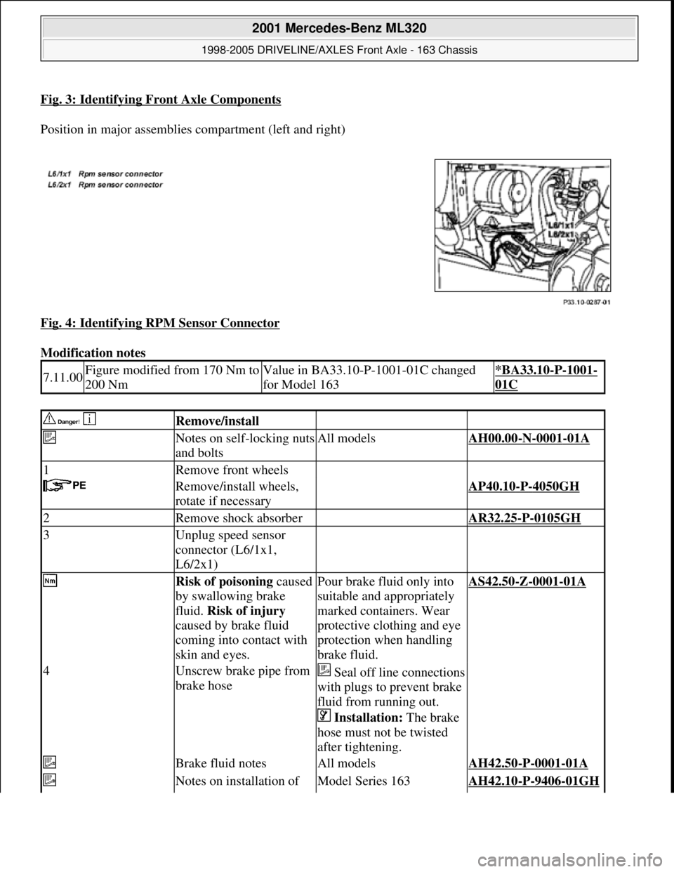
Fig. 3: Identifying Front Axle Components
Position in major assemblies compartment (left and right)
Fig. 4: Identifying RPM Sensor Connector
Modification notes
7.11.00Figure modified from 170 Nm to
200 NmValue in BA33.10-P-1001-01C changed
for Model 163*BA33.10-P-1001-
01C
Remove/install
Notes on self-locking nuts
and boltsAll modelsAH00.00-N-0001-01A
1Remove front wheels
Remove/install wheels,
rotate if necessaryAP40.10-P-4050GH
2Remove shock absorber AR32.25-P-0105GH
3Unplug speed sensor
connector (L6/1x1,
L6/2x1)
Risk of poisoning caused
by swallowing brake
fluid. Risk of injury
caused by brake fluid
coming into contact with
skin and eyes.Pour brake fluid only into
suitable and appropriately
marked containers. Wear
protective clothing and eye
protection when handling
brake fluid.AS42.50-Z-0001-01A
4Unscrew brake pipe from
brake hoseSeal off line connections
with plugs to prevent brake
fluid from running out.
Installation: The brake
hose must not be twisted
after tightening.
Brake fluid notesAll modelsAH42.50-P-0001-01A
Notes on installation of Model Series 163AH42.10-P-9406-01GH
2001 Mercedes-Benz ML320
1998-2005 DRIVELINE/AXLES Front Axle - 163 Chassis
me
Saturday, October 02, 2010 3:38:21 PMPage 4 © 2006 Mitchell Repair Information Company, LLC.
Page 2532 of 4133
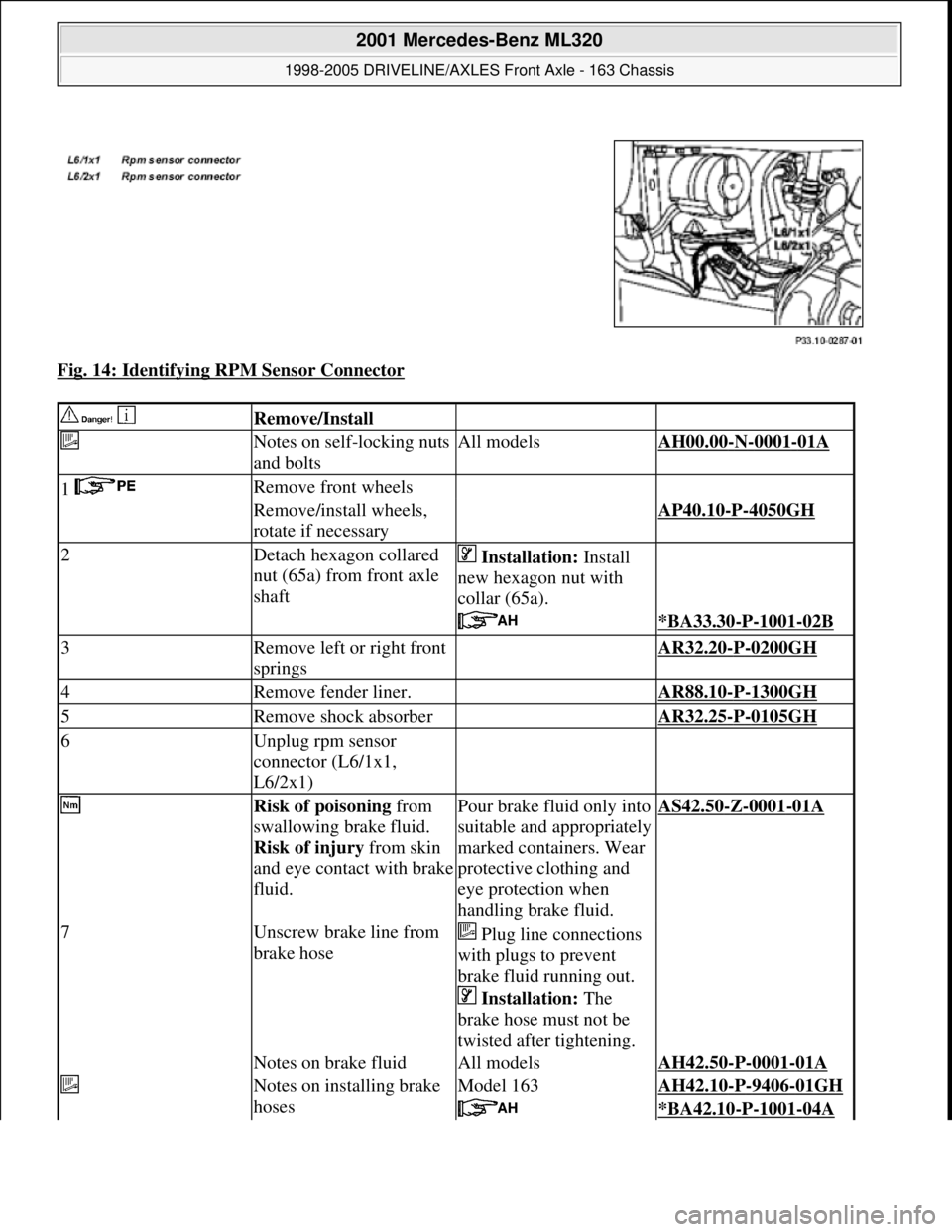
Fig. 14: Identifying RPM Sensor Connector
Remove/Install
Notes on self-locking nuts
and boltsAll modelsAH00.00-N-0001-01A
1 Remove front wheels
Remove/install wheels,
rotate if necessaryAP40.10-P-4050GH
2Detach hexagon collared
nut (65a) from front axle
shaft Installation: Install
new hexagon nut with
collar (65a).
*BA33.30-P-1001-02B
3Remove left or right front
springs AR32.20-P-0200GH
4Remove fender liner. AR88.10-P-1300GH
5Remove shock absorber AR32.25-P-0105GH
6Unplug rpm sensor
connector (L6/1x1,
L6/2x1)
Risk of poisoning from
swallowing brake fluid.
Risk of injury from skin
and eye contact with brake
fluid.Pour brake fluid only into
suitable and appropriately
marked containers. Wear
protective clothing and
eye protection when
handling brake fluid.AS42.50-Z-0001-01A
7Unscrew brake line from
brake hose Plug line connections
with plugs to prevent
brake fluid running out.
Installation: The
brake hose must not be
twisted after tightening.
Notes on brake fluidAll modelsAH42.50-P-0001-01A
Notes on installing brake
hosesModel 163AH42.10-P-9406-01GH
*BA42.10-P-1001-04A
2001 Mercedes-Benz ML320
1998-2005 DRIVELINE/AXLES Front Axle - 163 Chassis
me
Saturday, October 02, 2010 3:38:22 PMPage 13 © 2006 Mitchell Repair Information Company, LLC.
Page 2555 of 4133
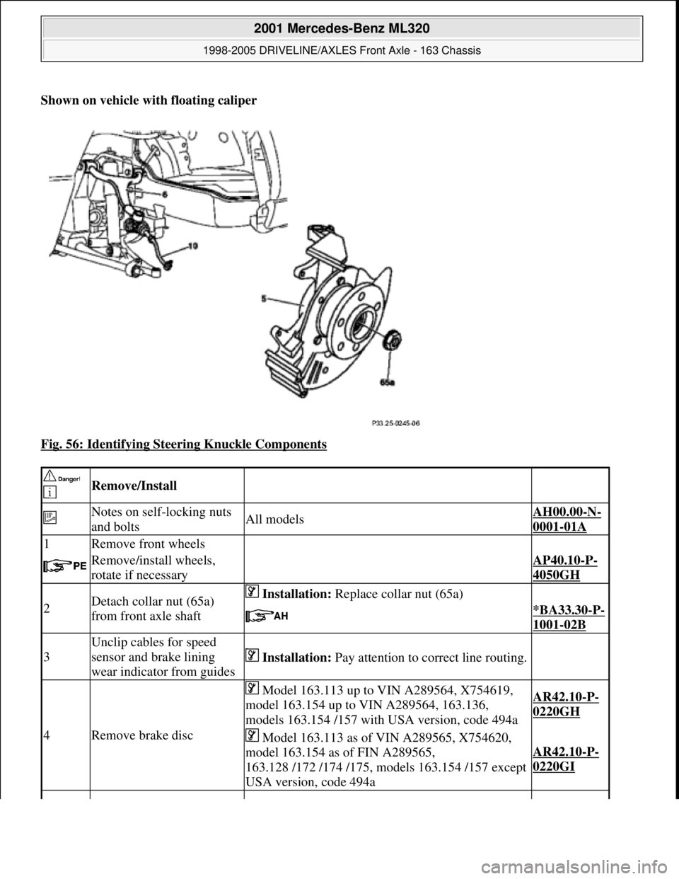
Shown on vehicle with floating caliper
Fig. 56: Identifying Steering Knuckle Components
Remove/Install
Notes on self-locking nuts
and boltsAll modelsAH00.00-N-
0001-01A
1Remove front wheels
Remove/install wheels,
rotate if necessaryAP40.10-P-
4050GH
2Detach collar nut (65a)
from front axle shaft Installation: Replace collar nut (65a)
*BA33.30-P-
1001-02B
3
Unclip cables for speed
sensor and brake lining
wear indicator from guides
Installation: Pay attention to correct line routing.
4Remove brake disc
Model 163.113 up to VIN A289564, X754619,
model 163.154 up to VIN A289564, 163.136,
models 163.154 /157 with USA version, code 494aAR42.10-P-
0220GH
Model 163.113 as of VIN A289565, X754620,
model 163.154 as of FIN A289565,
163.128 /172 /174 /175, models 163.154 /157 except
USA version, code 494a
AR42.10-P-
0220GI
2001 Mercedes-Benz ML320
1998-2005 DRIVELINE/AXLES Front Axle - 163 Chassis
me
Saturday, October 02, 2010 3:38:22 PMPage 36 © 2006 Mitchell Repair Information Company, LLC.
Page 2556 of 4133
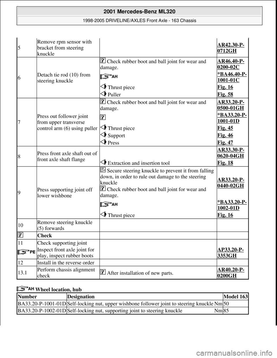
Wheel location, hub
5
Remove rpm sensor with
bracket from steering
knuckle
AR42.30-P-
0712GH
6Detach tie rod (10) from
steering knuckle
Check rubber boot and ball joint for wear and
damage.AR46.40-P-
0200-02C
*BA46.40-P-
1001-01C
Thrust pieceFig. 16
PullerFig. 58
7
Press out follower joint
from upper transverse
control arm (6) using puller
Check rubber boot and ball joint for wear and
damage.AR33.20-P-
0500-01GH
*BA33.20-P-
1001-01D
Thrust pieceFig. 45
SupportFig. 46
PressFig. 47
8Press front axle shaft out of
front axle shaft flange AR33.30-P-
0620-04GH
Extraction and insertion toolFig. 18
9Press supporting joint off
lower wishbone
Secure steering knuckle to prevent it from falling
down, in order to rule out damage to the steering
knuckle
Check rubber boot and ball joint for wear and
damage.
AR33.20-P-
0440-02GH
*BA33.20-P-
1002-01D
Thrust pieceFig. 16
10Remove steering knuckle
(5) forwards
Check
11Check supporting joint
Inspect front axle joint for
play, inspect rubber bootsAP33.20-P-
3353GH
12Install in the reverse order
13.1Perform chassis alignment
check After installation of new parts.AR40.20-P-
0200GH
NumberDesignationModel 163
BA33.20-P-1001-01DSelf-locking nut, upper wishbone follower joint to steering knuckleNm50
BA33.20-P-1002-01DSelf-locking nut, supporting joint to steering knuckleNm85
2001 Mercedes-Benz ML320
1998-2005 DRIVELINE/AXLES Front Axle - 163 Chassis
me
Saturday, October 02, 2010 3:38:22 PMPage 37 © 2006 Mitchell Repair Information Company, LLC.
Page 2595 of 4133

AF54.30-P-2064A
Fuel gauge not registering correctly after refueling vehicle
4.2.03
MODEL
163.### #A as of 221506 up to 364039,
163.### #X as of 734088 up to 777100
Operation no. of operation texts or standard texts and flat rates
Sector
Op. no.
Operation text
Time
Acc. no.
Code
P
023803
RECODE INSTRUMENT CLUSTER
003 WU/0.3 h
54 208 50
---
Damage Code
Cause
Remedy
Refuel recognition software may not
recognize incremental refueling (< 7 L).
In case of complaint
#
The fuel gauge operation defaults to back-
up mode, and continuously decreases last
stored sensor value based on consumption
data supplied via engine management. This
continues until either refuel recognition or
instrument cluster (A1) reset occurs (via
STAR Diagnosis or power disconnect).
Vehicles with 83 L fuel tank (as of MY2002)
are more susceptible to this condition.
This applies only to instrument clusters
(A1) with diagnostic version 3/05, 3/06,
and 3/07.
1
Connect STAR Diagnosis.
2
Under "Control module adaptations" in
"ICM" menu, set "Fuel tank characteristic
curve" from "Normal" to "Direct sensor
value".
DO NOT replace the instrument cluster
(A1) or fuel pump assembly (M3) for this
condition.
Copyright DaimlerChrysler AG 28.05.2006 CD-Ausgabe G/10/04 . This WIS print-out will not be recorde
d by Modification services.
Page 1
Page 2596 of 4133
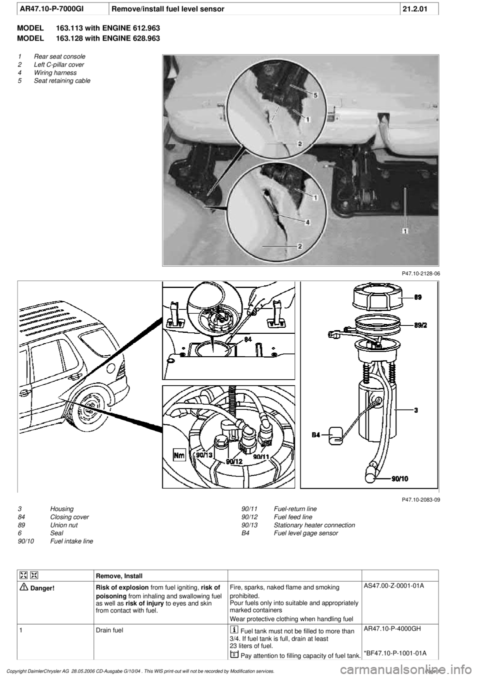
AR47.10-P-7000GI
Remove/install fuel level sensor
21.2.01
MODEL
163.113 with ENGINE 612.963
MODEL
163.128 with ENGINE 628.963
P47.10-2128-06
1
Rear seat console
2
Left C-pillar cover
4
Wiring harness
5
Seat retaining cable
P47.10-2083-09
3
Housing
84
Closing cover
89
Union nut
6
Seal
90/10
Fuel intake line
90/11
Fuel-return line
90/12
Fuel feed line
90/13
Stationary heater connection
B4
Fuel level gage sensor
Remove, Install
Danger!
Risk of explosion
from fuel igniting,
risk of
poisoning
from inhaling and swallowing fuel
as well as
risk of injury
to eyes and skin
from contact with fuel.
Fire, sparks, naked flame and smoking
prohibited.
Pour fuels only into suitable and appropriately
marked containers
Wear protective clothing when handling fuel
AS47.00-Z-0001-01A
1
Drain fuel
Fuel tank must not be filled to more than
3/4. If fuel tank is full, drain at least
23 liters of fuel.
AR47.10-P-4000GH
Pay attention to filling capacity of fuel tank.
*BF47.10-P-1001-01A
Copyright DaimlerChrysler AG 28.05.2006 CD-Ausgabe G/10/04 . This WIS print-out will not be recorde
d by Modification services.
Page 1
Page 2597 of 4133

2
Remove covers at seat frame of 60% bench
seat
As of VIN A145273, X708319.
AR91.12-P-1100GH
Only remove the covers which are
identified in the document with A, D and E.
3
Fold 60% bench seat forward into footwell
As of VIN A145273, X708319. See
operator's manual.
4
Pull floor covering below rear seat mounting
bracket (1) of 60% seat forward
Ensure that the floor covering is not torn
when pulled forward.
As of VIN A145273, X708319.
5
Pull floor covering below front corner of trim
panel of C-pillar (2) forward
Ensure that the floor covering is not torn
when pulled forward.
As of VIN A145273, X708319.
6
Cut into floor covering directly behind seat
retaining cable (5)
Ensure that the wiring harness (4) is not
damaged when cutting into floor covering.
As of VIN A145273, X708319. broken line
marks cut-in.
7
Turn back floor covering to gain access to
cap (84)
Do not kink floor covering.
8
Remove cap (84)
Cap (84) is sealed in with body sealer.
Heat with hot air blower to make it easier to
remove.
Installation:
Replace cap and install with
new sealing compound.
9
Detach fuel feed line (90/12) and fuel return
line (90/11) and, if fitted, the fuel line at
connection (90/13)
Do not kink the fuel lines.
If no stationary heater is fitted to vehicle,
do not remove connection (90/13) otherwise
housing will be damaged.
*163589003700
10
Remove nut (89)
*163589010700
*BA47.20-P-1006-01B
11
Remove housing (3)
Fuel lever sensor and housing are a
single part and cannot be removed separately.
Installation:
Re-install nut (89) together
with seal (89/2).
Apply a thin film of oil to seal.
12
Install in the reverse order
Fuel pump
Number
Designation
Engine 612Engine 628
BA47.20-P-1006-01B
Union nut for fuel tank sensor on fuel
tank
Nm
6565
Fuel tank
Number
Designation
Models
163.113/
136/154/
172 up to
31.08.01
Model
163.113/
136/154/
172 as of
01.09.01
Model
163.157/
175
Model
163.128
BF47.10-P-1001-01A
Fuel tank capacity
Total capacity
Liter
728383
Reserve capacity
Liter
101212
Copyright DaimlerChrysler AG 28.05.2006 CD-Ausgabe G/10/04 . This WIS print-out will not be recorde
d by Modification services.
Page 2