1997 MERCEDES-BENZ ML350 sensor
[x] Cancel search: sensorPage 2410 of 4133
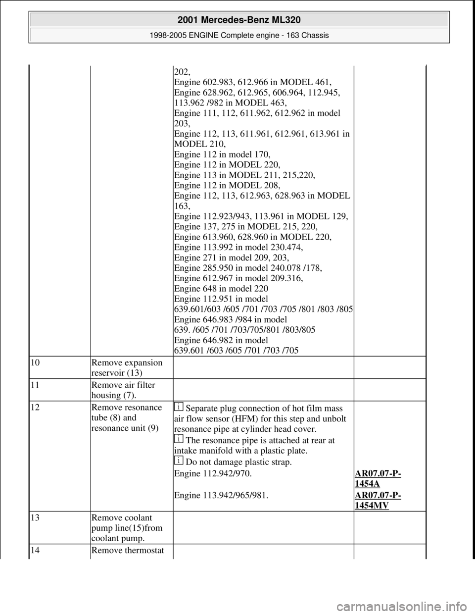
202,
Engine 602.983, 612.966 in MODEL 461,
Engine 628.962, 612.965, 606.964, 112.945,
113.962 /982 in MODEL 463,
Engine 111, 112, 611.962, 612.962 in model
203,
Engine 112, 113, 611.961, 612.961, 613.961 in
MODEL 210,
Engine 112 in model 170,
Engine 112 in MODEL 220,
Engine 113 in MODEL 211, 215,220,
Engine 112 in MODEL 208,
Engine 112, 113, 612.963, 628.963 in MODEL
163,
Engine 112.923/943, 113.961 in MODEL 129,
Engine 137, 275 in MODEL 215, 220,
Engine 613.960, 628.960 in MODEL 220,
Engine 113.992 in model 230.474,
Engine 271 in model 209, 203,
Engine 285.950 in model 240.078 /178,
Engine 612.967 in model 209.316,
Engine 648 in model 220
Engine 112.951 in model
639.601/603 /605 /701 /703 /705 /801 /803 /805
Engine 646.983 /984 in model
639. /605 /701 /703/705/801 /803/805
Engine 646.982 in model
639.601 /603 /605 /701 /703 /705
10Remove expansion
reservoir (13)
11Remove air filter
housing (7).
12Remove resonance
tube (8) and
resonance unit (9) Separate plug connection of hot film mass
air flow sensor (HFM) for this step and unbolt
resonance pipe at cy linder head cover.
The resonance pipe is attached at rear at
intake manifold with a plastic plate.
Do not damage plastic strap.
Engine 112.942/970.AR07.07-P-
1454A
Engine 113.942/965/981.AR07.07-P-
1454MV
13Remove coolant
pump line(15)from
coolant pump.
14Remove thermostat
2001 Mercedes-Benz ML320
1998-2005 ENGINE Complete engine - 163 Chassis
me
Saturday, October 02, 2010 3:17:56 PMPage 54 © 2006 Mitchell Repair Information Company, LLC.
Page 2412 of 4133
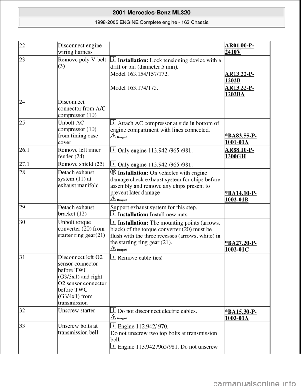
22Disconnect engine
wiring harness AR01.00-P-
2410V
23Remove poly V-belt
(3) Installation: Lock tensioning device with a
drift or pin (diameter 5 mm).
Model 163.154/157/172.AR13.22-P-
1202B
Model 163.174/175.AR13.22-P-
1202BA
24Disconnect
connector from A/C
compressor (10)
25Unbolt AC
compressor (10)
from timing case
cover Attach AC compressor at side in bottom of
engine compartment with lines connected.
*BA83.55-P-
1001-01A
26.1Remove left inner
fender (24) Only engine 113.942 /965 /981.AR88.10-P-
1300GH
27.1Remove shield (25) Only engine 113.942 /965 /981.
28Detach exhaust
system (11) at
exhaust manifold Installation: On vehicles with engine
damage check exhaust sy stem for chips before
assembly and remove any chips present to
prevent later damage
*BA14.10-P-
1002-01B
29Detach exhaust
bracket (12)Support exhaust system for this step.
Installation: Install new nuts.
30Unbolt torque
converter (20) from
starter ring gear(21) Installation: The mounting points (arrows,
black) of the torque converter (20) must be
flush with the three recesses (arrows, white) in
the starting ring gear (21).
*BA27.20-P-
1002-01C
31Disconnect left O2
sensor connector
before TWC
(G3/3x1) and right
O2 sensor connector
before TWC
(G3/4x1) from
transmission Remove cable ties!
32Unscrew starter Do not disconnect electric cables.
*BA15.30-P-
1003-01A
33Unscrew bolts at
transmission bell Engine 112.942/ 970.
Do not unscrew two top bolts at transmission
bell.
Engine 113.942 /965/ 981. Do not unscrew
2001 Mercedes-Benz ML320
1998-2005 ENGINE Complete engine - 163 Chassis
me
Saturday, October 02, 2010 3:17:56 PMPage 56 © 2006 Mitchell Repair Information Company, LLC.
Page 2419 of 4133
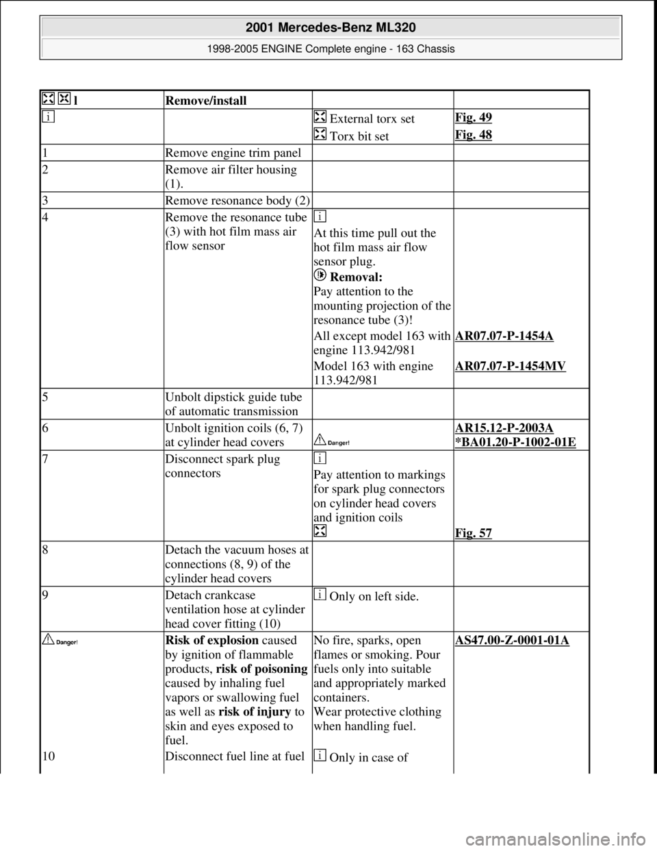
lRemove/install
External torx setFig. 49
Torx bit setFig. 48
1Remove engine trim panel
2Remove air filter housing
(1).
3Remove resonance body (2)
4Remove the resonance tube
(3) with hot film mass air
flow sensor
At this time pull out the
hot film mass air flow
sensor plug.
Removal:
Pay attention to the
mounting projection of the
resonance tube (3)!
All except model 163 with
engine 113.942/981AR07.07-P-1454A
Model 163 with engine
113.942/981AR07.07-P-1454MV
5Unbolt dipstick guide tube
of automatic transmission
6Unbolt ignition coils (6, 7)
at cylinder head covers
AR15.12-P-2003A
*BA01.20
-P-1002-01E
7Disconnect spark plug
connectors
Pay attention to markings
for spark plug connectors
on cylinder head covers
and ignition coils
Fig. 57
8Detach the vacuum hoses at
connections (8, 9) of the
cylinder head covers
9Detach crankcase
ventilation hose at cylinder
head cover fitting (10) Only on left side.
Risk of explosion caused
by ignition of flammable
products, risk of poisoning
caused by inhaling fuel
vapors or swallowing fuel
as well as risk of injury to
skin and eyes exposed to
fuel.No fire, sparks, open
flames or smoking. Pour
fuels only into suitable
and appropriately marked
containers.
Wear protective clothing
when handling fuel.AS47.00-Z-0001-01A
10Disconnect fuel line at fuel Only in case of
2001 Mercedes-Benz ML320
1998-2005 ENGINE Complete engine - 163 Chassis
me
Saturday, October 02, 2010 3:17:56 PMPage 63 © 2006 Mitchell Repair Information Company, LLC.
Page 2442 of 4133
Engine 112 in model 208,
Engine 112, 113, 612.963, 628.963 in model
163,
Engines 112.923/943, 113.961 in model 129,
Engines 137, 275 in models 215, 220,
Engines 613.960, 628.960 in model 220,
Engine 113.992 in model 230.474,
Engine 271 in MODELS 209, 203,
Engine 285.950 in models 240.078 /178,
Engine 612.967 in model 209.316,
Engine 648 in model 220 Engine 112.951 in
model
639.601/603 /605 /701 /703 /705 /801 /803 /805
Engine 646.983 /984 in model
639. /605 /701 /703/705/801 /803/805
Engine 646.982 in model
639.601 /603 /605 /701 /703 /705
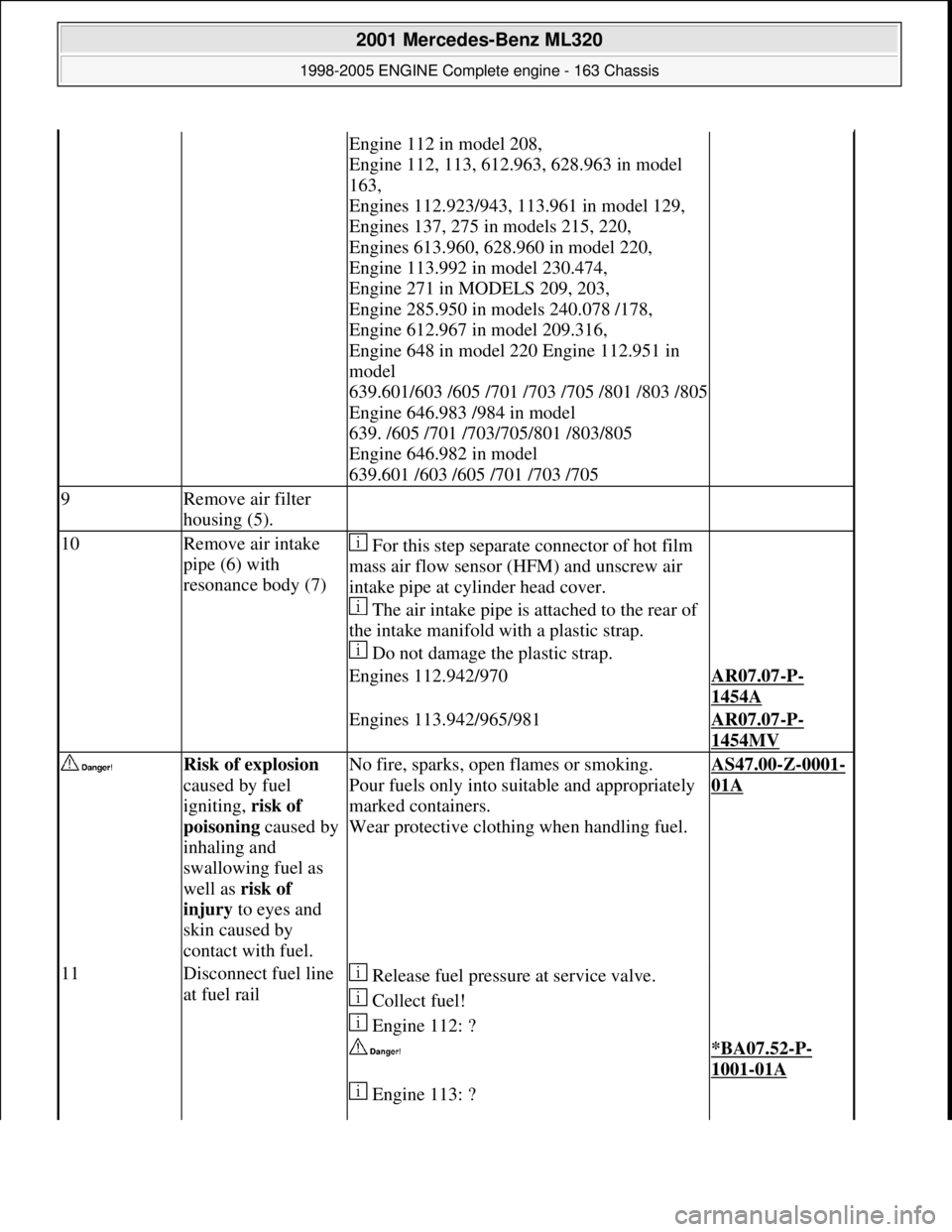
9Remove air filter
housing (5).
10Remove air intake
pipe (6) with
resonance body (7) For this step separate connector of hot film
mass air flow sensor (HFM) and unscrew air
intake pipe at cylinder head cover.
The air intake pipe is attached to the rear of
the intake manifold with a plastic strap.
Do not damage the plastic strap.
Engines 112.942/970AR07.07-P-
1454A
Engines 113.942/965/981AR07.07-P-
1454MV
Risk of explosion
caused by fuel
igniting, risk of
poisoning caused by
inhaling and
swallowing fuel as
well as risk of
injury to eyes and
skin caused by
contact with fuel.No fire, sparks, open flames or smoking.
Pour fuels only into suitable and appropriately
marked containers.
Wear protective clothing when handling fuel.AS47.00-Z-0001-
01A
11Disconnect fuel line
at fuel rail Release fuel pressure at service valve.
Collect fuel!
Engine 112: ?
*BA07.52-P-
1001-01A
Engine 113: ?
2001 Mercedes-Benz ML320
1998-2005 ENGINE Complete engine - 163 Chassis
me
Saturday, October 02, 2010 3:17:57 PMPage 86 © 2006 Mitchell Repair Information Company, LLC.
Page 2443 of 4133
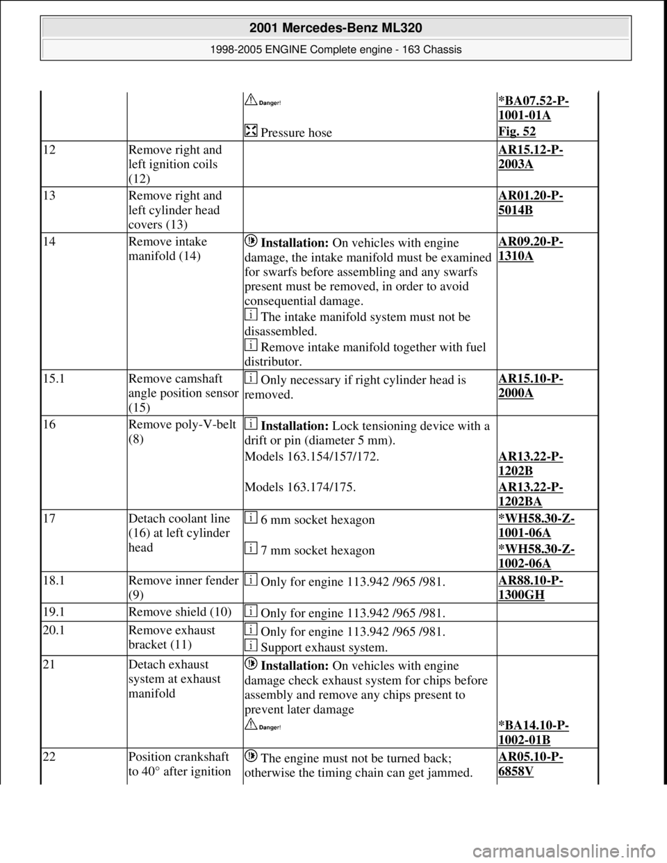
*BA07.52-P-
1001-01A
Pressure hoseFig. 52
12Remove right and
left ignition coils
(12) AR15.12-P-
2003A
13Remove right and
left cylinder head
covers (13) AR01.20-P-
5014B
14Remove intake
manifold (14) Installation: On vehicles with engine
damage, the intake manifold must be examined
for swarfs before assembling and any swarfs
present must be removed, in order to avoid
consequential damage.
The intake manifold system must not be
disassembled.
Remove intake manifold together with fuel
distributor.AR09.20-P-
1310A
15.1Remove camshaft
angle position sensor
(15) Only necessary if right cylinder head is
removed.AR15.10-P-
2000A
16Remove poly-V-belt
(8) Installation: Lock tensioning device with a
drift or pin (diameter 5 mm).
Models 163.154/157/172.AR13.22-P-
1202B
Models 163.174/175.AR13.22-P-
1202BA
17Detach coolant line
(16) at left cylinder
head 6 mm socket hexagon*WH58.30-Z-
1001-06A
7 mm socket hexagon*WH58.30-Z-
1002-06A
18.1Remove inner fender
(9) Only for engine 113.942 /965 /981.AR88.10-P-
1300GH
19.1Remove shield (10) Only for engine 113.942 /965 /981.
20.1Remove exhaust
bracket (11) Only for engine 113.942 /965 /981.
Support exhaust system.
21Detach exhaust
system at exhaust
manifold Installation: On vehicles with engine
damage check exhaust sy stem for chips before
assembly and remove any chips present to
prevent later damage
*BA14.10-P-
1002-01B
22Position crankshaft
to 40° after ignition The engine must not be turned back;
otherwise the timing chain can get jammed. AR05.10-P-
6858V
2001 Mercedes-Benz ML320
1998-2005 ENGINE Complete engine - 163 Chassis
me
Saturday, October 02, 2010 3:17:57 PMPage 87 © 2006 Mitchell Repair Information Company, LLC.
Page 2460 of 4133
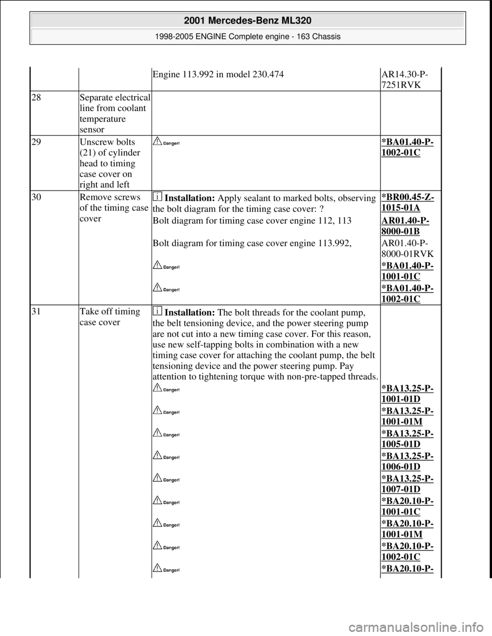
Engine 113.992 in model 230.474AR14.30-P-
7251RVK
28Separate electrical
line from coolant
temperature
sensor
29Unscrew bolts
(21) of cylinder
head to timing
case cover on
right and left *BA01.40-P-
1002-01C
30Remove screws
of the timing case
cover Installation: Apply sealant to marked bolts, observing
the bolt diagram for th e timing case cover: ?*BR00.45-Z-
1015-01A
Bolt diagram for timing case cover engine 112, 113AR01.40-P-
8000-01B
Bolt diagram for timing case cover engine 113.992,AR01.40-P-
8000-01RVK
*BA01.40-P-
1001-01C
*BA01.40-P-
1002-01C
31Take off timing
case cover Installation: The bolt threads for the coolant pump,
the belt tensioning device, and the power steering pump
are not cut into a new timing case cover. For this reason,
use new self-tapping bolts in combination with a new
timing case cover for attaching the coolant pump, the belt
tensioning device and th e power steering pump. Pay
attention to tightening torque with non-pre-tapped threads.
*BA13.25-P-
1001-01D
*BA13.25-P-
1001-01M
*BA13.25-P-
1005-01D
*BA13.25-P-
1006-01D
*BA13.25-P-
1007-01D
*BA20.10-P-
1001-01C
*BA20.10-P-
1001-01M
*BA20.10-P-
1002-01C
*BA20.10-P-
2001 Mercedes-Benz ML320
1998-2005 ENGINE Complete engine - 163 Chassis
me
Saturday, October 02, 2010 3:17:57 PMPage 104 © 2006 Mitchell Repair Information Company, LLC.
Page 2487 of 4133
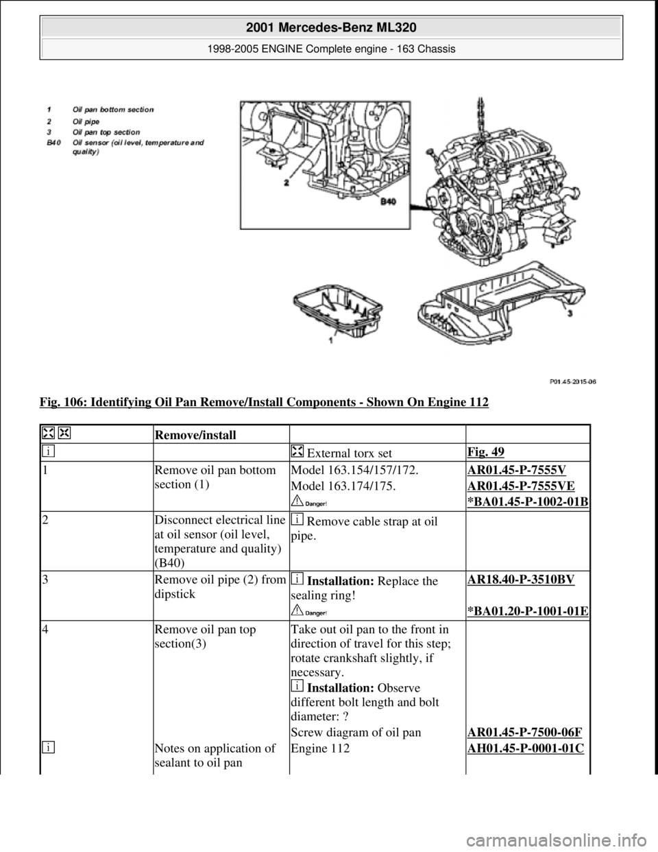
Fig. 106: Identifying Oil Pan Remove/Install Components - Shown On Engine 112
Remove/install
External torx setFig. 49
1Remove oil pan bottom
section (1)Model 163.154/157/172.AR01.45-P-7555V
Model 163.174/175.AR01.45-P-7555VE
*BA01.45-P-1002-01B
2Disconnect electrical line
at oil sensor (oil level,
temperature and quality)
(B40) Remove cable strap at oil
pipe.
3Remove oil pipe (2) from
dipstick Installation: Replace the
sealing ring!AR18.40-P-3510BV
*BA01.20-P-1001-01E
4Remove oil pan top
section(3)Take out oil pan to the front in
direction of travel for this step;
rotate crankshaft slightly, if
necessary.
Installation: Observe
different bolt length and bolt
diameter: ?
Screw diagram of oil panAR01.45-P-7500-06F
Notes on application of
sealant to oil panEngine 112AH01.45-P-0001-01C
2001 Mercedes-Benz ML320
1998-2005 ENGINE Complete engine - 163 Chassis
me
Saturday, October 02, 2010 3:17:58 PMPage 131 © 2006 Mitchell Repair Information Company, LLC.
Page 2491 of 4133
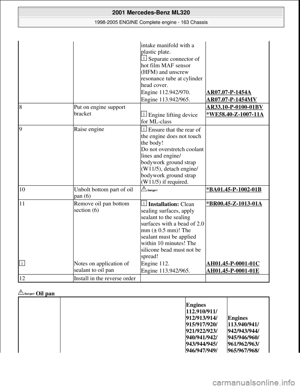
Oil pan
intake manifold with a
plastic plate.
Separate connector of
hot film MAF sensor
(HFM) and unscrew
resonance tube at cylinder
head cover.
Engine 112.942/970.AR07.07-P-1454A
Engine 113.942/965.AR07.07-P-1454MV
8Put on engine support
bracket AR33.10-P-0100-01BV
Engine lifting device
for ML-class*WE58.40-Z-1007-11A
9Raise engine Ensure that the rear of
the engine does not touch
the body!
Do not overstretch coolant
lines and engine/
bodywork ground strap
(W11/5), detach engine/
bodywork ground strap
(W11/5) if required.
10Unbolt bottom part of oil
pan (6) *BA01.45-P-1002-01B
11Remove oil pan bottom
section (6) Installation: Clean
sealing surfaces, apply
sealant to the sealing
surfaces with a bead of 2.0
mm (± 0.5 mm)! The
sealant must be applied
within 10 minutes! The
silicone bead must not be
spread!*BR00.45-Z-1013-01A
Notes on application of
sealant to oil panEngine 112.AH01.45-P-0001-01C
Engine 113.942/965.AH01.45-P-0001-01E
12Install in the reverse order
Engines
112.910/911/
912/913/914/
915/917/920/
921/922/923/
940/941/942/
943/944/945/
946/947/949/
Engines
113.940/941/
942/943/944/
945/946/960/
961/962/963/
965/967/968/
2001 Mercedes-Benz ML320
1998-2005 ENGINE Complete engine - 163 Chassis
me
Saturday, October 02, 2010 3:17:58 PMPage 135 © 2006 Mitchell Repair Information Company, LLC.