Page 1516 of 4133
XENON HEADLAMPS, FUNCTION - GF82.10-P-2007-01GHA
The lighting technology, known as bi-xenon 70 , is located in the outer headlamps.
When the low beam lamps are switched on the xenon headlamp control module (E1 n1, E2n1) activates the
xenon headlamp control module and ignition module (E1n2, E2n2) via the control voltage within a few
milliseconds.
A high-voltage surge from the ignition device ignites the xenon lamps, and in doing so an electric arc is formed
between the electrodes. When an arc of sufficient stability is detected, the control electronics of the control
module (E1 n1, E2n1) switches over to power-limiting mode.
The light generated previously in a gas discharge lamp (D2S lamp) is not reflected in bi-xenon 70 headlamps,
but instead it is sent directly through a lens optical system with a lens diameter of 70 mm.
Using the mask (B), which is positioned between the gas discharge lamp and the lens optical system, the beam
of light is partially masked for the low beam so that oncoming traffic is not blinded.
For the high beam, the mask (B) is electro-mechanically folded to the side using the solenoid (M).
If the solenoid (M) should fail or a supply line breaks, the mask (B) remains mechanically held in the low
beam position, always between the gas discharge lamp and the lens optical system.
In order to make the extremely bright light more acceptable to other road users, the lens aperture area with its
dotted characteristic is optically enlarged.
This is possible on account of the specially formed areas which surround the lens. In addition, the light can pass
through a number of chrome-plated strips from the rear. A portion of the diffused light is intercepted by the
lower section of the surface area and reflected to the upper section of the chrome-plated longitudinal strips.
For technical reasons the xenon lamp has a timed startup characteristic. After switch on, 50 % of the luminosity
is reached within 1 to 2 seconds and full luminosity is achieved after another approx. 30 seconds.
XENON HEADLAMP, LOCATION/DESIGN/FUNCTION - GF82.10-P-2007GH
MODELS 163.113 /136 /154 /172 up to 31.08.01 with CODE (612b) xenon headlamp unit with CODE
(U47) conversion package
MODELS 163.174 up to 31.08.01, 163.113 /128 /136 /154 /172 as of 01.09.01
Design:
From model
year 2002 (as of 1.9.01) the xenon headlamps are installed as standard.
2001 Mercedes-Benz ML320
1998-2005 ACCESSORIES & BODY, CAB Electrical System - Body - 163 Chassis
me
Saturday, October 02, 2010 3:30:04 PMPage 21 © 2006 Mitchell Repair Information Company, LLC.
Page 1517 of 4133
Fig. 10: Identifying Xenon Headlamp Components
XENON HEADLAMP, LOCATION/DESIGN/FUNCTION - GF82.10-P-2007GHA
MODELS 163.113 /128 /154 as of 1.9.01, 163.157, 163.172 /174 as of 1.9.01 with CODE (614) Bi-xenon
headlamp unit
Design:
Xenon headlamps,
functionModels 163.113,
163.136, 163.154,
163.172, 163.174 up to
31.08.01GF82.10-P-2007-01GH
2001 Mercedes-Benz ML320
1998-2005 ACCESSORIES & BODY, CAB Electrical System - Body - 163 Chassis
me
Saturday, October 02, 2010 3:30:04 PMPage 22 © 2006 Mitchell Repair Information Company, LLC.
Page 1518 of 4133
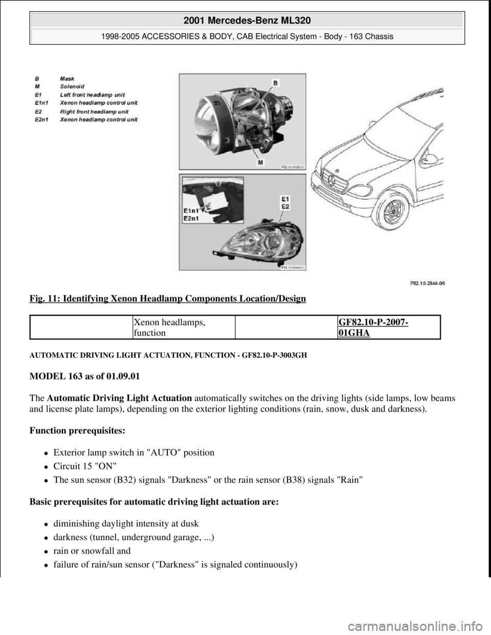
Fig. 11: Identifying Xenon Headlamp Components Location/Design
AUTOMATIC DRIVING LIGHT ACTUATION, FUNCTION - GF82.10-P-3003GH
MODEL 163 as of 01.09.01
The Automatic Driving Light Actuation automatically switches on the driving lights (side lamps, low beams
and license plate lamps), depending on the exterior lighting conditions (rain, snow, dusk and darkness).
Function prerequisites:
Exterior lamp switch in "AUTO" position
Circuit 15 "ON"
The sun sensor (B32) signals "Darkness" or the rain sensor (B38) signals "Rain"
Basic prerequisites for automatic driving light actuation are:
diminishing daylight intensity at dusk
darkness (tunnel, underground garage, ...)
rain or snowfall and
failure of rain/sun sensor ("Darkness" is signaled continuously)
Xenon headlamps,
function GF82.10-P-2007-
01GHA
2001 Mercedes-Benz ML320
1998-2005 ACCESSORIES & BODY, CAB Electrical System - Body - 163 Chassis
me
Saturday, October 02, 2010 3:30:04 PMPage 23 © 2006 Mitchell Repair Information Company, LLC.
Page 1520 of 4133
during the day only the low beam is on
when dark, the side lamps, license plate lamps as well as the switch and controls illumination (circuit
58d) are switched on
With halogen headlights the low beam is operated during the day with a reduced voltage
The lighting switches off automatically if the gearshift lever remains in "P" or "N" position for more than
3 min
Scandinavia
with daytime running lamps the low beam, the side lamps and the license plate lamps are active
the daytime running lamps switch off if the light switch assumes the "side lamps ON" position
Other countries
with daytime running lamps the low beam, the side lamps and the license plate lamps are active
the daytime running lamps are always active
The high beams can only be switched on if the exterior lamp switch:
is at "low beam"
is at "AUTO" and "Darkness" is detected
daytime running lamps for "Other countries" has been coded
CONTENTS - FUNCTION DESCRIPTION OF EXTERIOR LIGHTING, LOCATION/ PURPOSE/DESIGN/FUNCTION -
GF82.10-P-9999B
MODELS 129, 140, 202, 208, 210, 163 up to 31.08.01 with CODE (612b) xenon headlamp unit
MODEL 163 as of 01.09.01 with CODE (614) bi-xenon headlamp unit
Automatic driving light
actuation, function GF82.10-P-3003GH
Table of contents,
function description for
exterior lighting GF82.10-P-0999A
Axle sensor for headlamp range
adjustment, location/taskMODELS 129, 140,
202, 208, 210 with
code 612b xenon
headlamp unitGF82.10-P-2100A
Headlamp range adjustment motor,
location/ taskMODELS 129, 140,
202, 208, 210 with
code 612b xenon
headlamp unitGF82.10-P-2101A
2001 Mercedes-Benz ML320
1998-2005 ACCESSORIES & BODY, CAB Electrical System - Body - 163 Chassis
me
Saturday, October 02, 2010 3:30:04 PMPage 25 © 2006 Mitchell Repair Information Company, LLC.
Page 1521 of 4133
HEADLAMP CLEANING SYSTEM (HCS), LOCATION OF COMPONENTS - GF82.15-P-0002-03GH
Control module for headlamp range
adjustment, location/taskMODELS 129, 140,
202, 208, 210 with
code 612b xenon
headlamp unitGF82.10-P-2102A
Xenon headlamp, position/functionMODELS 129, 140,
202, 208, 210 with
code 612b xenon
headlamp unitGF82.10-P-2001A
Xenon headlamp, position/functionModel 215GF82.10-P-2001B
Xenon headlamp,
position/design/functionMODEL 163 up to
31.08.01GF82.10-P-2007GH
MODEL 163 as of
01.09.01GF82.10-P-
2007GHA
Xenon headlamp control module,
location/taskMODELS 129, 140,
202, 208, 210 with
code 612b xenon
headlamp unitGF82.10-P-2104A
Xenon headlamp ignition module,
location/taskMODELS 129, 140,
202, 208, 210 with
code 612b xenon
headlamp unitGF82.10-P-2105A
Table of contents, function
description for exterior lighting GF82.10-P-0999A
2001 Mercedes-Benz ML320
1998-2005 ACCESSORIES & BODY, CAB Electrical System - Body - 163 Chassis
me
Saturday, October 02, 2010 3:30:04 PMPage 26 © 2006 Mitchell Repair Information Company, LLC.
Page 1522 of 4133
Fig. 12: Identifying Headlamp Cleaning System (HCS) Components Location
HEADLAMP CLEANING SYSTEM (HCS), FUNCTION - GF82.15-P-0002GH
MODEL 163 as of 01.09.01 with CODE ( 600a) headlamp cleaning system
Connection diagram
Fig. 13: Identifying Headlamp Cleaning Sy stem (HCS) Components Connection Diagram
2001 Mercedes-Benz ML320
1998-2005 ACCESSORIES & BODY, CAB Electr ical System - Body - 163 Chassis
me
Saturday, October 02, 2010 3:30:04 PMPage 27 © 2006 Mitchell Repair Information Company, LLC.
Page 1523 of 4133
![MERCEDES-BENZ ML350 1997 Complete Repair Manual Function prerequisites:
Circuit 15 ON
Function
The headlamp cleaning system is switched on by pressing the SRA [HCS] switch (S4/1) .
The corresponding input of the Extended Activity M MERCEDES-BENZ ML350 1997 Complete Repair Manual Function prerequisites:
Circuit 15 ON
Function
The headlamp cleaning system is switched on by pressing the SRA [HCS] switch (S4/1) .
The corresponding input of the Extended Activity M](/manual-img/4/57306/w960_57306-1522.png)
Function prerequisites:
Circuit 15 ON
Function
The headlamp cleaning system is switched on by pressing the SRA [HCS] switch (S4/1) .
The corresponding input of the Extended Activity Module (EAM) (N10/1) , which receives the input
from the switch, sends the signal to relay 5 (F2k5) .
The relay switches circuit 30 , for a duty cycle of approx. 1 second, through to the HCS pump (M5/2) .
The HCS pump (M5/2) builds up pressure in the washing water line.
The water pressure acts against the return springs of the telescopic nozzles.
The telescopic nozzles extend and spray washing water onto the headlamp glass.
After the duty cycle, the pressure in the washing water line drops again and the telescopic nozzles move
back to their starting position due to spring load.
Pressing the SRA [HCS] switch (S4/1) again during an ongoing headlamp cleaning cycle has no effect.
A further cleaning cycle can only be initiated after the previous cycle has ended.
TABLE OF CONTENTS, FUNCTION DESCRIPTION FOR HEADLAMP CLEANING SYSTEM (HCS) - GF82.15-P-0998GHZ
MODEL 163 as of 01.09.01 with CODE (600a) headlamp cleaning system
FUNCTION OF HEADLAMP CLEANING SYSTEM TELESCOPIC NOZZLES - GF82.15-P-2100-04GH
After the HCS pump (M5/2) has started to operate, pressure builds up in the washing water line for approx. 1
Headlamp cleaning system (HCS),
location of components GF82.15-P-0002-
03GH
Telescopic nozzles for headlamp
cleaning system,
location/task/design/function GF82.15-P-2100GH
Extended Activity Module,
location/task/design GF54.21-P-4107GK
Headlamp cleaning system
(HCS), function GF82.15-P-0002GH
Headlamp cleaning system
(HCS), location of components GF82.15-P-0002-
03GH
Survey of system components
for headlamp cleaning system
(HCS), location/task/design/
function GF82.15-P-9998GHZ
2001 Mercedes-Benz ML320
1998-2005 ACCESSORIES & BODY, CAB Electrical System - Body - 163 Chassis
me
Saturday, October 02, 2010 3:30:04 PMPage 28 © 2006 Mitchell Repair Information Company, LLC.
Page 1524 of 4133
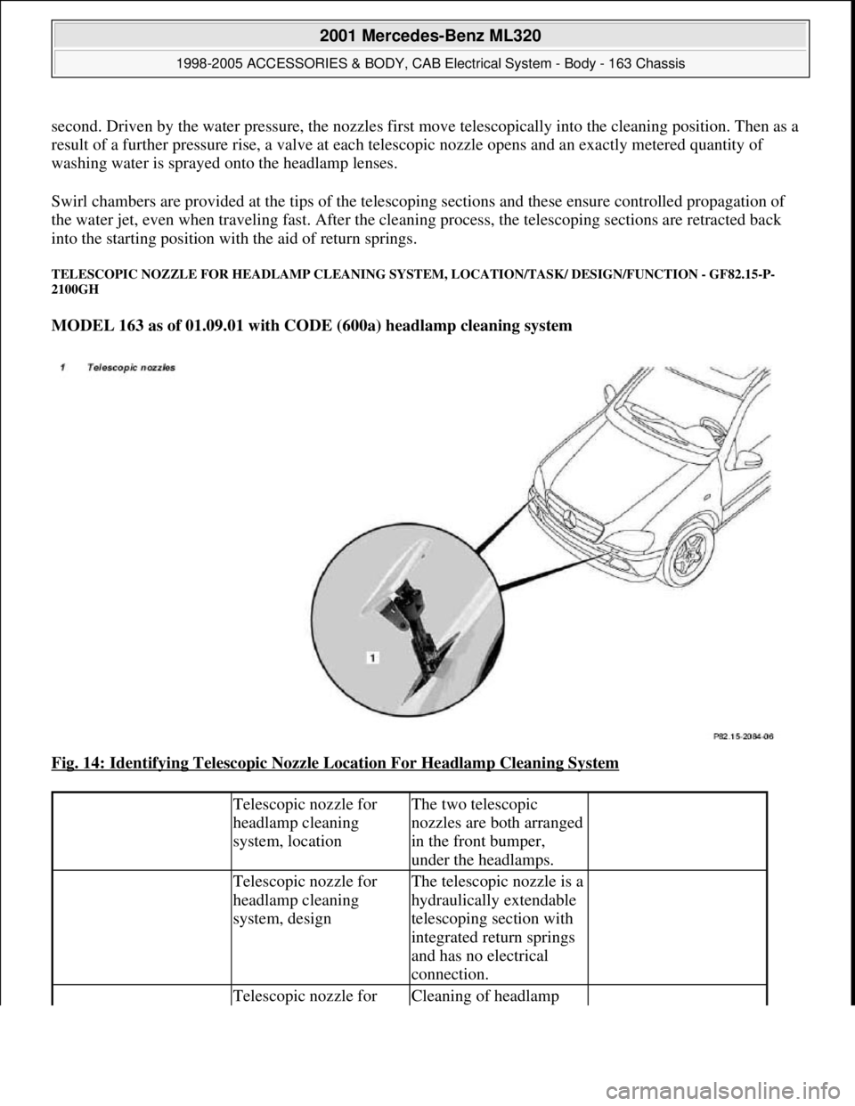
second. Driven by the water pressure, the nozzles first move telescopically into the cleaning position. Then as a
result of a further pressure rise, a valve at each telescopic nozzle opens and an exactly metered quantity of
washing water is sprayed onto the headlamp lenses.
Swirl chambers are provided at the tips of the telescoping sections and these ensure controlled propagation of
the water jet, even when traveling fast. After the cleaning process, the telescoping sections are retracted back
into the starting position with the aid of return springs.
TELESCOPIC NOZZLE FOR HEADLAMP CLEANING SYSTEM, LOCATION/TASK/ DESIGN/FUNCTION - GF82.15-P-
2100GH
MODEL 163 as of 01.09.01 with CODE (600a) headlamp cleaning system
Fig. 14: Identifying Telescopic Nozzle Location For Headlamp Cleaning System
Telescopic nozzle for
headlamp cleaning
system, locationThe two telescopic
nozzles are both arranged
in the front bumper,
under the headlamps.
Telescopic nozzle for
headlamp cleaning
system, designThe telescopic nozzle is a
hydraulically extendable
telescoping section with
integrated return springs
and has no electrical
connection.
Telescopic nozzle for Cleaning of headlamp
2001 Mercedes-Benz ML320
1998-2005 ACCESSORIES & BODY, CAB Electrical System - Body - 163 Chassis
me
Saturday, October 02, 2010 3:30:04 PMPage 29 © 2006 Mitchell Repair Information Company, LLC.