Page 1756 of 4133

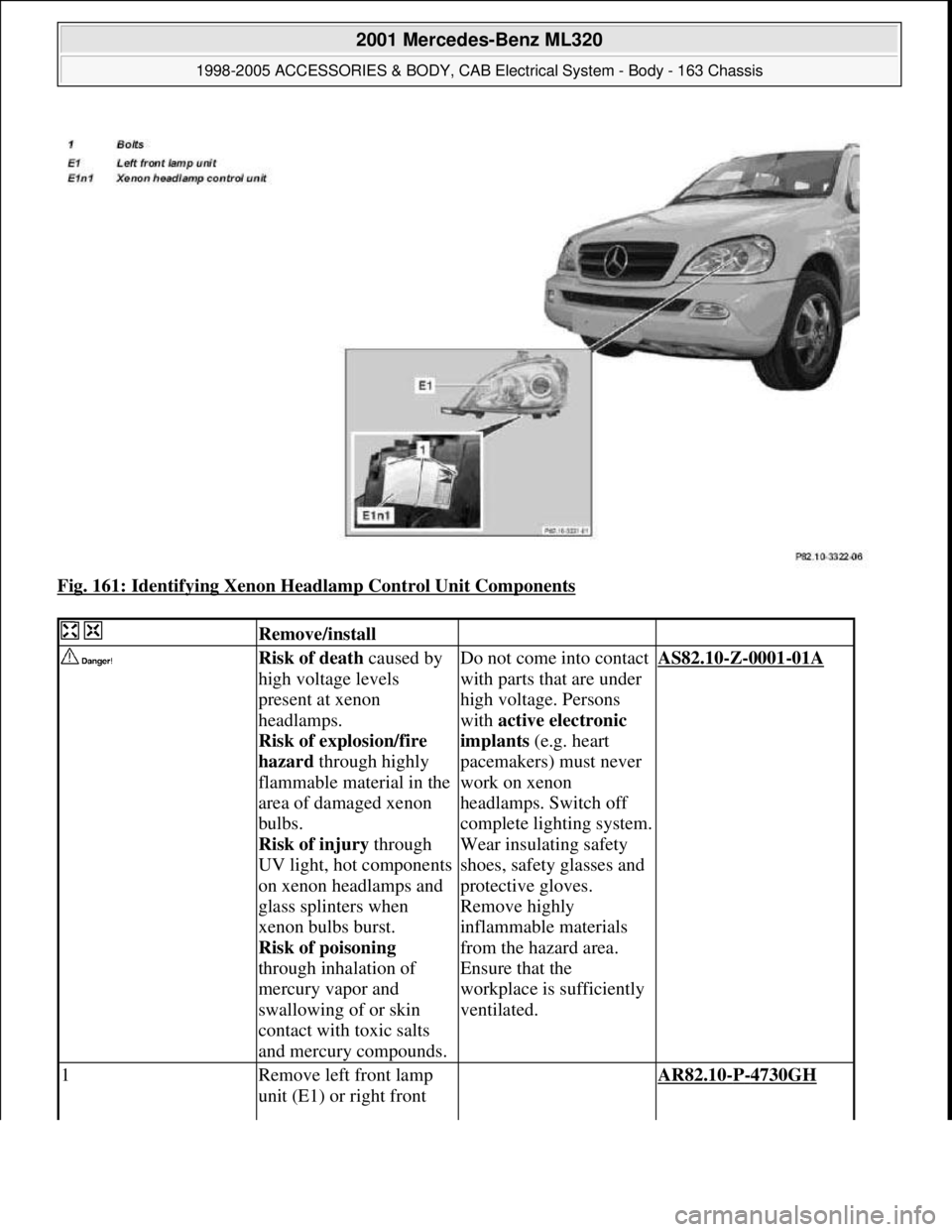
Fig. 161: Identifying Xenon Headlamp Control Unit Components
Remove/install
Risk of death caused by
high voltage levels
present at xenon
headlamps.
Risk of explosion/fire
hazard through highly
flammable material in the
area of damaged xenon
bulbs.
Risk of injury through
UV light, hot components
on xenon headlamps and
glass splinters when
xenon bulbs burst.
Risk of poisoning
through inhalation of
mercury vapor and
swallowing of or skin
contact with toxic salts
and mercury compounds.Do not come into contact
with parts that are under
high voltage. Persons
with active electronic
implants (e.g. heart
pacemakers) must never
work on xenon
headlamps. Switch off
complete lighting system.
Wear insulating safety
shoes, safety glasses and
protective gloves.
Remove highly
inflammable materials
from the hazard area.
Ensure that the
workplace is sufficiently
ventilated.AS82.10-Z-0001-01A
1Remove left front lamp
unit (E1) or right front AR82.10-P-4730GH
2001 Mercedes-Benz ML320
1998-2005 ACCESSORIES & BODY, CAB Electrical System - Body - 163 Chassis
me
Saturday, October 02, 2010 3:30:09 PMPage 261 © 2006 Mitchell Repair Information Company, LLC.
Page 1757 of 4133
REMOVE/INSTALL TURN SIGNAL LAMPS - AR82.10-P-4725GH
MODELS 163.113 /154 /174 #A as of 289565, 163.113 #X as of 754620, 163.128/157/175
Turn signal lamp in exterior mirror
Fig. 162: Identifying Turn Signal Lamp Components
lamp unit
2Place headlamp in
inverted position on
workbenchPlace on a soft base so
that the headlamp lens is
not scratched.
3Remove bolts (1) 3 each.
4Remove Xenon headlamp
control unit Is unplugged
automatically when
removed.
5Install in the reverse order
6Set headlamps to zero
position using STAR
DIAGNOSIS
7Inspect headlamp
adjustment, correct if
necessary.
Check and correct
headlamp adjustment AP82.10-P-8260GH
Remove/install
1Remove exterior mirror AR88.70-P-9040GI
2001 Mercedes-Benz ML320
1998-2005 ACCESSORIES & BODY, CAB Electrical System - Body - 163 Chassis
me
Saturday, October 02, 2010 3:30:09 PMPage 262 © 2006 Mitchell Repair Information Company, LLC.
Page 1758 of 4133
REMOVE/INSTALL HEADLAMP UNIT - AR82.10-P-4730GH
MODEL 163.113 /128 /136 /154 /157 /172 /174 /175
Fig. 163: Identifying Headlamp Unit Components
paneling (4)
2Unscrew screw (2) of turn
signal lamp (3) in the
exterior mirror paneling
(4)
3Remove turn signal lamp
(3) from the exterior
mirror paneling (4)
4Install in the reverse order
Remove/Install
1Open engine hood
2Unlock cover (1) at the
clip (arrow A) under the
lamp unit and unhook Installation: Lock
clip again.
3Unscrew screw (2)
4Unscrew nuts (3). Installation: Align
the lamp unit so that the
2001 Mercedes-Benz ML320
1998-2005 ACCESSORIES & BODY, CAB Electrical System - Body - 163 Chassis
me
Saturday, October 02, 2010 3:30:09 PMPage 263 © 2006 Mitchell Repair Information Company, LLC.
Page 1759 of 4133

INSTALLING AUXILIARY CABLE HARNESS ON SIDE WALL TAILLAMP - AR82.10-P-4920-01GH
Models 163.154/174 as of VINA289565 to VIN A371934, model 163.175 up to VIN A371934 with USA
version code 494a
1. Insert plug (1) of auxiliary cable harness (2) in socket (3) of side-marker lamp.
2. Insert the plug on the other end of the wiring harness in the free connection pins in the opening (4) of the
lamp support (5).
The brown line (ground) should be on the outside. Ensure that the plugs are completely pushed onto
the connection pins.
3. Seal the lines and opening (4) with a thermoplastic adhesive gun.
Give the adhesive sufficient time to dr
y before installing the taillamp.
distance of the cover to
the bumper is even.
5Unhook left front
headlamp unit (E1) or
right front headlamp unit
(E2) from the hole (arrow
B) using drift (4) and pull
forwards
6Disconnect headlamp
harness connector (X24)
7Remove headlamp unit
toward front
8Install in the reverse order
9Perform function check
10Check and correct
headlamp adjustment
Check and correct
headlamp adjustment AP82.10-P-8260GH
2001 Mercedes-Benz ML320
1998-2005 ACCESSORIES & BODY, CAB Electrical System - Body - 163 Chassis
me
Saturday, October 02, 2010 3:30:09 PMPage 264 © 2006 Mitchell Repair Information Company, LLC.
Page 1763 of 4133
Fig. 168: Identifying Pull ing Hooks (140 589 02 33 00)
REMOVING AND INSTAL LING LICENSE PLATE LAMPS - AR82.10-P-5161GH
MODEL 163
Pulling hookFig. 168
3Disconnect electrical
connector (3) from fog
lamp
4Pull off grommets (4) Installation: Ensure
that the grommets are
installed loosely and
without kinks.
5Install in the reverse order
6Check fog lamp
adjustment and adjust if
necessary
Check and correct
headlamp adjustment AP82.10-P-8260GH
2001 Mercedes-Benz ML320
1998-2005 ACCESSORIES & BODY, CAB Electr ical System - Body - 163 Chassis
me
Saturday, October 02, 2010 3:30:09 PMPage 268 © 2006 Mitchell Repair Information Company, LLC.
Page 1765 of 4133
REMOVE/INSTALL TELESCOPING NOZZLE FOR HEADLAMP CLEANING SYSTEM - AR82.15-P-6100GH
MODELS 163.113 /128 /154 /157 /172 /175 with CODE (600a) Headlamp cleaning system
MODEL 163.174
Fig. 171: Identifying Headlamp Cleaning System Components
released
3Disconnect electrical
connector (E21x1)
4Release center high-
mounted stop lamp on
left (arrow B) and twist to
right out of housing
5Reinstall in opposite
order
6Check for proper function
Remove/Install
1Remove the front bumperwith visual enhancement
package, code U49.AR88.20-P-2000GI
As of VIN A289565,
X754620.AR88.20-P-2000GJ
2001 Mercedes-Benz ML320
1998-2005 ACCESSORIES & BODY, CAB Electrical System - Body - 163 Chassis
me
Saturday, October 02, 2010 3:30:09 PMPage 270 © 2006 Mitchell Repair Information Company, LLC.
Page 1818 of 4133
Fig. 222: Identifying Dividing Line
Model 163.113 /154#A as of 289565, 163.113 #X as of 754620, 163.128 /154 /157 /175 except CODE (U49)
Styling package
Fig. 223: Locating Adjusting Screw Position
CHECK AND CORRECT HEADLAMP ADJUSTMENT - AP82.10-P-8260GH
MODEL 163
2001 Mercedes-Benz ML320
1998-2005 ACCESSORIES & BODY, CAB Electr ical System - Body - 163 Chassis
me
Saturday, October 02, 2010 3:30:10 PMPage 323 © 2006 Mitchell Repair Information Company, LLC.
Page 1819 of 4133

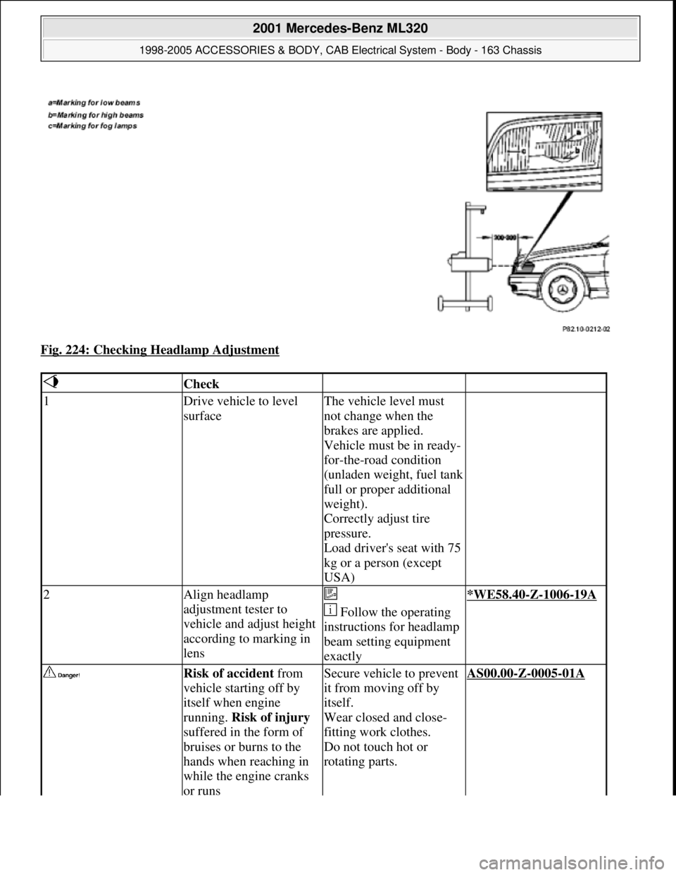
Fig. 224: Checking Headlamp Adjustment
Check
1Drive vehicle to level
surfaceThe vehicle level must
not change when the
brakes are applied.
Vehicle must be in ready-
for-the-road condition
(unladen weight, fuel tank
full or proper additional
weight).
Correctly adjust tire
pressure.
Load driver's seat with 75
kg or a person (except
USA)
2Align headlamp
adjustment tester to
vehicle and adjust height
according to marking in
lens
Follow the operating
instructions for headlamp
beam setting equipment
exactly*WE58.40-Z-1006-19A
Risk of accident from
vehicle starting off by
itself when engine
running. Risk of injury
suffered in the form of
bruises or burns to the
hands when reaching in
while the engine cranks
or runsSecure vehicle to prevent
it from moving off by
itself.
Wear closed and close-
fitting work clothes.
Do not touch hot or
rotating parts.AS00.00-Z-0005-01A
2001 Mercedes-Benz ML320
1998-2005 ACCESSORIES & BODY, CAB Electrical System - Body - 163 Chassis
me
Saturday, October 02, 2010 3:30:10 PMPage 324 © 2006 Mitchell Repair Information Company, LLC.