Page 1704 of 4133
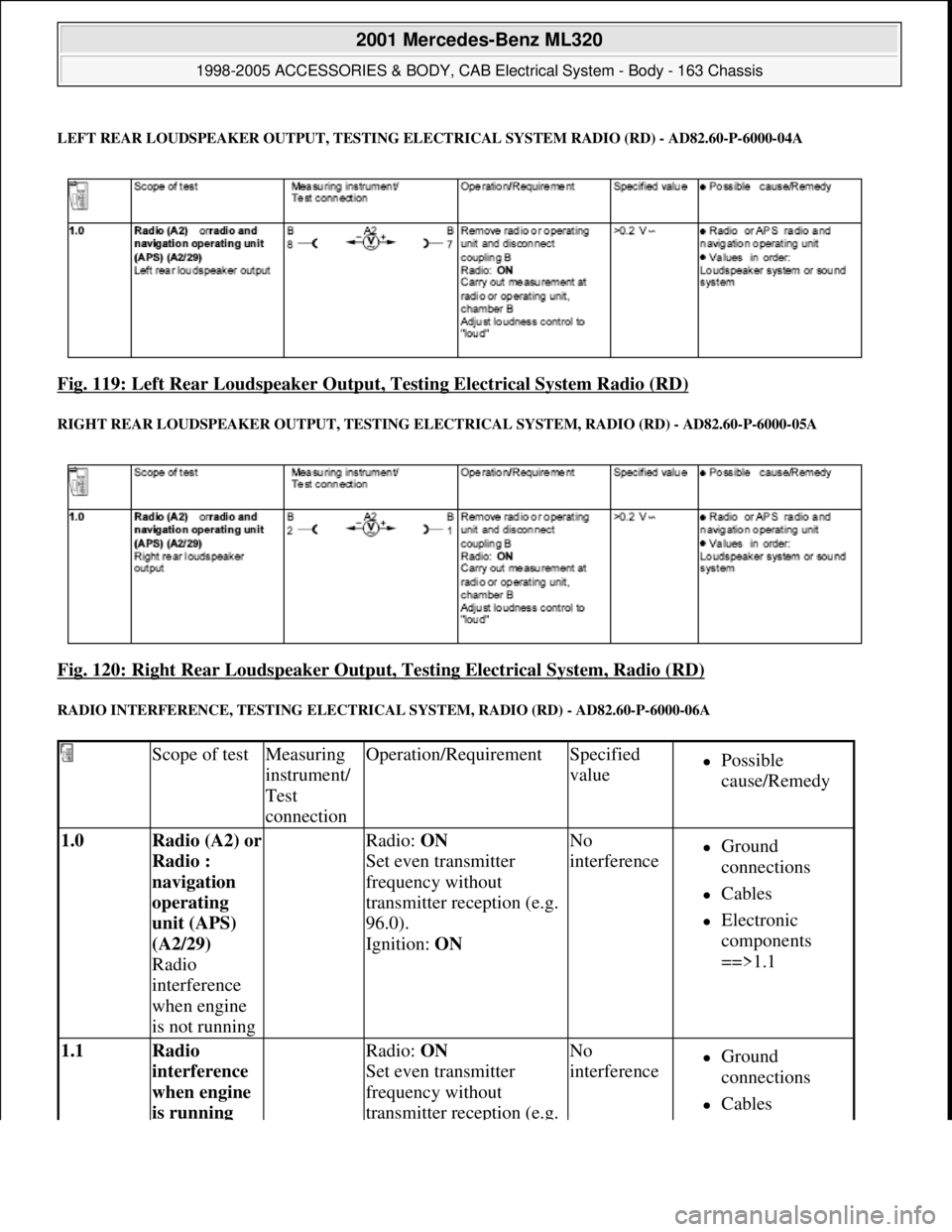
LEFT REAR LOUDSPEAKE R OUTPUT, TESTING ELEC TRICAL SYSTEM RADIO (RD) - AD82.60-P-6000-04A
Fig. 119: Left Rear Loudspeaker Output, Testing Electrical System Radio (RD)
RIGHT REAR LOUDSPEAKER OUTPUT, TESTING ELECTRICAL SYS TEM, RADIO (RD) - AD82.60-P-6000-05A
Fig. 120: Right Rear Loudspeaker Output , Testing Electrical System, Radio (RD)
RADIO INTERFERENCE, TESTING ELECTRICAL SYSTEM, RADIO (RD) - AD82.60-P-6000-06A
Scope of testMeasuring
instrument/
Test
connectionOperation/RequirementSpecified
valuePossible
cause/Remedy
1.0 Radio (A2) or
Radio :
navigation
operating
unit (APS)
(A2/29)
Radio
interference
when engine
is not running Radio: ON
Set even transmitter
frequency without
transmitter reception (e.g.
96.0).
Ignition: ON No
interferenceGround
connections
Cables
Electronic
components
==>1.1
1.1 Radio
interference
when engine
is running Radio: ON
Set even transmitter
frequency without
transmitter reception (e.g. No
interferenceGround
connections
Cables
2001 Mercedes-Benz ML320
1998-2005 ACCESSORIES & BODY, CAB Electr ical System - Body - 163 Chassis
me
Saturday, October 02, 2010 3:30:07 PMPage 209 © 2006 Mitchell Repair Information Company, LLC.
Page 1705 of 4133
RADIO RECEPTION, TESTING ELECTRICAL SYSTEM, RADIO (RD) - AD82.60-P-6000-07A
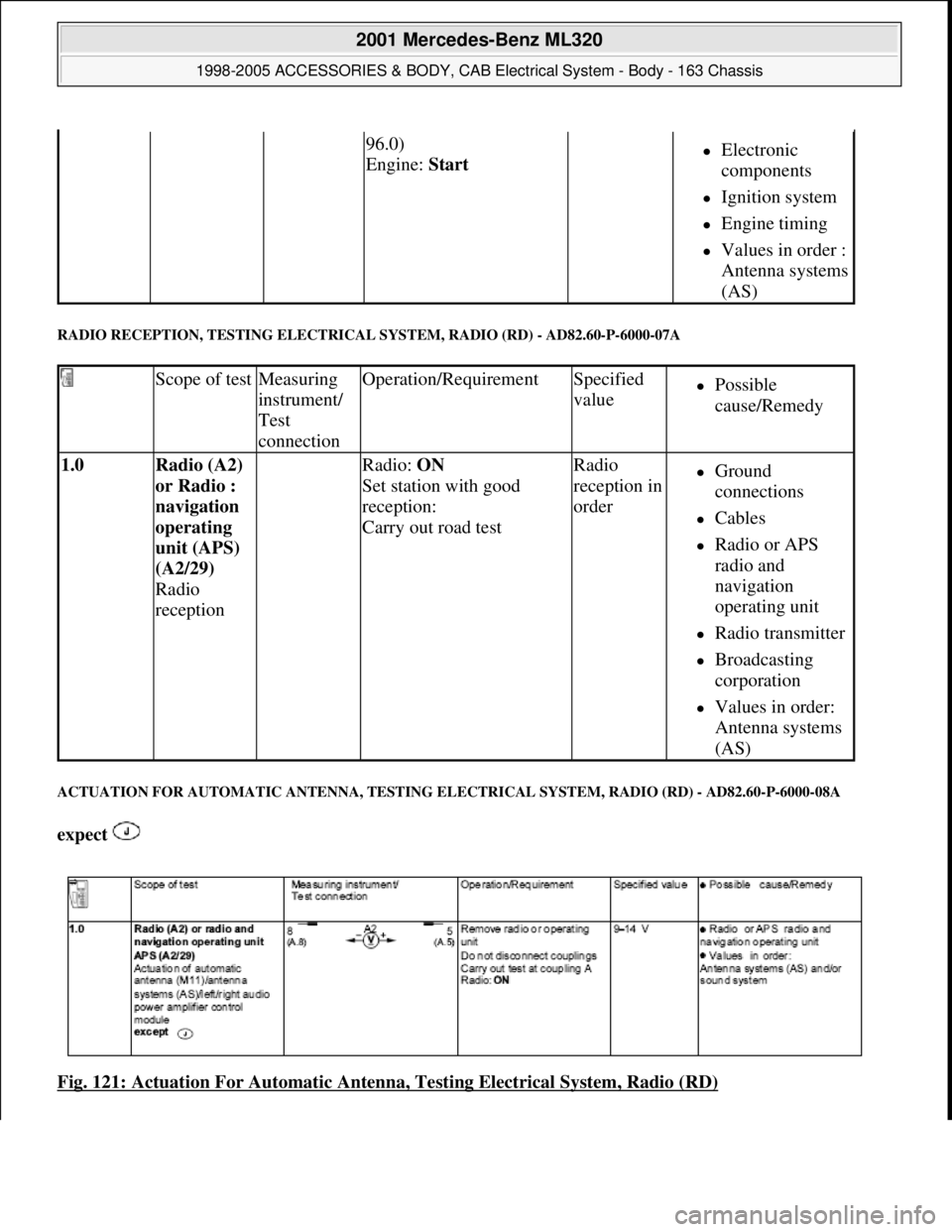
ACTUATION FOR AUTO MATIC ANTENNA, TESTING E LECTRICAL SYSTEM, RADIO (RD) - AD82.60-P-6000-08A
expect
Fig. 121: Actuation For Automatic Antenn a, Testing Electrical System, Radio (RD)
96.0)
Engine: Start Electronic
components
Ignition system
Engine timing
Values in order :
Antenna systems
(AS)
Scope of testMeasuring
instrument/
Test
connectionOperation/RequirementSpecified
valuePossible
cause/Remedy
1.0 Radio (A2)
or Radio :
navigation
operating
unit (APS)
(A2/29)
Radio
reception Radio: ON
Set station with good
reception:
Carry out road testRadio
reception in
orderGround
connections
Cables
Radio or APS
radio and
navigation
operating unit
Radio transmitter
Broadcasting
corporation
Values in order:
Antenna systems
(AS)
2001 Mercedes-Benz ML320
1998-2005 ACCESSORIES & BODY, CAB Electr ical System - Body - 163 Chassis
me
Saturday, October 02, 2010 3:30:07 PMPage 210 © 2006 Mitchell Repair Information Company, LLC.
Page 1758 of 4133
REMOVE/INSTALL HEADLAMP UNIT - AR82.10-P-4730GH
MODEL 163.113 /128 /136 /154 /157 /172 /174 /175
Fig. 163: Identifying Headlamp Unit Components
paneling (4)
2Unscrew screw (2) of turn
signal lamp (3) in the
exterior mirror paneling
(4)
3Remove turn signal lamp
(3) from the exterior
mirror paneling (4)
4Install in the reverse order
Remove/Install
1Open engine hood
2Unlock cover (1) at the
clip (arrow A) under the
lamp unit and unhook Installation: Lock
clip again.
3Unscrew screw (2)
4Unscrew nuts (3). Installation: Align
the lamp unit so that the
2001 Mercedes-Benz ML320
1998-2005 ACCESSORIES & BODY, CAB Electrical System - Body - 163 Chassis
me
Saturday, October 02, 2010 3:30:09 PMPage 263 © 2006 Mitchell Repair Information Company, LLC.
Page 1819 of 4133
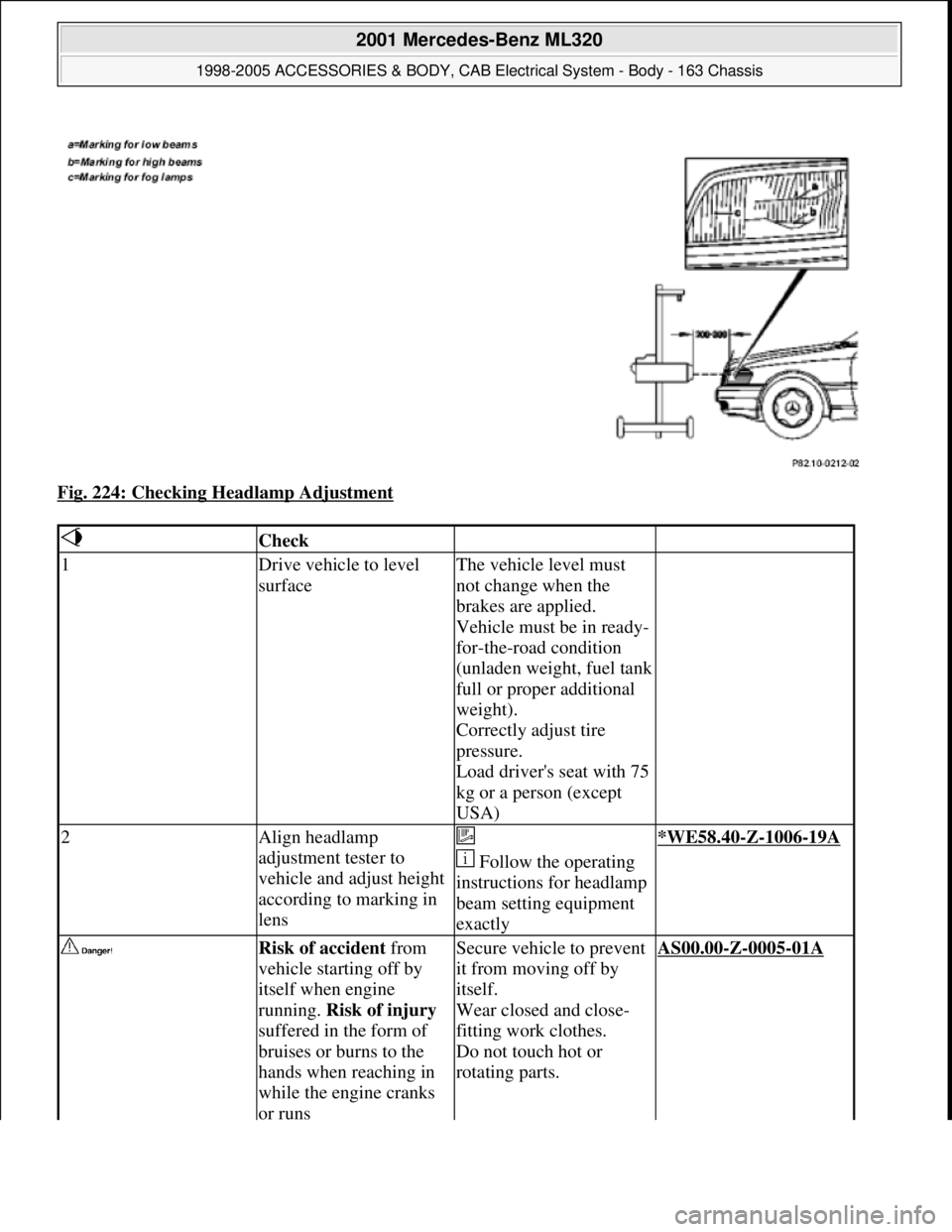
Fig. 224: Checking Headlamp Adjustment
Check
1Drive vehicle to level
surfaceThe vehicle level must
not change when the
brakes are applied.
Vehicle must be in ready-
for-the-road condition
(unladen weight, fuel tank
full or proper additional
weight).
Correctly adjust tire
pressure.
Load driver's seat with 75
kg or a person (except
USA)
2Align headlamp
adjustment tester to
vehicle and adjust height
according to marking in
lens
Follow the operating
instructions for headlamp
beam setting equipment
exactly*WE58.40-Z-1006-19A
Risk of accident from
vehicle starting off by
itself when engine
running. Risk of injury
suffered in the form of
bruises or burns to the
hands when reaching in
while the engine cranks
or runsSecure vehicle to prevent
it from moving off by
itself.
Wear closed and close-
fitting work clothes.
Do not touch hot or
rotating parts.AS00.00-Z-0005-01A
2001 Mercedes-Benz ML320
1998-2005 ACCESSORIES & BODY, CAB Electrical System - Body - 163 Chassis
me
Saturday, October 02, 2010 3:30:10 PMPage 324 © 2006 Mitchell Repair Information Company, LLC.
Page 1820 of 4133
Workshop equipment
WINDSHIELD WASHER - CHECKING AND CORRECTING FLUID LEVEL - AP82.35-P-8210GH
MODEL 163
Windshield washer fluid reservoir
Fig. 225: Locating Windshield Washer Fluid Reservoir
3Run engine and switch on
low beam
4Check headlamp range
control for proper
function(except USA)
The light beams from
both headlamps should
change uniformly
5Set headlamp range
control switch to position
0
6Check low beamsAdjust if necessary
(except USA)
Due to the common
reflector unit, the low
beams, high beams and
fog lamps are adjusted
simultaneously.
US version: ?
See "Owner's Manual"AP82.10-P-8260-01A
7Check high beam
adjustment AP82.10-P-8260-02A
8Check fog lamps AP82.10-P-8260-04A
WE58.40-Z-1006-19AHeadlamp adjustment testing unit
2001 Mercedes-Benz ML320
1998-2005 ACCESSORIES & BODY, CAB Electrical System - Body - 163 Chassis
me
Saturday, October 02, 2010 3:30:10 PMPage 325 © 2006 Mitchell Repair Information Company, LLC.
Page 1828 of 4133
Commercially available tools
Parts ordering notes
system antenna (GPS) on
roof
7Install adapter wiring
harness for vehicles with
engine 111 or up to 06/99
Vehicles with automatic
transmissionAN82.61-P-0001-01H
Vehicles with manual
transmissionAN82.61-P-0001-01I
8Retrofit diagnostic line On vehicles up to
06/99AN82.61-P-0001-03A
9Reassemble vehicle 5 to 1
10Enable equipment code See operating
instructions
11Start up auto-pilot system On vehicles with
sound system active
sound system when
performing diagnosis.AN82.61-P-1002-07B
*WH58.30
-Z-1036-13A
NumberDesignation
WH58.30-Z-1036-13AHandheld tester (HHT)651 100 01 99
Part no.DescriptionQuantity
B6 782 25 51Audio 30 APS radio1
KG82 (see EPC)GPS and telephone antenna1
KG82 (see EPC)Antenna lead from splitter to radio1
KG82 (see EPC)Adapter wiring harness (without
sound system) (vehicles with
M111 or up to 06.99)1
KG82 (see EPC)CAN bus wiring harness (vehicles
with M 111 or up to 06.99)1
KG82 (see EPC)CAN bus adapter (vehicles with M
111 or up to 06.99)1
KG82 (see EPC)Adapter wiring harness (with
sound system) (vehicles with M
111 or up to 06.99)1
A011 545 80 26Contact spring (radio) (on vehicles
up to 06.99)2
commercially availablegreen 0.5 mm lead2 2M
commercially availablegreen 0.5 mm lead 2 (diagnostic
lead) (on vehicles up to 06.99)2M
A012 545 39 26Contact spring (diagnostic socket) 1
2001 Mercedes-Benz ML320
1998-2005 ACCESSORIES & BODY, CAB Electrical System - Body - 163 Chassis
me
Saturday, October 02, 2010 3:30:10 PMPage 333 © 2006 Mitchell Repair Information Company, LLC.
Page 1829 of 4133
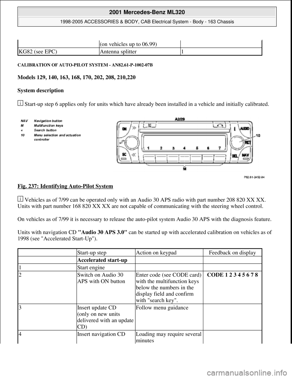
CALIBRATION OF AUTO-PILOT SYSTEM - AN82.61-P-1002-07B
Models 129, 140, 163, 168, 170, 202, 208, 210,220
System description
Start-up step 6 applies only for units which have already been installed in a vehicle and initially calibrated.
Fig. 237: Identifying Auto
-Pilot System
Vehicles as of 7/99 can be operated only with an Audio 30 APS radio with part number 208 820 XX XX.
Units with part number 168 820 XX XX are not capable of communicating with the steering wheel control.
On vehicles as of 7/99 it is necessary to release the auto-pilot system Audio 30 APS with the diagnosis feature.
Units with navigation CD "Audio 30 APS 3.0" can be started up with accelerated calibration on vehicles as of
1998 (see "Accelerated Start-Up").
(on vehicles up to 06.99)
KG82 (see EPC)Antenna splitter1
Start-up stepAction on keypadFeedback on display
Accelerated start-up
1Start engine
2Switch on Audio 30
APS with ON buttonEnter code (see CODE card)
with the multifunction keys
below the numbers in the
display field and confirm
with "search key".CODE 1 2 3 4 5 6 7 8
3Insert update CD
(only on new units
delivered with an update
CD)Follow menu guidance
4Insert navigation CDLoading may require several
minutes
2001 Mercedes-Benz ML320
1998-2005 ACCESSORIES & BODY, CAB Electrical System - Body - 163 Chassis
me
Saturday, October 02, 2010 3:30:11 PMPage 334 © 2006 Mitchell Repair Information Company, LLC.
Page 1901 of 4133
19. Install TrafficStar (1) ra dio and navigation system.
Fig. 334: Identifying GPS Antenna Connector And Sound Connector
CARRYING OUT START-UP AND FU NCTION CHECK - AZ82.61-P-0001-04A
Models 129, 140, 163, 168, 170, 202, 208, 210
System description
Fig. 335: Identifying Trafficstar Display Fi eld, Automatic Button And Mode Button
Step 5 for initial start-up only applies for equipment which has already been installed in a vehicle and on
which initial calibration has been performed.
Start-up step
Entry with TrafficStar
keysFeedback on TrafficStar display field
1Start engine
2Switch on TrafficStarEnter code (see CODE
card) with
multifunction buttons
below the numbers on
the display field.CODE 1 2 3 4 5 6 7 8
3Insert navigation CD
into TrafficStarLoading time approx. 1
min.
2001 Mercedes-Benz ML320
1998-2005 ACCESSORIES & BODY, CAB Electr ical System - Body - 163 Chassis
me
Saturday, October 02, 2010 3:30:12 PMPage 406 © 2006 Mitchell Repair Information Company, LLC.