Page 278 of 4133
228 First aid kit
Te ch n ica l
data Instruments
and controlsOperation DrivingInstrument
cluster displayPractical hintsCar care Index
First aid kit
All except model ML 55 AMG:
The first aid kit is located behind the cover in the left
rear cargo compartment trim panel.
Turn both handles (1) left and open cover.
Model ML 55 AMG:
The first aid kit is stored inside the spare wheel cover
located in the cargo compartment.
Open buckles and remove spare wheel cover,
see page 242.Fuses
Before replacing a blown fuse, determine the cause of
the short circuit.
Spare fuses and a special fuse puller are supplied inside
the fuse box cover. Observe amperage and color of fuse.
Always use a new fuse for replacement. Never attempt to
repair or bridge a blown fuse.
A fuse chart can be found inside the corresponding fuse
box cover.
Page 379 of 4133

module.
2. To install air bag module, reverse removal procedur e. Activate air bag system. Perform system operation
check to ensure system is functioning properly. See SYSTEM OPERATION CHECK
.
Removal & Installation (SLK 320)
1. Before proceeding, See AIR BAG SAFETY PRECAUTIONS . Disable air bag system. See
DISABLING & ACTIVATI NG AIR BAG SYSTEM
. Remove ignition key. Remove top section of
instrument panel. Fold vapor barrier toward front to reveal 2 screws. Disconnect passenger-side air bag
module connector. Remove 4 screws and passenger-side air bag module.
2. To install air bag module, reverse removal procedur e. Activate air bag system. Perform system operation
check to ensure system is functioning properly. See SYSTEM OPERATION CHECK
.
DIAGNOSTICS
Before proceeding, see AIR BAG SAFETY PRECAUTIONS
. The SRS control module is capable of
diagnosing air bag system components and ETR components. If a fault is detected by the SRS control module
or system is malfunctioning, SRS warning light will do one or more of the following:
SRS warning light goes out after 2 minutes. System fault is noted, however occupant protection is not
affected. See RETRIEVING FAULT CODES
.
SRS warning light illuminates cont inuously. System is faulty which may result in a non deployment or
false deployment. See RETRIEVING FAULT CODES
.
SRS warning light blinks continuous ly. Control module has been replaced without setting control module
parameters.
RETRIEVING FAULT CODES
1. Check vehicle fuses. Replace any blown fuses as nece ssary. Ensure vehicle battery voltage is 11 volts or
more. Ensure SRS warning light functions. Turn i gnition off. Connect Hand-Held Tester (HHT) (965 589
00 01) to Data Link Connector (DLC).
2. DLC is located in right rear corner of engine comp artment. It may be necessary to use Adapter (965 589
00 40 or 965 589 00 50) to connect HHT to DLC. Afte r HHT displays module number and version, press
return key to start diagnosis. Us ing HHT, follow HHT prompts to re trieve SRS fault codes. For SRS
control modules beginning with number 000, fault c ode 1 is valid. For SRS control modules beginning
with number 001, fault code 2 is valid. See Fig. 6
.
3. HHT will display a 3 digit fault code, and may display additional graphic information. This additional
graphic information will help in diagnosis of fault code. See Fig. 5
. During diagnosis HHT will display 4
different graphic displays info rming technician if a test passes or fail s, or if seat belt buckle is latched or
NOTE: After component replacement, perf
orm a system operation check to ensure
proper system operation. S ee SYSTEM OPERATION CHECK
.
NOTE: Fault codes may only be retrieved us ing Hand-Held Tester (965 589 00 01) and
Adapter (965 589 00 40 or 965 589 00 50).
2001 Mercedes-Benz ML320
2000-01 ACCESSORIES/SAFETY EQUIPMENT Merc edes-Benz - Air Bag Restraint Systems
me
Saturday, October 02, 2010 3:44:45 PMPage 15 © 2006 Mitchell Repair Information Company, LLC.
Page 695 of 4133
228
First aid kit
Te ch n ica l
data
Instruments
and controls Operation Driving
Instrument
cluster display Practical hints
Car care Index
First aid kit
All except model ML 55 AMG:
The first aid kit is located behind the cover in the left
rear cargo compartment trim panel.
Turn both handles (1) left and open cover.
Model ML 55 AMG:
The first aid kit is stored inside the spare wheel cover
located in the cargo compartment.
Open buckles and remove spare wheel cover,
see page 242. Fuses
Before replacing a blown fuse, determine the cause of
the short circuit.
Spare fuses and a special fuse puller are supplied inside
the fuse box cover. Observe amperage and color of fuse.
Always use a new fuse for replacement. Never attempt to
repair or bridge a blown fuse.
A fuse chart can be found inside the corresponding fuse
box cover.
Page 1881 of 4133
Fig. 301: Identifying Video/DVD Player, Striker And Locking Arm
RETROFIT VOLTAGE SUPPLY FOR CENTRAL INTERFACE MODULE - AZ82.60-P-0004-06A
Model 163.136 /154 /172 #A as of 145273, Models 163.136 /154 /172 #X as of 708319, Models
163.113/128 /157 /174 /175
1. Remove cover for fuse unit in right footwell.
Turn arresting mechanisms counterclockwise and move out cover to the rear.
2. Route plug for voltage supply (1) for the interface module of the fuse unit into the glove compartment
opening.
Guide cable under the right-hand instrument panel support (2).
View of left-hand steering installation
2001 Mercedes-Benz ML320
1998-2005 ACCESSORIES & BODY, CAB Electrical System - Body - 163 Chassis
me
Saturday, October 02, 2010 3:30:12 PMPage 386 © 2006 Mitchell Repair Information Company, LLC.
Page 1882 of 4133

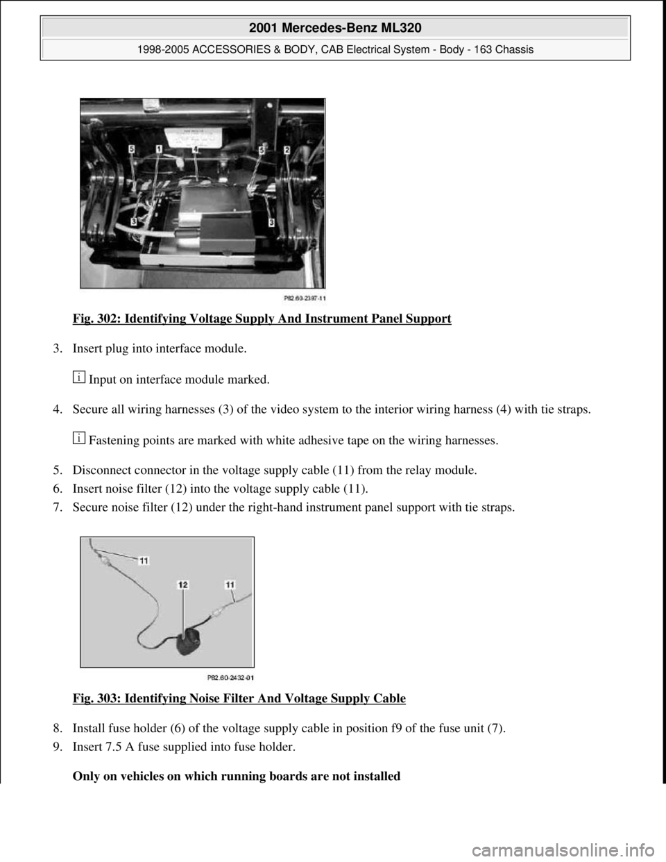
Fig. 302: Identifying Voltage Supply And Instrument Panel Support
3. Insert plug into interface module.
Input on interface module marked.
4. Secure all wiring harnesses (3) of the video system to the interior wiring harness (4) with tie straps.
Fastening points are marked with white adhesive tape on the wiring harnesses.
5. Disconnect connector in the voltage supply cable (11) from the relay module.
6. Insert noise filter (12) into the voltage supply cable (11).
7. Secure noise filter (12) under the right-hand instrument panel support with tie straps.
Fig. 303: Identifying Noise Filter And Voltage Supply Cable
8. Install fuse holder (6) of the voltage supply cable in position f9 of the fuse unit (7).
9. Insert 7.5 A fuse supplied into fuse holder.
Only on vehicles on which running boards are not installed
2001 Mercedes-Benz ML320
1998-2005 ACCESSORIES & BODY, CAB Electrical System - Body - 163 Chassis
me
Saturday, October 02, 2010 3:30:12 PMPage 387 © 2006 Mitchell Repair Information Company, LLC.
Page 1924 of 4133
Fig. 368: Identifying Lock Connector And Cable Terminals
12. Insert wiring harness (2) into instrument panel working from the glove compartment.
The tied-back part must be placed below the strut (arrows) at the glove compartment.
Fig. 369: Identifying Telephone Wiring Harness
13. Connect telephone wiring harness (2) to adapter wiring harness (9).
14. Check fuse (23) (a 10A fuse should be present).
2001 Mercedes-Benz ML320
1998-2005 ACCESSORIES & BODY, CAB Electrical System - Body - 163 Chassis
me
Saturday, October 02, 2010 3:30:13 PMPage 429 © 2006 Mitchell Repair Information Company, LLC.
Page 1929 of 4133
4. Unscrew sheet metal screws ( 30) from instrument panel.
5. Install mount (15) together with interface between mounting lugs (31) and (32) as shown in figure and
fasten with sheet metal screws (30).
6. Route connection plug for adapter wiring ha rness (D) upward into the radio recess.
Fig. 379: Identifying Mounting Lugs And Sheet Metal Screws
7. Connect portable cellular telephone wiring harn ess (2) to adapter wiring harness (9).
8. Check fuse (23) (a 10A fuse should be present).
Fig. 380: Identifying Fuse A nd Telephone Wiring Harness
9. Connect adapter wiring harness (9) to radio connector.
2001 Mercedes-Benz ML320
1998-2005 ACCESSORIES & BODY, CAB Electr ical System - Body - 163 Chassis
me
Saturday, October 02, 2010 3:30:13 PMPage 434 © 2006 Mitchell Repair Information Company, LLC.
Page 1931 of 4133
Fig. 383: Identifying Portable Cellular Telephone Wiring Harness And Components
7. Unscrew self-tapping screws (50) at instrument panel.
Insert mount with control modules from above through the radio opening.
8. Connect fiber optic cable.
9. Insert mount (15) with interface as shown in figure between the two mounting plates (51) and (52) and
attach with the self-tapping screws (50).
10. Route microphone connector (C) and adapter wiring harness connector (D) upward into radio shaft.
Fig. 384: Identifying Self
-Tapping Screws And Microphone Connector
11. Connect portable CTEL wiring harness (2) to adapter wiring harness (9).
12. Inspect fuse (23) (a 10A fuse must be fitted).
2001 Mercedes-Benz ML320
1998-2005 ACCESSORIES & BODY, CAB Electrical System - Body - 163 Chassis
me
Saturday, October 02, 2010 3:30:13 PMPage 436 © 2006 Mitchell Repair Information Company, LLC.