1997 MERCEDES-BENZ ML320 engine
[x] Cancel search: enginePage 1904 of 4133
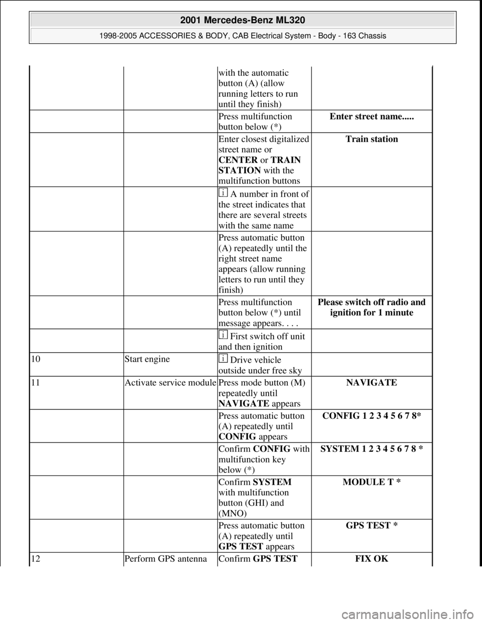
with the automatic
button (A) (allow
running letters to run
until they finish)
Press multifunction
button below (*)Enter street name.....
Enter closest digitalized
street name or
CENTER or TRAIN
STATION with the
multifunction buttonsTrain station
A number in front of
the street indicates that
there are several streets
with the same name
Press automatic button
(A) repeatedly until the
right street name
appears (allow running
letters to run until they
finish)
Press multifunction
button below (*) until
message appears. . . .Please switch off radio and
ignition for 1 minute
First switch off unit
and then ignition
10Start engine Drive vehicle
outside under free sky
11Activate service modulePress mode button (M)
repeatedly until
NAVIGATE appearsNAVIGATE
Press automatic button
(A) repeatedly until
CONFIG appearsCONFIG 1 2 3 4 5 6 7 8*
Confirm CONFIGwith
multifunction key
below (*)SYSTEM 1 2 3 4 5 6 7 8 *
Confirm SYSTEM
with multifunction
button (GHI) and
(MNO)MODULE T *
Press automatic button
(A) repeatedly until
GPS TEST appearsGPS TEST *
12Perform GPS antenna Confirm GPS TEST FIX OK
2001 Mercedes-Benz ML320
1998-2005 ACCESSORIES & BODY, CAB Electrical System - Body - 163 Chassis
me
Saturday, October 02, 2010 3:30:13 PMPage 409 © 2006 Mitchell Repair Information Company, LLC.
Page 1913 of 4133
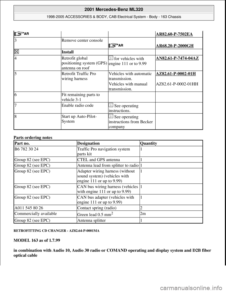
Parts ordering notes
RETROFITTING CD CHANGER - AZ82.64-P-0001MA
MODEL 163 as of 1.7.99
in combination with Audio 10, Audio 30 radio or COMAND operating and display system and D2B fiber
optical cable
AR82.60-P-7502EA
3Remove center console
AR68.20-P-2000GH
Install
4Retrofit global
positioning system (GPS)
antenna on roof for vehicles with
engine 111 or to 9.99AN82.61-P-7474-04AZ
5Retrofit Traffic Pro
wiring harnessVehicles with automatic
transmission.AZ82.61-P-0002-01H
Vehicles with manual
transmission.AZ82.61-P-0002-01HH
6Fit remaining parts to
vehicle 3-1
7Enable radio code See operating
instructions.
8Start up Auto-Pilot-
System See operating
instructions from Becker
company
Part no.DesignationQuantity
B6 782 30 24Traffic Pro navigation system
parts kit1
Group 82 (see EPC)CTEL and GPS antenna1
Group 82 (see EPC)Antenna lead from splitter to radio1
Group 82 (see EPC)Adapter wiring harness (without
sound system) (vehicles with
engine 111 or up to 9.99)1
Group 82 (see EPC)CAN bus wiring harness (vehicles
with engine 111 or up to 9.99)1
Group 82 (see EPC)CAN bus adapter (vehicles with
engine 111 or up to 9.99)1
A011 545 80 26Contact spring (radio)2
Commercially availableGreen lead 0.5 mm2 2m
Group 82 (see EPC)Antenna splitter1
2001 Mercedes-Benz ML320
1998-2005 ACCESSORIES & BODY, CAB Electrical System - Body - 163 Chassis
me
Saturday, October 02, 2010 3:30:13 PMPage 418 © 2006 Mitchell Repair Information Company, LLC.
Page 1964 of 4133
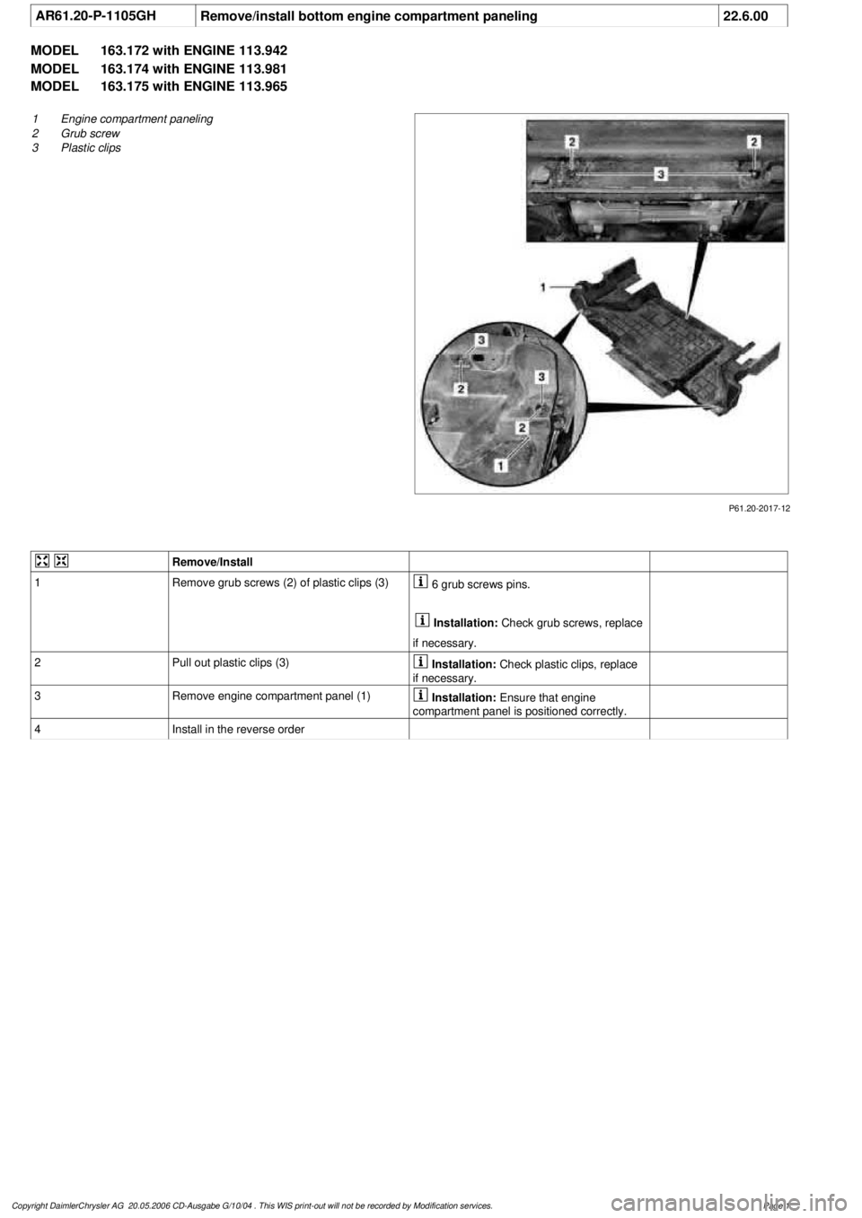
AR61.20-P-1105GH
Remove/install bottom engine compartment paneling
22.6.00
MODEL
163.172 with ENGINE 113.942
MODEL
163.174 with ENGINE 113.981
MODEL
163.175 with ENGINE 113.965
P61.20-2017-12
1
Engine compartment paneling
2
Grub screw
3
Plastic clips
Remove/Install
1
Remove grub screws (2) of plastic clips (3)
6 grub screws pins.
Installation:
Check grub screws, replace
if necessary.
2
Pull out plastic clips (3)
Installation:
Check plastic clips, replace
if necessary.
3
Remove engine compartment panel (1)
Installation:
Ensure that engine
compartment panel is positioned correctly.
4
Install in the reverse order
Copyright DaimlerChrysler AG 20.05.2006 CD-Ausgabe G/10/04 . This WIS print-out will not be recorde
d by Modification services.
Page 1
Page 1970 of 4133
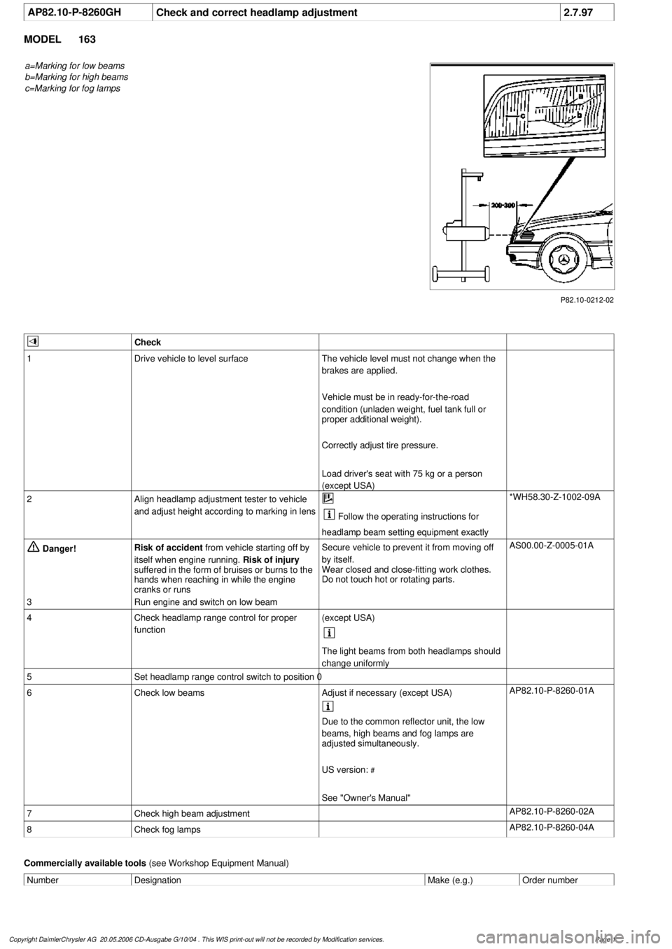
AP82.10-P-8260GH
Check and correct headlamp adjustment
2.7.97
MODEL
163
a=Marking for low beams
b=Marking for high beams
c=Marking for fog lamps
P82.10-0212-02
Check
1
Drive vehicle to level surface
The vehicle level must not change when the
brakes are applied.
Vehicle must be in ready-for-the-road
condition (unladen weight, fuel tank full or
proper additional weight).
Correctly adjust tire pressure.
Load driver's seat with 75 kg or a person
(except USA)
2
Align headlamp adjustment tester to vehicle
and adjust height according to marking in lens
Follow the operating instructions for
headlamp beam setting equipment exactly
*WH58.30-Z-1002-09A
Danger!
Risk of accident
from vehicle starting off by
itself when engine running.
Risk of injury
suffered in the form of bruises or burns to the
hands when reaching in while the engine
cranks or runs
Secure vehicle to prevent it from moving off
by itself.
Wear closed and close-fitting work clothes.
Do not touch hot or rotating parts.
AS00.00-Z-0005-01A
3
Run engine and switch on low beam
4
Check headlamp range control for proper
function
(except USA)
The light beams from both headlamps should
change uniformly
5
Set headlamp range control switch to position 0
6
Check low beams
Adjust if necessary (except USA)
AP82.10-P-8260-01A
Due to the common reflector unit, the low
beams, high beams and fog lamps are
adjusted simultaneously.
US version:
#
See "Owner's Manual"
7
Check high beam adjustment
AP82.10-P-8260-02A
8
Check fog lamps
AP82.10-P-8260-04A
Commercially available tools
(see Workshop Equipment Manual)
Number
Designation
Make (e.g.)
Order number
Copyright DaimlerChrysler AG 20.05.2006 CD-Ausgabe G/10/04 . This WIS print-out will not be recorde
d by Modification services.
Page 1
Page 2030 of 4133
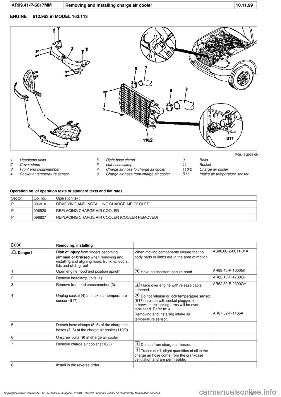
AR09.41-P-6817MM
Removing and installing charge air cooler
10.11.99
ENGINE
612.963 in MODEL 163.113
P09.41-2024-09
1
Headlamp units
2
Cover strips
3
Front end crossmember
4
Socket at temperature sensor
9
Bolts
11
Socket
110/2
Charge air cooler
B17
Intake air temperature sensor
5
Right hose clamp
6
Left hose clamp
7
Charge air hose to charge air cooler
8
Charge air hose from charge air cooler
Operation no. of operation texts or standard texts and flat rates
Sector
Op. no.
Operation text
P
096810
REMOVING AND INSTALLING CHARGE AIR COOLER
P
096820
REPLACING CHARGE AIR COOLER
P
096827
REPLACING CHARGE AIR COOLER (COOLER REMOVED)
Removing, installing
Danger!
Risk of injury
from fingers becoming
jammed or bruised
when removing and
installing and aligning hood, trunk lid, doors,
lids and sliding roof
When moving components ensure that no
body parts or limbs are in the area of motion.
AS00.00-Z-0011-01A
1
Open engine hood and position upright
Have an assistant secure hood
AR88.40-P-1000GI
2
Remove headlamp units (1)
AR82.10-P-4730GH
3
Remove front end crossmember (3)
Place over engine with release cable
attached.
AR62.30-P-2300GH
4
Unplug socket (4) at intake air temperature
sensor (B17)
Do not release or lock temperature sensor
(B17) in place with socket plugged in
otherwise the locking arms will be over-
tensioned. Refer to:
#
Removing and installing intake air
temperature sensor.
AR07.52-P-1465A
5
Detach hose clamps (5, 6) of the charge air
hoses (7, 8) at the charge air cooler (110/2)
6
Unscrew bolts (9) at charge air cooler
7
Remove charge air cooler (110/2)
Detach from charge air hoses.
Traces of oil, slight quantities of oil in the
charge air hose come from the crankcase
ventilation and are permissible.
8
Install in the reverse order
Copyright DaimlerChrysler AG 12.05.2006 CD-Ausgabe G/10/04 . This WIS print-out will not be recorde
d by Modification services.
Page 1
Page 2032 of 4133
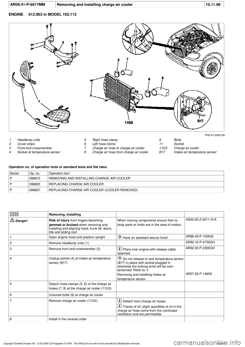
AR09.41-P-6817MM
Removing and installing charge air cooler
10.11.99
ENGINE
612.963 in MODEL 163.113
P09.41-2024-09
1
Headlamp units
2
Cover strips
3
Front end crossmember
4
Socket at temperature sensor
9
Bolts
11
Socket
110/2
Charge air cooler
B17
Intake air temperature sensor
5
Right hose clamp
6
Left hose clamp
7
Charge air hose to charge air cooler
8
Charge air hose from charge air cooler
Operation no. of operation texts or standard texts and flat rates
Sector
Op. no.
Operation text
P
096810
REMOVING AND INSTALLING CHARGE AIR COOLER
P
096820
REPLACING CHARGE AIR COOLER
P
096827
REPLACING CHARGE AIR COOLER (COOLER REMOVED)
Removing, installing
Danger!
Risk of injury
from fingers becoming
jammed or bruised
when removing and
installing and aligning hood, trunk lid, doors,
lids and sliding roof
When moving components ensure that no
body parts or limbs are in the area of motion.
AS00.00-Z-0011-01A
1
Open engine hood and position upright
Have an assistant secure hood
AR88.40-P-1000GI
2
Remove headlamp units (1)
AR82.10-P-4730GH
3
Remove front end crossmember (3)
Place over engine with release cable
attached.
AR62.30-P-2300GH
4
Unplug socket (4) at intake air temperature
sensor (B17)
Do not release or lock temperature sensor
(B17) in place with socket plugged in
otherwise the locking arms will be over-
tensioned. Refer to:
#
Removing and installing intake air
temperature sensor.
AR07.52-P-1465A
5
Detach hose clamps (5, 6) of the charge air
hoses (7, 8) at the charge air cooler (110/2)
6
Unscrew bolts (9) at charge air cooler
7
Remove charge air cooler (110/2)
Detach from charge air hoses.
Traces of oil, slight quantities of oil in the
charge air hose come from the crankcase
ventilation and are permissible.
8
Install in the reverse order
Copyright DaimlerChrysler AG 12.05.2006 CD-Ausgabe G/10/04 . This WIS print-out will not be recorde
d by Modification services.
Page 1
Page 2034 of 4133
GF54.30-P-3007A
Charge indicator lamp, exterior lamp failure
24.10.96
MODEL
129, 140 as of 1.6.96,
163, 168, 170,
202 as of 1.8.96,
208 up to 31.7.99,
210 as of 1.6.96 up to 30.6.99
P54.30-0517-06
Terminal 61 is used for the generator
indicator lamp. When the ignition is
On
the excitation voltage is applied to it and
the generator voltage when the engine is
running.
However, a terminal is required for some
systems (e.g. exterior lamp indicator) which
D
is exactly at ground potential (low level),
when the engine is not running with the
ignition
On
D
is exactly at least 10.5 V (high level),
when the voltage at terminal 61
exceeds a particular voltage or the
engine speed exceeds a particular
threshold (480 rpm).
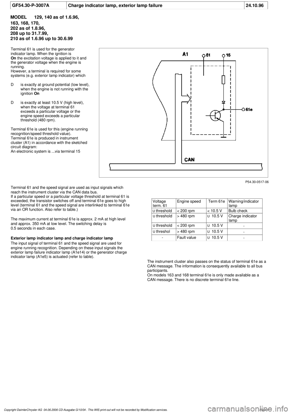
Terminal 61e is used for this (engine running
recognition/speed threshold value).
Terminal 61e is produced in instrument
cluster (A1) in accordance with the sketched
circuit diagram:
An electronic system is ...via terminal 15
Terminal 61 and the speed signal are used as input signals which
reach the instrument cluster via the CAN data bus.
If a particular speed or a particular voltage threshold at terminal 61 is
exceeded, the transistor switches off and terminal 61e goes to high
level (terminal 61 and the speed signal are interlinked to terminal 61e
via an OR function. Also refer to table.)
The maximum current at terminal 61e is approx. 2 mA at high level
and approx. 350 mA at low level. The switching delay is
0.5 seconds in each case.
Exterior lamp indicator lamp and charge indicator lamp
The input signal of terminal 61 and the speed signal are used for
engine running recognition. Depending on these input signals the
exterior lamp failure indicator lamp (A1e14) or the generator charge
indicator lamp (A1e5) is actuated (refer to table).
The instrument cluster also passes on the status of terminal 61e as a
CAN message. The information is consequently available to all bus
participants.
On models 163 and 168 terminal 61e is only made available as a
CAN message. There is no discrete terminal 61e line.
Voltage
term. 61
Engine speed
Term 61e
Warning/indicator
lamp
U
threshold
< 200 rpm
< 10.5 V
Bulb check
U
threshold
> 480 rpm
U
10.5 V
Charge indicator
lamp
U
threshold
< 200 rpm
U
10.5 V
-
U
threshol
> 480 rpm
U
10.5 V
-
-
Fault value
U
10.5 V
-
Copyright DaimlerChrysler AG 04.06.2006 CD-Ausgabe G/10/04 . This WIS print-out will not be recorde
d by Modification services.
Page 1
Page 2035 of 4133
2001-04 STARTING & CHARGING SYSTEMS
Generators & Regulators - 163 Chassis
IDENTIFICATION
CHASSIS & ENGINE IDENTIFICATION
DESCRIPTION
Bosch generators are available in various amp ratings depending on engine application. Voltage regulators are
transistorized and internal to generator. See GENERATOR APPLICATION
table.
GENERATOR APPLICATION
ADJUSTMENTS
DRIVE BELT ROUTING
For drive belt routing, see Fig. 1 . WARNING:Vehicles are equipped with air bag supplemental restraint system. Before
attempting any repairs involving steering column, instrument panel or
related components, see SERVICE PRECAUTIONS (or AIR BAG SAFETY
PRECAUTIONS) and DISABLING & ACTIVATING AIR BAG SYSTEM in
appropriate AIR BAG RESTRAINT SYSTEMS article.
NOTE: When the battery is disconnected, vehicle computer and memory system may
lose data. Driveability problems may exist until computer systems have
completed a relearn cycle.
Model (Year)ChassisEngine
ML55 AMG (2001-03)163.174113.981
ML320 (2001-02)163.154112.942
ML350 (2003-04)163.157112.970
ML430 (2001)163.172113.942
ML500 (2002-04)163.175113.965
ApplicationAmp Rating
V6115
V8150
NOTE: Vehicles have automatic belt tensioners. No adjustment is necessary.
2001 Mercedes-Benz ML320
2001-04 STARTING & CHARGING SYSTEMS Generators & Regulators - 163 Chassis
2001 Mercedes-Benz ML320
2001-04 STARTING & CHARGING SYSTEMS Generators & Regulators - 163 Chassis
me
Saturday, October 02, 2010 3:20:31 PMPage 1 © 2006 Mitchell Repair Information Company, LLC.
me
Saturday, October 02, 2010 3:20:35 PMPage 1 © 2006 Mitchell Repair Information Company, LLC.