1997 MERCEDES-BENZ ML320 engine
[x] Cancel search: enginePage 1397 of 4133
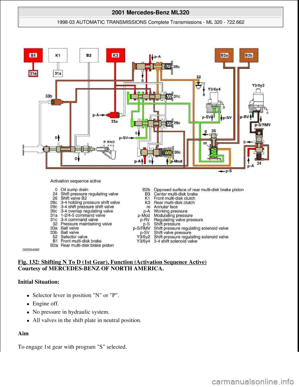
Fig. 132: Shifting N To D (1st Gear), Function (Activation Sequence Active)
Courtesy of MERCEDES-BENZ OF NORTH AMERICA.
Initial Situation:
Selector lever in position "N" or "P".
Engine off.
No pressure in hydraulic system.
All valves in the shift plate in neutral position.
Aim
To en
gage 1st gear with program "S" selected.
2001 Mercedes-Benz ML320
1998-03 AUTOMATIC TRANSMISSIONS Complete Transmissions - ML 320 - 722.662
me
Saturday, October 02, 2010 3:15:28 PMPage 228 © 2006 Mitchell Repair Information Company, LLC.
Page 1398 of 4133
Shifting 2nd gear with program selection "W" or "C" (depending on the production period).
Function
Start engine -
The working pressure (p-A) is formed, reaches via the holding pressure 2-3 shift valve, the command valve 2-3
and ball valve (33a) to the rear multi-disc clutch (K3) and via the command valve 3-4 (31c) to the end face of
the shift pressure 3-4 (29c) shift valve. The 3-4 shift pressure shift valve (29c) is moved against the force of the
spring towards the right. At the same time the 3-4 solenoid valve (Y3/6y4) is energized.
The ECT control unit (N15/3) monitors the engagement process via the reduced speed of the drive shaft as the
frictional connection of the rear multi-disc brake increases. When the speed drops to the specified level, the
ECT control module (N15/3) shuts off the power to the 3-4 shift solenoid valve (Y3/6y4). The spring chamber
of the shift valve B2 (26) is depressurized and switches downward. As a result the line to the opposed surface of
the rear multi-disc brake piston (B2b) is connected to the pressure maintaining valve (32). The pressure on the
opposed surface of the rear multi-disc brake piston (B2b) reduces to a residual pressure.
The 3-4 command valve (31c) moves to the left. The working pressure (p-A) reaches via the holding pressure
shift valve 3-4 (28c) and the command valve 3-4 (31c) to the piston of the rear multi-disc brake (B2a).
The activation sequence is complete; 1st gear is engaged (See Fig. 130
.
As a result shift valve pressure (p-SV) reaches the spring chamber of the shift valve B2 (26) and the end face of
the command valve 3-4 (31c).
The shift valve B2 (26) is held in the upper position and the 3-4 command valve (31c) switches towards the
right.
The working pressure (p-a) is replaced by the shift valve pressure (p-SV) at the end face of the shift pressure 3-
4 shift valve (See Fig. 131
).
Move Selector Lever From "N" To "D"
The selector lever (52) opens the shift pressure (p-S) feed connection from the ball valve (33b) with the shift
valve B2 (26). In the upper position of the shift valve B2 (26) shift pressure (p-S) reaches behind (p-S) the
piston of the multi-disc brake (B2a) and simultaneously to the opposed surface of the rear multi-disc brake
piston (B2b).
The rear multi-disc brake begins to close. See Fig. 132
.
The pressure on the opposed surface of the piston of the rear multi-disc brake (B2b) causes a gentle engagement
of the rear multi-disc brake.
Move Selector Lever From "N" To "R"
The selector valve (52) opens the connection of the feed of shift pressure (p-S) with the center multi-disc brake
2001 Mercedes-Benz ML320
1998-03 AUTOMATIC TRANSMISSIONS Complete Transmissions - ML 320 - 722.662
me
Saturday, October 02, 2010 3:15:28 PMPage 229 © 2006 Mitchell Repair Information Company, LLC.
Page 1405 of 4133
See MODULATING PRESSURE, FUNCTION
.
Shift Valve Pressure, Function
See SHIFT VALVE PRESSURE, FUNCTION
.
Lubricating Pressure, Function
See LUBRICATING PRESSURE, FUNCTION
.
Regulating Valve Pressure, Function
See REGULATING VALVE PRESSURE, FUNCTION
.
Limp-Home Mode, Function
Operation
In order to ensure a safe driving state and to prevent damage to the automatic transmission, the ECT control
module (N15/3) switches to limp-home mode in the event of critical faults. A fault code assigned to the fault is
stored in memory.
All solenoid and regulating valves are thus de-energized.
Effect
The gear last engaged remains engaged.
The modulating pressure and shift pressure rise to the maximum levels.
The torque converter lockup clutch is switched off.
In order to preserve the operability of the vehicle to some extent, the hydraulic control can be used to engage
2nd gear or reverse:
Stop Vehicle
Switch Off Engine
Move Selector Lever To "P"
Wait At Least 10 Seconds
Start Engine
Move Selector Lever To "D": 2Nd Gear
Move Selector Lever To "R"
The limp-home function remains active until the fault is rectified or the stored fault code is erased. Sporadic
faults can be reset via ignition OFF/ON.
2001 Mercedes-Benz ML320
1998-03 AUTOMATIC TRANSMISSIONS Complete Transmissions - ML 320 - 722.662
me
Saturday, October 02, 2010 3:15:29 PMPage 236 © 2006 Mitchell Repair Information Company, LLC.
Page 1410 of 4133
See LOCATION/TASK/FUNCTION OF COMMAND VALVE
.
Selector Valve, Location/Task
See SELECTOR VALVE, LOCATION/TASK
.
Location/Task/Design/Function Of Oil Pump
See LOCATION/TASK/DESIGN/FUNCTION OF OIL PUMP
.
Modulating Pressure, Function
Operation
The modulating pressure influences the size of the working pressure and determines together with the shift
pressure the pressure regulated at the overlap regulating valve.
The modulating pressure is regulated at the modulating pressure regulating solenoid (Y3/6y1), which is under
regulating valve pressure. The modulating pressure via variable and relative to the engine load.
Modulating Pressure Regulating Solenoid Valve, Location/Task/Design/Function
See MODULATING PRESSURE REGULATING SOLENOID VALVE,
LOCATION/TASK/DESIGN/FUNCTION.
Working Pressure Regulating Valve, Location/Task/Function
See WORKING PRESSURE REGULATING VALVE, LOCATION/TASK/FUNCTION
.
Overlap Regulating Valve, Location/Task/Function
See NOVERLAP REGULATING VALVE, LOCATION/TASK/FUNCTION
.
Upshift/Downshift Solenoid Valve, Location/Task/Design/Function
See UPSHIFT/DOWNSHIFT SOLENOID VALVE, LOCATION/TASK/DESIGN/FUNCTION
Shift Pressure Control Solenoid Valve, Location/Task/Design/Function
See SHIFT PRESSURE REGULATING SOLENOID VALVE,
LOCATION/TASK/DESIGN/FUNCTION.
Location/Task/Design/Function Of PWM Solenoid Valve, Torque Converter Lockup Clutch
See LOCATION/TASK/DESIGN/FUNCTION OF PWM SOLENOID VALVE, TORQUE
CONVERTER LOCKUP CLUTCH.
2001 Mercedes-Benz ML320
1998-03 AUTOMATIC TRANSMISSIONS Complete Transmissions - ML 320 - 722.662
me
Saturday, October 02, 2010 3:15:29 PMPage 241 © 2006 Mitchell Repair Information Company, LLC.
Page 1424 of 4133
Fig. 142: Manual Drive Mode Selection, Function
Courtesy of MERCEDES-BENZ OF NORTH AMERICA.
Operation
With the selector lever on the floor shift it is possible to adapt the automatic gearshift sequence to suit specific
operating conditions. Although the selector lever position can be changed the forward gears while driving, the
electronic transmission control (ETC) prevents over-revving of the engine. See Fig. 142
.
Floor Shift, Location/Task/Design/Function
See .
Reverse Lamp Switch, Location/Task/Function
See REVERSE LAMP SWITCH, LOCATION/TASK/FUNCTION
.
Shift Detent Mechanism, Location/Task/Design/Function
See SHIFT DETENT MECHANISM, LOCATION/TASK/DESIGN/FUNCTION (WITHOUT
TOUCH SHIFT).
D-4 Shift Isolating Mechanism, Location/Task/Design/Function
See D
-4 SHIFT ISOLATING MECHANISM, LOCATION/TASK/DESIGN/FUNCTION.
Location/Task/Design/Function Of R/P Lock
See LOCATION/TASK/DESIGN/FUNCTION OF R/P LOCK (WITHOUT TOUCH SHIFT)
.
Position Sensor, Location/Task/Function
See POSITION SENSOR, LOCATION/TASK/FUNCTION
.
Transmission Range Recognition Switch, Location/Task/Design/Function
See TRANSMISSION RANGE RECOGNITION SWITCH,
LOCATION/TASK/DESIGN/FUNCTION.
ETC Control Module, Location/Task
See ETC CONTROL UNIT, LOCATION/TASK
.
Floor Shift, Location/Task/Design/Function
2001 Mercedes-Benz ML320
1998-03 AUTOMATIC TRANSMISSIONS Complete Transmissions - ML 320 - 722.662
me
Saturday, October 02, 2010 3:15:29 PMPage 255 © 2006 Mitchell Repair Information Company, LLC.
Page 1430 of 4133
Fig. 146: Manual Drive Mode Selection, Function
Courtesy of MERCEDES-BENZ OF NORTH AMERICA.
Operation
With the selector lever on the floor shift it is possible to adapt the automatic gearshift sequence to suit specific
operating conditions. See Fig. 146
. Although the selector lever position can be changed in the forward gears
while driving, the electronic transmission control (ETC) prevents over-revving of the engine.
Floor Shift, Location/Task/Design/Function
See FLOOR SHIFT, LOCATION/TASK/DESIGN/FUNCTION
.
Shift Detent Mechanism, Location/Task/Design/Function
See SHIFT DETENT MECHANISM, LOCATION/TASK/DESIGN/FUNCTION
Location/Task/Design/Function Of R/P Lock
See LOCATION/TASK/DESIGN/FUNCTION OF R/P LOCK
.
Position Display, Location/Task
See POSITION DISPLAY, LOCATION/TASK
.
ETC Control Module, Location/Task
See ETC CONTROL UNIT, LOCATION/TASK
.
Control Module For Electronic Selector Lever Module, Location/Task/Design
See .
Floor Shift, Location/Task/Design/Function
TRANSMISSION with touch shift.
2001 Mercedes-Benz ML320
1998-03 AUTOMATIC TRANSMISSIONS Complete Transmissions - ML 320 - 722.662
me
Saturday, October 02, 2010 3:15:29 PMPage 261 © 2006 Mitchell Repair Information Company, LLC.
Page 1446 of 4133
Task
The ETC control module (N15/3) determines the instantaneous operating condition of the vehicle and controls
all gearshift sequences taking into account the ease of shifting and the driving situation. This involves receiving,
converting and transmitting various digital and analog signals. See Fig. 157
.
It receives operating data in the form of input signals from:
Starter Lock-Out Contact (Y3/6S1)
RPM Sensor 2 (Y3/6N2)
RPM Sensor 3 (Y3/6N3)
Transmission Oil Temperature Sensor (Y3/6B1)
In addition there is a connection via the engine compartment bus to the:
Instrument Cluster (A1)
ME-SFI Control Module (N3/10) or CDI Control Module (N3/9)
The solenoid valves for the modulating and shift pressure and for the gear changes are actuated by the ETC
control module (N15/3).
The pressure required is calculated from all input signals, adjusted to the torque to be transferred. The following
information from other systems is then processed:
ME-SFI Control Module (N3/10) or CDI Control Module (N3/9):
Engine Torque
Engine Speed
Accelerator Pedal Position
Gear Shift
Engine Status
Electronic selector lever module control module (N15/5):
Kickdown Switch (S16/6)
Selector Lever Position P/N
Traction system control module (N47):
Transmission Ratio
Speeds
Instrument cluster (A1):
2001 Mercedes-Benz ML320
1998-03 AUTOMATIC TRANSMISSIONS Complete Transmissions - ML 320 - 722.662
me
Saturday, October 02, 2010 3:15:29 PMPage 277 © 2006 Mitchell Repair Information Company, LLC.
Page 1449 of 4133
The ETC control module (N15/3) determines the instantaneous operating condition of the vehicle and controls
all gearshift sequences taking into account the ease of shifting and the driving situation. See Fig. 158
. This
involves receiving , converting and transmitting various digital and analog signals.
Input Signals:
Starter Lock-Out Contact (Y3/6S1)
RPM Sensor 2 (Y3/6N2)
RPM Sensor 3 (Y3/6N3)
Transmission Oil Temperature Sensor (Y3/6B1)
Kickdown Switch (S16/6)
Gear Recognition Switch (S16/10)
Output signals:
Reverse/Parking Lock Valve
Input And Output Signals:
Datalink Connector (X11/4)
In addition there is a connection via the engine compartment bus to the:
ME-SFI Control Module (N3/10) or CDI Control Module (N3/9)
Traction System Control Module (N47)
Transfer Case Control Module (N78)
The solenoid valves for the modulating and shift pressure and for the gear changes are actuated by the ETC
control module (N15/3). The pressure required is calculated from all input signals, adjusted to the torque to be
transferred.
The following information from other systems is then processed:
ME-SFI Control Module (N3/10) or CDI Control Module (N3/9)
Reverse And Parking Lock Solenoids (Y66/1)
Selector Lever Position (P/N) to the Engine Control Module (ME-SFI) (N3/10) (only on detection of the
selector lever position "P" or "N" on the transmission range recognition switch (S16/10) and at the starter
interlock contact (Y3/6s1)).
Traction System Control Module (N47):
Wheel Speeds
Gear Shift
Traction Status
2001 Mercedes-Benz ML320
1998-03 AUTOMATIC TRANSMISSIONS Complete Transmissions - ML 320 - 722.662
me
Saturday, October 02, 2010 3:15:29 PMPage 280 © 2006 Mitchell Repair Information Company, LLC.