Page 1183 of 4133
Fig. 13: Disconnecting Ground Lead From Battery
Courtesy of MERCEDES-BENZ OF NORTH AMERICA.
1.1 - Open engine hood.
2 - Disconnect ground cable of battery. See Fig. 13
.
NOTE: Model Series 163.
NOTE: To protect against unwanted contact of the disconnected ground line (1)
W16/4 insulate cable lug of the ground line.
2001 Mercedes-Benz ML320
1998-03 AUTOMATIC TRANSMISSIONS Complete Transmissions - ML 320 - 722.662
me
Saturday, October 02, 2010 3:15:25 PMPage 14 © 2006 Mitchell Repair Information Company, LLC.
Page 1202 of 4133
The parking lock gear and drive flange are connected to the output shaft by gearing.
Freewheels F1 and F2 optimize shifting. The front freewheel (F1) rests against the stator shaft extension on the
transmission side and connects the sun gear of the front planetary gear set tot the transmission housing in the
locking direction.
The torque converter housing and transmission housing are made of a metal alloy. They are bolted together and
centered via the outer multiple-disc carrier of the multiple-disc brake B1. A coated intermediate panel seals the
two components.
The oil pump and outer multiple-disc carrier of the front multiple-disc brake are bolted to the converter housing.
The mechanical part consists of the propeller shaft, output shaft, a sun gear shaft and three planetary gearsets
which are coupled together.
In transmissions for powerful engines, the planetary gearsets have 4 planetary gears, while for less powerful
engines the front and rear planetary gear system has three planetary gear wheels. The stator shaft is pressed into
this and is secured against turning by a spline.
The rear freewheel (F2) connects the sun gear of the center planetary gear set to the sun gear of the rear
planetary gearset in the locking direction.
The electrohydraulic control unit consists of the shift plate made of light alloy for hydraulic control and an
electronic control unit.
The electrical control unit consists of a supporting body made of plastic in which the electrical components are
combined. The shell is screwed tot he shift plate. Conductor tracks which are integrated into the shell, connect
the electric components to a plug connector. This 13-pin plug connector forms the connection with the vehicle-
side wiring harness and with the ETC 5 (Electronic Transmission Control) control module (N15/5) via a
bayonet lock.
Automatic Transmission, Location Of Mechanical Parts
See AUTOMATIC TRANSMISSION, LOCATION OF MECHANICAL PARTS
.
Automatic Transmission, Location Of Electric/Electronic Components
See AUTOMATIC TRANSMISSION, LOCATION OF ELECTRIC/ELECTRONIC
COMPONENTS.
Automatic Transmission, Location Of Hydraulic Components
See AUTOMATIC TRANSMISSION, POSITION OF HYDRAULIC COMPONENTS
.
Automatic Transmission, Location Of Components, Floor Shift
See AUTOMATIC TRANSMISSION, LOCATION OF COMPONENTS, FLOOR SHIFT
.
2001 Mercedes-Benz ML320
1998-03 AUTOMATIC TRANSMISSIONS Complete Transmissions - ML 320 - 722.662
me
Saturday, October 02, 2010 3:15:26 PMPage 33 © 2006 Mitchell Repair Information Company, LLC.
Page 1210 of 4133
The parking lock mechanism consists of the parking lock gear (4), the parking lock pawl (43), the cone (42)
with spring (41) and the guide sleeve (4). See Fig. 22
. The parking shift lock is actuated by the locking pawl
(39) and link rod (37) via the detent plate (38).
Park Pawl, Function
See Fig. 22.
Operation
In selector lever position "P", the cone (42) slides between the parking lock pawl (43) and the guide sleeve (40).
The parking lock pawl (43) is therefore pushed against the parking lock gear (4). If the tooth of the parking lock
pawl (43) does not engage in a tooth space when the vehicle is stationary, but rather touches a tooth of the
parking lock gear (4), the cone (42) is pre-tensioned by the spring (41) and positioned ready for operation. If the
parking lock gear (4) continues to turn, the parking lock pawl (43) engages in the next tooth space.
To prevent damage due to misuse, the intervals between the tooth gaps are such that the park detent (43) can
only engage when the vehicle is stationary or crawling at low speed. If the vehicle rolls faster, the shape of the
teeth prevents the parking lock pawl (43) from engaging.
AUTOMATIC TRANSMISSION MODEL AND COMPONENT INSTALLATION SURVEY AS-BUILT CONFIGURATION
Transmission 722.6 In Model 163
Component survey for automatic transmission. See COMPONENT SURVEY FOR AUTOMATIC
TRANSMISSION MODEL 163.
COMPONENT SURVEY FOR AUTOMATIC TRANSMISSION MODEL 163
SURVEY OF SYSTEM COMPONENTS, AUTOMATIC TRANSMISSION, LOCATION/TASK/DESIGN/FUNCTION
(WITHOUT TOUCH SHIFT)
Starter Lock-Out Contact, Location/Task/Design/Function
Sales DesignationModelEngineTransmission
ML 230163.136111.977722.660
ML 270 CDI163.113612.963722.661
ML 320163.154112.942722.662
ML 350163.157112.970722.674
ML 400163.128628.963722.673
ML 400 CDI163.128628.963722.666
ML 430163.172113.942722.663
ML 500163.175113.965722.666
ML 55 AMG163.174113.981722.666
NOTE: Transmission Without Touch Shift 722.6 In Model 163
2001 Mercedes-Benz ML320
1998-03 AUTOMATIC TRANSMISSIONS Complete Transmissions - ML 320 - 722.662
me
Saturday, October 02, 2010 3:15:26 PMPage 41 © 2006 Mitchell Repair Information Company, LLC.
Page 1232 of 4133
vehicle is stationary and the engine is idling, boosts the engine torque and provides infinitely variable
engine speed and torque matching when moving off.
Torque Converter, Design
The impeller (P) is connected to the engine, the turbine wheel (T) is connected to the transmission input
shaft.
The stator (L) is connected to the transmission housing via a freewheel and the stator shaft (8).
Torque Converter, Function
See TORQUE CONVERTER, FUNCTION
.
Torque Converter, Function
Due to the effect of centrifugal force, the blades of the impeller (P) pump the oil outwards to the turbine wheel
(T), causing it to rotate. See Fig. 31
. The turbine wheel blades direct the oil onto the blades of the stator, which
in turn push the oil back to the impeller (P) (arrow). This diversion at the stator (L), which is supported against
the transmission housing via the freewheel, produces and increase in torque. At the maximum speed difference
between the impeller and the turbine wheel (T), the torque conversion achieves its maximum value at a factor of
1.8 to 2.0, dropping to a torque ratio of 1:1 as the speeds converge. From this operating state onwards, also
referred to as the coupling point, the stator (l) rotates with the impeller (P) and the turbine wheel (T).
Efficiencies of up to approximately 98% are achieved in the coupling range.
The oil in the torque converter is constantly being replaced so that the heat produced in the operating phase can
be dissipated via the transmission oil cooler.
2001 Mercedes-Benz ML320
1998-03 AUTOMATIC TRANSMISSIONS Complete Transmissions - ML 320 - 722.662
me
Saturday, October 02, 2010 3:15:26 PMPage 63 © 2006 Mitchell Repair Information Company, LLC.
Page 1236 of 4133
Wheel Speed Sensor, Location
RPM sensors 2 and 3 (Y3/6n2 and Y3/6n3) are permanently connected with the supporting body of the
electrical control unit (Y3/6) via contact tongues. See Fig. 32
.
Wheel Speed Sensor,
The signals from the RPM sensors 2 3 (Y3/6n2, Y3/6n3) are recorded in the ETC control module (N15/3)
together with the wheel and engine speeds and other information, and are the input signals for the
electronic control system.
Wheel Speed Sensor, Function
See SPEED SENSOR, FUNCTION
.
Speed Sensor, Function
2001 Mercedes-Benz ML320
1998-03 AUTOMATIC TRANSMISSIONS Complete Transmissions - ML 320 - 722.662
me
Saturday, October 02, 2010 3:15:26 PMPage 67 © 2006 Mitchell Repair Information Company, LLC.
Page 1264 of 4133
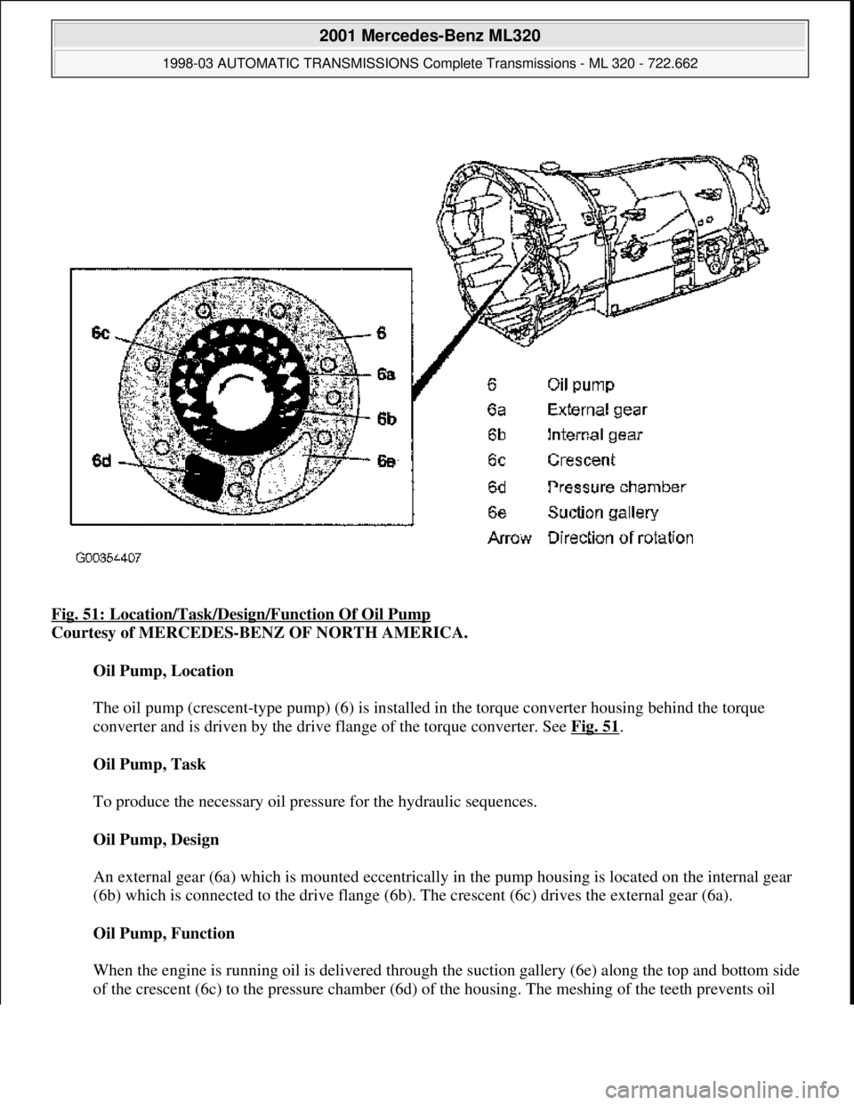
Fig. 51: Location/Task/Desi gn/Function Of Oil Pump
Courtesy of MERCEDES-BENZ OF NORTH AMERICA.
Oil Pump, Location
The oil pump (crescent-type pump) (6) is installed in the torque converter housing behind the torque
converter and is driven by the drive flange of the torque converter. See Fig. 51
.
Oil Pump, Task
To produce the necessary oil pressure for the hydraulic sequences.
Oil Pump, Design
An external gear (6a) which is m ounted eccentrically in the pump housi ng is located on the internal gear
(6b) which is connected to the drive flange (6b). The crescent (6c) drives the external gear (6a).
Oil Pump, Function
When the engine is running oil is delivered through th e suction gallery (6e) along the top and bottom side
of the crescent (6c) to the pr essure chamber (6d) of the housin
g. The meshing of the teeth prevents oil
2001 Mercedes-Benz ML320
1998-03 AUTOMATIC TRANSMI SSIONS Complete Transmissions - ML 320 - 722.662
me
Saturday, October 02, 2010 3:15:26 PMPage 95 © 2006 Mitchell Repair Information Company, LLC.
Page 1306 of 4133
Overlap Regulating Valve, Function
Operation - During the shift phase the pressure in the disengaging shift actuator is controlled depending on the
engine load (modulating pressure (p-Mod)) and the pressure in the engaging shift actuator. The regulated
pressure is inversely proportional to the transfer capacity of the activating shift actuator (regulated overlap). See
Fig. 78
.
2001 Mercedes-Benz ML320
1998-03 AUTOMATIC TRANSMISSIONS Complete Transmissions - ML 320 - 722.662
me
Saturday, October 02, 2010 3:15:27 PMPage 137 © 2006 Mitchell Repair Information Company, LLC.
Page 1333 of 4133
Task - The ETC control module (N15/3) determines the instantaneous operating condition of the vehicle and
controls all gearshift sequences taking into account the ease of shifting and the driving situation. This involves
receiving, converting and transmitting various digital and analog signals. See Fig. 96
.
It receives operating data in the form of input signals from:
Starter Lock-Out Contact (Y3/6S1)
RPM Sensor 2 (Y3/6N2)
RPM Sensor 3 (Y3/6n3)
Transmission Oil Temperature Sensor (Y3/6B1)
In addition there is a connection via the engine compartment bus to the:
Instrument Cluster (A1)
ME-SFI Control Module (N3/10) or CDI Control Module (N3/9)
The solenoid valves for the modulating and shift pressure and for the gear changes are actuated by the ETC
control module (N15/3).
The pressure required is calculated from all input signals, adjusted to the torque to be transferred. The following
information from other systems is then processed.
ME-SFI Control Module (N3/10) or CDI Control Module (N3/9):
Engine Torque
Engine Speed
Accelerator Pedal Position
Gear Shift
Engine Status
Electronic Selector Lever Module Control Module (N15/5):
Kickdown Switch (S16/6)
Selector Lever Position P/N
Traction System Control Module (N47):
Transmission Ratio
Speeds
Instrument Cluster (A1):
Selector Lever Position/Shift Range
2001 Mercedes-Benz ML320
1998-03 AUTOMATIC TRANSMISSIONS Complete Transmissions - ML 320 - 722.662
me
Saturday, October 02, 2010 3:15:27 PMPage 164 © 2006 Mitchell Repair Information Company, LLC.