Page 1519 of 4133
Fog and other lighting influences, e.g., due to oncoming traffic, do not have any effect on the automatic
driving light actuation.
Automatic driving light actuation when starting a journey and during it
Automatic driving light actuation with driving lights is only possible when the engine is running (circuit
61 ON).
When the engine is switched off and the electronic starter switch is in position "2" (circuit 15 ON) only
the side lamps and the license plate lamps are actuated.
Driving light actuation is disabled as soon as one of the basic prerequisites changes, e.g. when changing
from darkness to daylight after driving through a tunnel.
Automatic driving light actuation at the end of a journey or in darkness
After switching off the engine (circuit 61 OFF) and when the electronic starter switch is in position
"2" (circuit 15 ON), only the side lamps and the license plate lamps remain on.
The exterior lighting is switched off as of key position "1" (circuit 15R).
DAYTIME RUNNING LIGHT ACTUATION, FUNCTION - GF82.10-P-3005GH
MODEL 163 as of 01.09.01
With daytime running lamps the low beam, the side lamps and the license plate lamps are switched on if the
engine is running (there are national variants).
Function prerequisites:
Circuit 61 "ON"
In "AUTO" position of the exterior lamp switch daytime running lamps and automatic driving lights are
OR gated, i.e. depending on the prerequisites daytime running lamps or automatic driving lights are switched
on.
For the daytime running lamp conditions, there is no difference between the positions "0" and "AUTO" of
the exterior lamp switch.
Corresponding to the national legislation, the daytime running lamps can be coded in different variants via
Star Diagnosis.
Canada and USA
Table of contents,
function description for
exterior lighting GF82.10-P-0999A
2001 Mercedes-Benz ML320
1998-2005 ACCESSORIES & BODY, CAB Electrical System - Body - 163 Chassis
me
Saturday, October 02, 2010 3:30:04 PMPage 24 © 2006 Mitchell Repair Information Company, LLC.
Page 1539 of 4133
The actual frequency is also a factor of the vehicle's speed of travel (see chart below).
The wiper is turned off by reactivating the wiper/washer switch.
The start of each wipe cycle is synchronized with the front wiper system.
Networking
Rain sensor (B38) and reverse signals are fed to the All Activity Module (AAM) (N10) via the engine
compartment CAN.
The settings of the rear wiper/washer switch (S78) are read directly by the All Activity Module (AAM)
(N10) .
The tailgate wiper motor unit (M6/4) is controlled directly by the All Activity Module (AAM, N10) .
The tailgate wiper motor unit (M6/4) comprises a relay and a cam-operated switch in addition to the
actual motor.
WINDSHIELD INTERMITTENT WIPE, FUNCTION - GF82.30-P-3003GH
MODEL 163
Function sequence
The interval wiping function is switched on to position (i) with the combination switch.
The input (pin A8) of the all-activity module (AAM, N10) is connected to c. 15 R .
The AAM immediately actuates the front wiper motor relay (F1k17) for max. 2 s. In wiper stage 1 power is
supplied to the wiper motor (M6/1) b
y the relay (pin a).
Vehicle speed Under 50
km/hVehicle speed 50 to 100
km/hVehicle speed 100 km/h
and higher
Frequency of Rear wiperOne twelfth of front
wiper frequencyOne tenth of front wiper
frequencyOne sixth of front wiper
frequency
Rear Wiper/Washer Switch -
Location/Task/ Design/Function GF82.30-P-
4105GH
All Activity Module -
Location/Task/Design/ Function GF54.21-P-
4100GK
Tailgate Wiper Motor -
Location/Task/Design/ Function GF82.30-P-
4105GH
Rain Sensor -
Location/Task/Design/FunctionVehicles with code
345a (rain sensor)
onlyGF82.30-P-
4103GH
2001 Mercedes-Benz ML320
1998-2005 ACCESSORIES & BODY, CAB Electrical System - Body - 163 Chassis
me
Saturday, October 02, 2010 3:30:04 PMPage 44 © 2006 Mitchell Repair Information Company, LLC.
Page 1543 of 4133
How it works
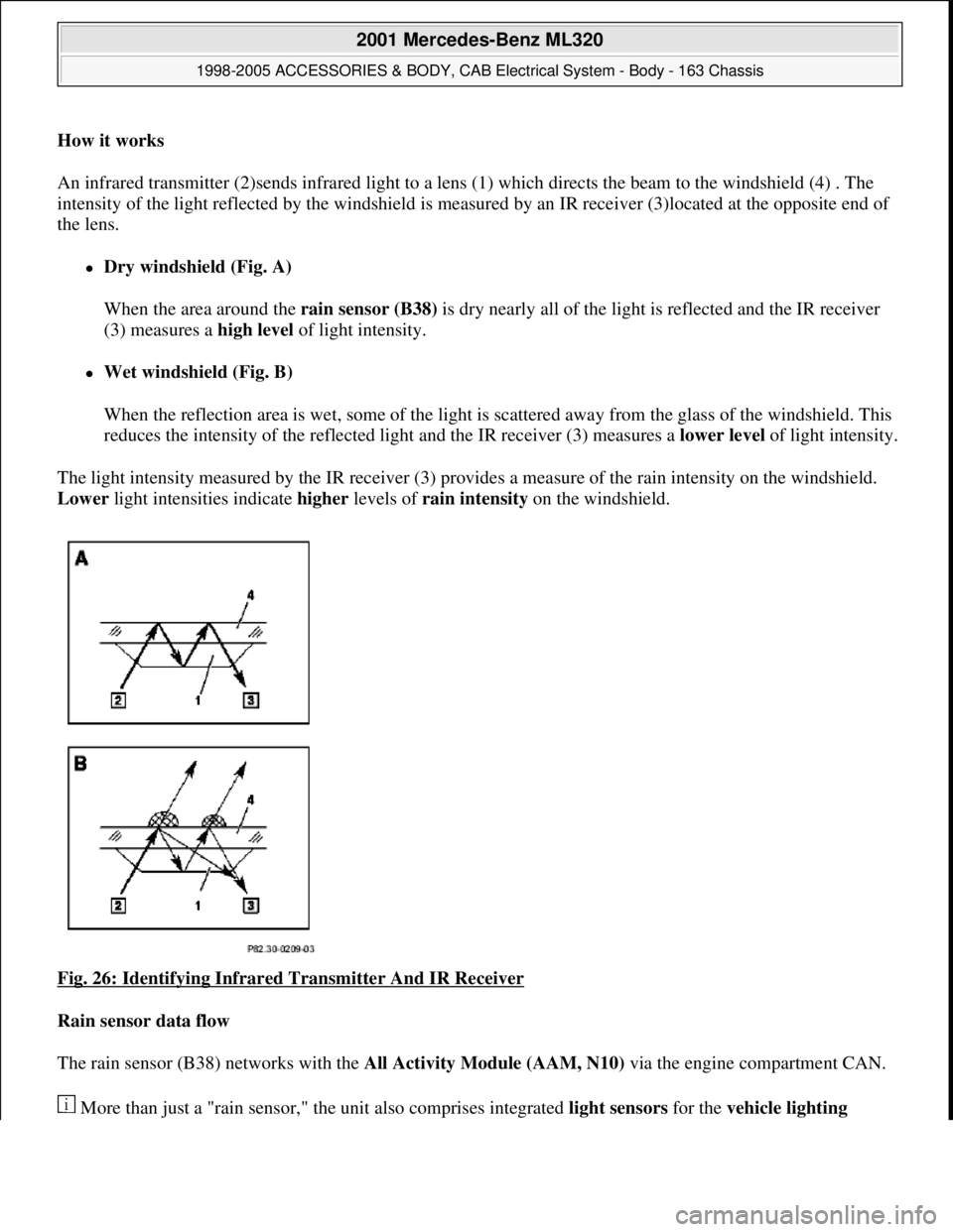
An infrared transmitter (2)sends infrared light to a lens (1) which directs the beam to the windshield (4) . The
intensity of the light reflected by the windshield is measured by an IR receiver (3)located at the opposite end of
the lens.
Dry windshield (Fig. A)
When the area around the rain sensor (B38) is dry nearly all of the light is reflected and the IR receiver
(3) measures a high level of light intensity.
Wet windshield (Fig. B)
When the reflection area is wet, some of the light is scattered away from the glass of the windshield. This
reduces the intensity of the reflected light and the IR receiver (3) measures a lower level of light intensity.
The light intensity measured by the IR receiver (3) provides a measure of the rain intensity on the windshield.
Lower light intensities indicate higher levels of rain intensity on the windshield.
Fig. 26: Identifying Infrared Transmitter And IR Receiver
Rain sensor data flow
The rain sensor (B38) networks with the All Activity Module (AAM, N10) via the engine compartment CAN.
More than
just a "rain sensor," the unit also comprises integrated light sensors for the vehicle lighting
2001 Mercedes-Benz ML320
1998-2005 ACCESSORIES & BODY, CAB Electrical System - Body - 163 Chassis
me
Saturday, October 02, 2010 3:30:04 PMPage 48 © 2006 Mitchell Repair Information Company, LLC.
Page 1544 of 4133
system . Data from the light sensors is also sent to the All Activity Module (AAM, N10) via the engine
compartment CAN.
Power supply
Power is supplied to the rain sensor (B38) via KI. 15 so that these functions are available only when the ignition
is on.
RAIN SENSOR - LOCATION/TASK/DESIGN/FUNCTION - GF82.30-P-4103GH
MODEL 163 with code 345a Rain sensor
Fig. 27: Identifying Rain Sensor Location
Rain Sensor - LocationThe rain sensor (B38) is
adhered to the inside
surface of the windshield.
Rain Sensor - TaskThe rain sensor (B38)
assesses the rain
intensity on the
windshield and
automatically adjusts the
intermittent wiper speed.
In addition, light sensors
gauge ambient light
2001 Mercedes-Benz ML320
1998-2005 ACCESSORIES & BODY, CAB Electrical System - Body - 163 Chassis
me
Saturday, October 02, 2010 3:30:05 PMPage 49 © 2006 Mitchell Repair Information Company, LLC.
Page 1545 of 4133
WIPER MOTOR, FUNCTION - GF82.30-P-4104-01GH
The wiper arm can be driven by the motor with two speeds. The motor runs at high or low speed depending on
brush voltage present.
The cam switch switches circuit 31b from circuit 15 to circuit 31 when the windshield wiper runs through the
park position.
WIPER MOTOR, DESIGN - GF82.30-P-4104-02GH
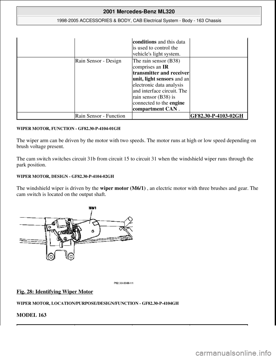
The windshield wiper is driven by the wiper motor (M6/1) , an electric motor with three brushes and gear. The
cam switch is located on the output shaft.
Fig. 28: Identifying Wiper Motor
WIPER MOTOR, LOCATION/PURPOSE/DESIGN/FUNCTION - GF82.30-P-4104GH
MODEL 163
conditions and this data
is used to control the
vehicle's light system.
Rain Sensor - DesignThe rain sensor (B38)
comprises an IR
transmitter and receiver
unit, light sensorsand an
electronic data analysis
and interface circuit. The
rain sensor (B38) is
connected to the engine
compartment CAN .
Rain Sensor - Function GF82.30-P-4103-02GH
2001 Mercedes-Benz ML320
1998-2005 ACCESSORIES & BODY, CAB Electrical System - Body - 163 Chassis
me
Saturday, October 02, 2010 3:30:05 PMPage 50 © 2006 Mitchell Repair Information Company, LLC.
Page 1664 of 4133
![MERCEDES-BENZ ML320 1997 Complete Repair Manual MODEL 163 with CODE (259) Radio Premium with Bose sound system
Parts ordering notes
PROGRAM CHANGE ALTHOUGH RDS [RADIO DATA SYSTEM] AND REGIONALIZATION ARE SWITCHED ON -
AF82.60-P-1062A
MODEL 129, MERCEDES-BENZ ML320 1997 Complete Repair Manual MODEL 163 with CODE (259) Radio Premium with Bose sound system
Parts ordering notes
PROGRAM CHANGE ALTHOUGH RDS [RADIO DATA SYSTEM] AND REGIONALIZATION ARE SWITCHED ON -
AF82.60-P-1062A
MODEL 129,](/manual-img/4/57305/w960_57305-1663.png)
MODEL 163 with CODE (259) Radio Premium with Bose sound system
Parts ordering notes
PROGRAM CHANGE ALTHOUGH RDS [RADIO DATA SYSTEM] AND REGIONALIZATION ARE SWITCHED ON -
AF82.60-P-1062A
MODEL 129, 140, 163, 168, 170, 171, 202, 203, 208, 209, 210, 211, 215, 220, 230, 463 with RDS radio
Damage codeCauseRemedy
Speaker wires picking up
interference noise from
surrounding wiring1 Remove radioAR82.60-P-7502EA
2 Remove upper center
console storage
compartment
3 Remove lower dash
panel below steering
columnAR68.10-P-1500GH
4 Install sound system
jumper harness
AF82.60-P-1010-01AG
5 Reinstall in opposite
order
Part no.DesignationQuantity
163 540 98 05Jumper harness for Bose sound
system1
Damage codeCauseRemedy
Station change without
obvious cause.
Some radio stations
which had originally
transmitted regional
identification have been
transmitting the RDS
signals without regional
identification for some
time.
Without regional
identification it is no
longer possible to
separate stations with the
same station name which
transmit different
programs.1 Point out the facts to
the customer.
Do not replace any
devices, state of the art
engineering.
2001 Mercedes-Benz ML320
1998-2005 ACCESSORIES & BODY, CAB Electrical System - Body - 163 Chassis
me
Saturday, October 02, 2010 3:30:06 PMPage 169 © 2006 Mitchell Repair Information Company, LLC.
Page 1674 of 4133
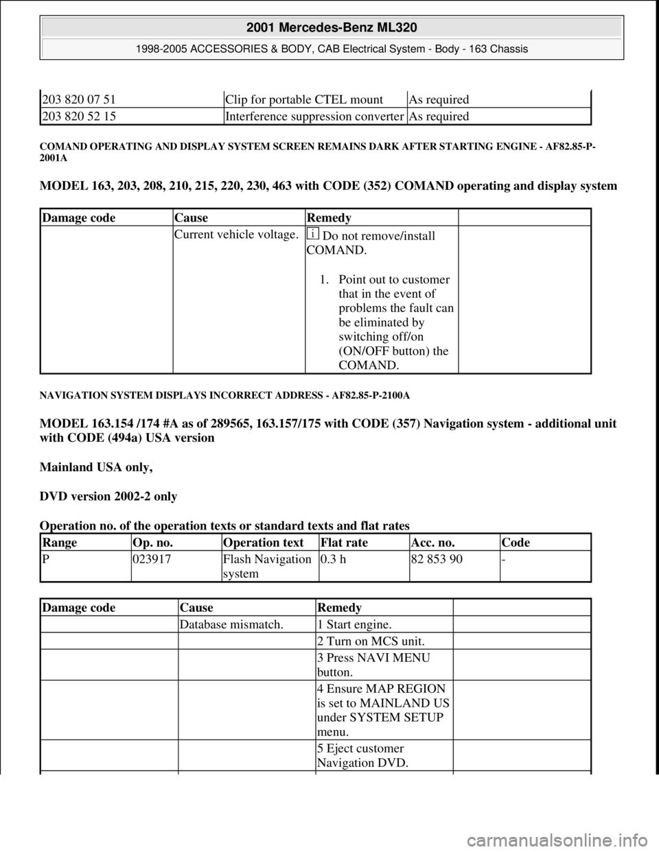
COMAND OPERATING AND DISPLAY SYSTEM SCREEN REMAINS DARK AFTER STARTING ENGINE - AF82.85-P-
2001A
MODEL 163, 203, 208, 210, 215, 220, 230, 463 with CODE (352) COMAND operating and display system
NAVIGATION SYSTEM DISPLAYS INCORRECT ADDRESS - AF82.85-P-2100A
MODEL 163.154 /174 #A as of 289565, 163.157/175 with CODE (357) Navigation system - additional unit
with CODE (494a) USA version
Mainland USA only,
DVD version 2002-2 only
Operation no. of the operation texts or standard texts and flat rates
203 820 07 51Clip for portable CTEL mountAs required
203 820 52 15Interference suppression converterAs required
Damage codeCauseRemedy
Current vehicle voltage. Do not remove/install
COMAND.
1. Point out to customer
that in the event of
problems the fault can
be eliminated by
switching off/on
(ON/OFF button) the
COMAND.
RangeOp. no.Operation textFlat rateAcc. no.Code
P023917Flash Navigation
system0.3 h82 853 90-
Damage codeCauseRemedy
Database mismatch.1 Start engine.
2 Turn on MCS unit.
3 Press NAVI MENU
button.
4 Ensure MAP REGION
is set to MAINLAND US
under SYSTEM SETUP
menu.
5 Eject customer
Navigation DVD.
2001 Mercedes-Benz ML320
1998-2005 ACCESSORIES & BODY, CAB Electrical System - Body - 163 Chassis
me
Saturday, October 02, 2010 3:30:07 PMPage 179 © 2006 Mitchell Repair Information Company, LLC.
Page 1675 of 4133
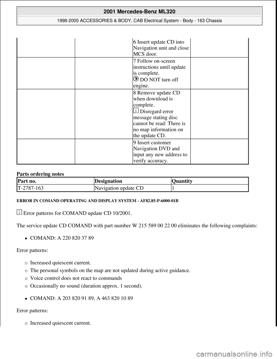
Parts ordering notes
ERROR IN COMAND OPERATING AND DISPLAY SYSTEM - AF82.85-P-6000-01B
Error patterns for COMAND update CD 10/2001.
The service update CD COMAND with part number W 215 589 00 22 00 eliminates the following complaints:
COMAND: A 220 820 37 89
Error patterns:
Increased quiescent current.
The personal symbols on the map are not updated during active guidance.
Voice control does not react to commands
Occasionally no sound (duration approx. 1 second).
COMAND: A 203 820 91 89, A 463 820 10 89
Error patterns:
Increased quiescent current.
6 Insert update CD into
Navigation unit and close
MCS door.
7 Follow on-screen
instructions until update
is complete.
DO NOT turn off
engine.
8 Remove update CD
when download is
complete.
Disregard error
message stating disc
cannot be read: There is
no map information on
the update CD.
9 Insert customer
Navigation DVD and
input any new address to
verify accuracy.
Part no.DesignationQuantity
T-2787-163Navigation update CD1
2001 Mercedes-Benz ML320
1998-2005 ACCESSORIES & BODY, CAB Electrical System - Body - 163 Chassis
me
Saturday, October 02, 2010 3:30:07 PMPage 180 © 2006 Mitchell Repair Information Company, LLC.