Page 2526 of 4133
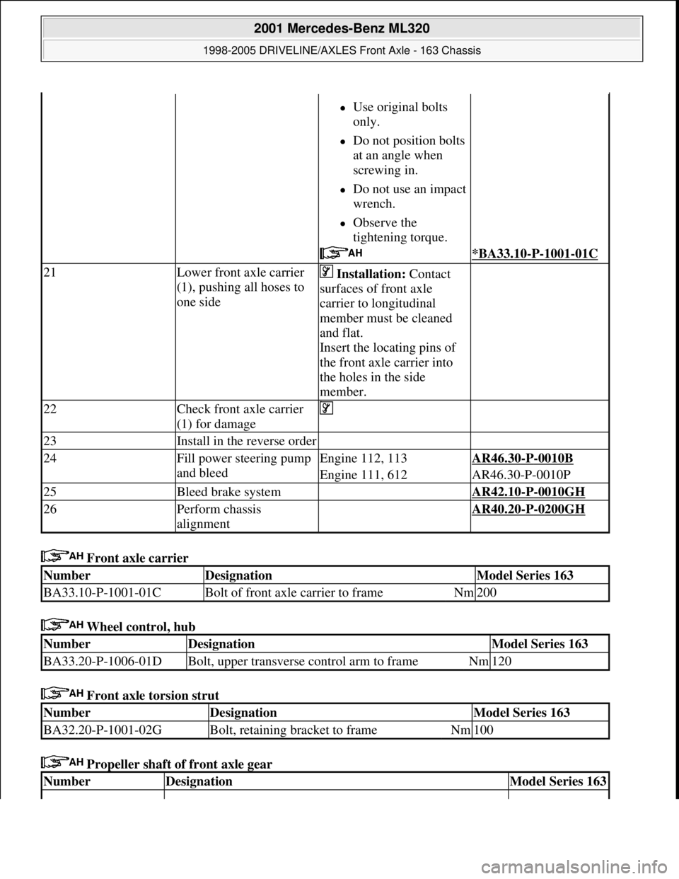
Front axle carrier
Wheel control, hub
Front axle torsion strut
Propeller shaft of front axle gear
Use original bolts
only.
Do not position bolts
at an angle when
screwing in.
Do not use an impact
wrench.
Observe the
tightening torque.
*BA33.10-P-1001-01C
21Lower front axle carrier
(1), pushing all hoses to
one side Installation: Contact
surfaces of front axle
carrier to longitudinal
member must be cleaned
and flat.
Insert the locating pins of
the front axle carrier into
the holes in the side
member.
22Check front axle carrier
(1) for damage
23Install in the reverse order
24Fill power steering pump
and bleedEngine 112, 113AR46.30-P-0010B
Engine 111, 612AR46.30-P-0010P
25Bleed brake system AR42.10-P-0010GH
26Perform chassis
alignment AR40.20-P-0200GH
NumberDesignationModel Series 163
BA33.10-P-1001-01CBolt of front axle carrier to frameNm200
NumberDesignationModel Series 163
BA33.20-P-1006-01DBolt, upper transverse control arm to frameNm120
NumberDesignationModel Series 163
BA32.20-P-1001-02GBolt, retaining bracket to frameNm100
NumberDesignationModel Series 163
2001 Mercedes-Benz ML320
1998-2005 DRIVELINE/AXLES Front Axle - 163 Chassis
me
Saturday, October 02, 2010 3:38:21 PMPage 7 © 2006 Mitchell Repair Information Company, LLC.
Page 2527 of 4133
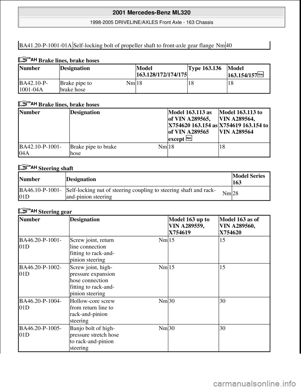
Brake lines, brake hoses
Brake lines, brake hoses
Steering shaft
Steering gear
BA41.20-P-1001-01ASelf-locking bolt of propeller shaft to front-axle gear flangeNm40
NumberDesignationModel
163.128/172/174/175Type 163.136Model
163.154/157
BA42.10-P-
1001-04ABrake pipe to
brake hoseNm181818
NumberDesignationModel 163.113 as
of VIN A289565,
X754620 163.154 as
of VIN A289565
except Model 163.113 to
VIN A289564,
X754619 163.154 to
VIN A289564
BA42.10-P-1001-
04ABrake pipe to brake
hoseNm1818
NumberDesignationModel Series
163
BA46.10-P-1001-
01DSelf-locking nut of steering coupling to steering shaft and rack-
and-pinion steeringNm28
NumberDesignationModel 163 up to
VIN A289559,
X754619Model 163 as of
VIN A289560,
X754620
BA46.20-P-1001-
01DScrew joint, return
line connection
fitting to rack-and-
pinion steeringNm1515
BA46.20-P-1002-
01DScrew joint, high-
pressure expansion
hose connection
fitting to rack-and-
pinion steeringNm1515
BA46.20-P-1004-
01DHollow-core screw
from return line to
rack-and-pinion
steeringNm3030
BA46.20-P-1005-
01DBanjo bolt of high-
pressure stretch hose
to rack-and-pinion
steeringNm3030
2001 Mercedes-Benz ML320
1998-2005 DRIVELINE/AXLES Front Axle - 163 Chassis
me
Saturday, October 02, 2010 3:38:21 PMPage 8 © 2006 Mitchell Repair Information Company, LLC.
Page 2532 of 4133
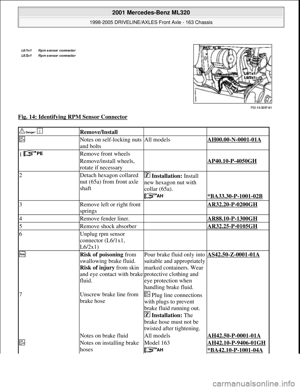
Fig. 14: Identifying RPM Sensor Connector
Remove/Install
Notes on self-locking nuts
and boltsAll modelsAH00.00-N-0001-01A
1 Remove front wheels
Remove/install wheels,
rotate if necessaryAP40.10-P-4050GH
2Detach hexagon collared
nut (65a) from front axle
shaft Installation: Install
new hexagon nut with
collar (65a).
*BA33.30-P-1001-02B
3Remove left or right front
springs AR32.20-P-0200GH
4Remove fender liner. AR88.10-P-1300GH
5Remove shock absorber AR32.25-P-0105GH
6Unplug rpm sensor
connector (L6/1x1,
L6/2x1)
Risk of poisoning from
swallowing brake fluid.
Risk of injury from skin
and eye contact with brake
fluid.Pour brake fluid only into
suitable and appropriately
marked containers. Wear
protective clothing and
eye protection when
handling brake fluid.AS42.50-Z-0001-01A
7Unscrew brake line from
brake hose Plug line connections
with plugs to prevent
brake fluid running out.
Installation: The
brake hose must not be
twisted after tightening.
Notes on brake fluidAll modelsAH42.50-P-0001-01A
Notes on installing brake
hosesModel 163AH42.10-P-9406-01GH
*BA42.10-P-1001-04A
2001 Mercedes-Benz ML320
1998-2005 DRIVELINE/AXLES Front Axle - 163 Chassis
me
Saturday, October 02, 2010 3:38:22 PMPage 13 © 2006 Mitchell Repair Information Company, LLC.
Page 2534 of 4133
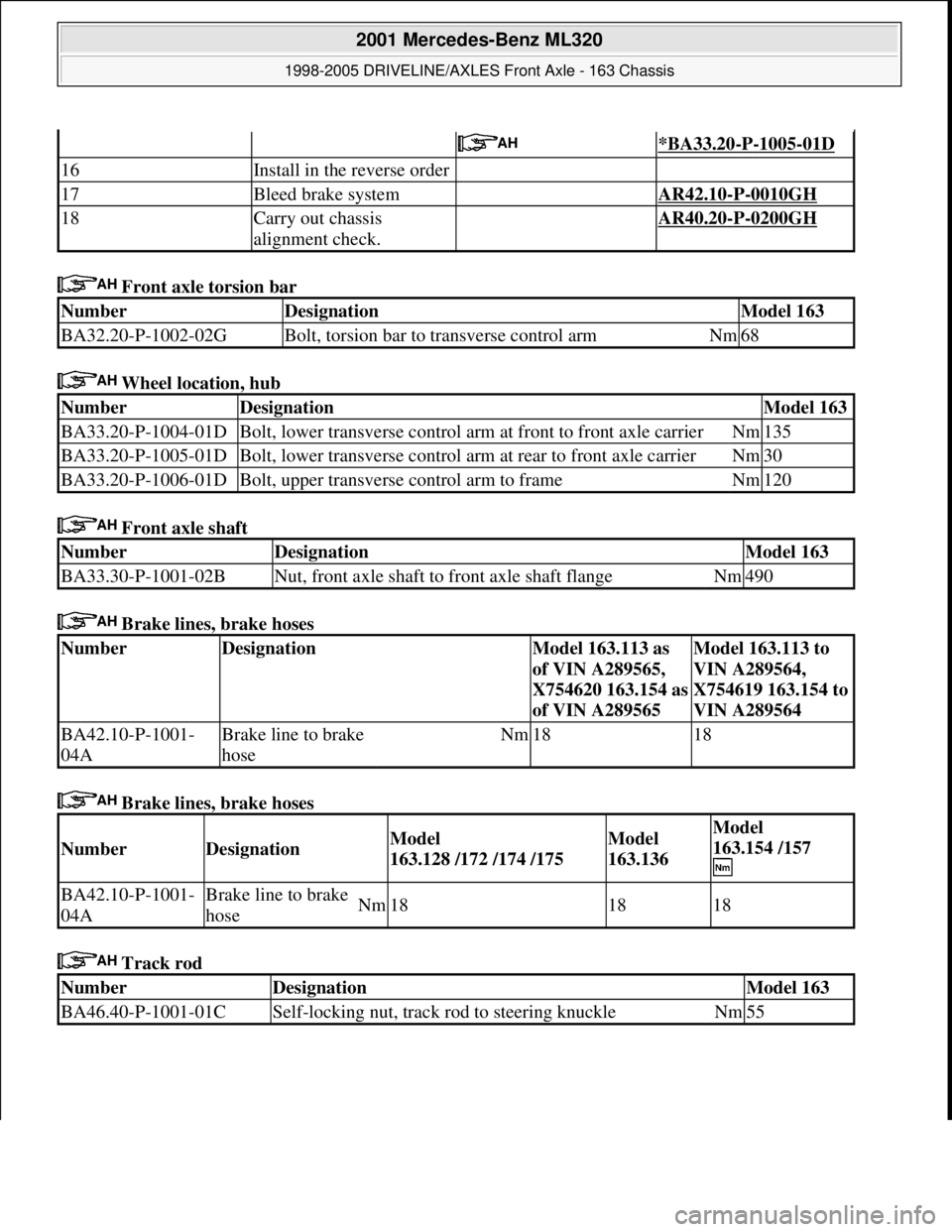
Front axle torsion bar
Wheel location, hub
Front axle shaft
Brake lines, brake hoses
Brake lines, brake hoses
Track rod
*BA33.20-P-1005-01D
16Install in the reverse order
17Bleed brake system AR42.10-P-0010GH
18Carry out chassis
alignment check. AR40.20-P-0200GH
NumberDesignationModel 163
BA32.20-P-1002-02GBolt, torsion bar to transverse control armNm68
NumberDesignationModel 163
BA33.20-P-1004-01DBolt, lower transverse control arm at front to front axle carrierNm135
BA33.20-P-1005-01DBolt, lower transverse control arm at rear to front axle carrierNm30
BA33.20-P-1006-01DBolt, upper transverse control arm to frameNm120
NumberDesignationModel 163
BA33.30-P-1001-02BNut, front axle shaft to front axle shaft flangeNm490
NumberDesignationModel 163.113 as
of VIN A289565,
X754620 163.154 as
of VIN A289565Model 163.113 to
VIN A289564,
X754619 163.154 to
VIN A289564
BA42.10-P-1001-
04ABrake line to brake
hoseNm1818
NumberDesignationModel
163.128 /172 /174 /175Model
163.136Model
163.154 /157
BA42.10-P-1001-
04ABrake line to brake
hoseNm181818
NumberDesignationModel 163
BA46.40-P-1001-01CSelf-locking nut, track rod to steering knuckleNm55
2001 Mercedes-Benz ML320
1998-2005 DRIVELINE/AXLES Front Axle - 163 Chassis
me
Saturday, October 02, 2010 3:38:22 PMPage 15 © 2006 Mitchell Repair Information Company, LLC.
Page 2547 of 4133
Fig. 43: Identifying Brake Caliper Dust Shield And Supporting Joint
Wheel location, hub
Remove
1Remove steering knuckle AR33.25-P-
0400GH
2Detach and rotate brake caliper dust shield
3Press supporting joint (7) out of steering knuckle (5) AR33.20-P-0440-
01GH
Install
4Pull in supporting joint (7) with locking slotted
round nut until it abuts
Replace locking
slotted nut.AR33.20-P-0440-
01GH
*BA33.20-P-1003-
01D
Claw-type wrenchFig. 38
5Attach brake caliper dust shield
6Install steering knuckle AR33.25-P-
0400GH
NumberDesignationModel Series 163
BA33.20-P-1003-01DLocking slotted nut, supporting joint to steering knuckleNM300
2001 Mercedes-Benz ML320
1998-2005 DRIVELINE/AXLES Front Axle - 163 Chassis
me
Saturday, October 02, 2010 3:38:22 PMPage 28 © 2006 Mitchell Repair Information Company, LLC.
Page 2550 of 4133
Fig. 49: Identifying Upper Wishbone Components
Remove/install
Notes on self-locking nuts and
boltsAll modelsAH00.00-N-
0001-01A
1
Remove front wheels
Remove, remount front road
wheels, rotate as necessaryAP40.10-P-
4050GH
2Remove shock absorber AR32.25-P-
0105GH
3Detach brake line bracket from
steering knuckle
4Use extractor to remove guide
joint from upper control arm (6)
AR33.20-P-
0500-01GH
*BA33.20-P-
1001-01D
Thrust pieceFig. 45
SupportFig. 46
PressFig. 47
5
Secure steering knuckle to shock
absorber with a wire to prevent it
from tilting down To avoid leaks within the hydraulic brake
system and open circuits in the electrical
wiring, never tug on the brake lines or the
electrical wiring.
2001 Mercedes-Benz ML320
1998-2005 DRIVELINE/AXLES Front Axle - 163 Chassis
me
Saturday, October 02, 2010 3:38:22 PMPage 31 © 2006 Mitchell Repair Information Company, LLC.
Page 2555 of 4133
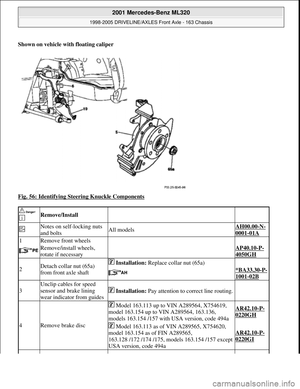
Shown on vehicle with floating caliper
Fig. 56: Identifying Steering Knuckle Components
Remove/Install
Notes on self-locking nuts
and boltsAll modelsAH00.00-N-
0001-01A
1Remove front wheels
Remove/install wheels,
rotate if necessaryAP40.10-P-
4050GH
2Detach collar nut (65a)
from front axle shaft Installation: Replace collar nut (65a)
*BA33.30-P-
1001-02B
3
Unclip cables for speed
sensor and brake lining
wear indicator from guides
Installation: Pay attention to correct line routing.
4Remove brake disc
Model 163.113 up to VIN A289564, X754619,
model 163.154 up to VIN A289564, 163.136,
models 163.154 /157 with USA version, code 494aAR42.10-P-
0220GH
Model 163.113 as of VIN A289565, X754620,
model 163.154 as of FIN A289565,
163.128 /172 /174 /175, models 163.154 /157 except
USA version, code 494a
AR42.10-P-
0220GI
2001 Mercedes-Benz ML320
1998-2005 DRIVELINE/AXLES Front Axle - 163 Chassis
me
Saturday, October 02, 2010 3:38:22 PMPage 36 © 2006 Mitchell Repair Information Company, LLC.
Page 2571 of 4133
Wheel location, hub
Remove/install wheels,
rotate if necessary AP40.10-P-
4050GH
2
Detach hexagon collared
nut (65a) from front axle
shaft Replace hexagon nut with collar
*BA33.30-P-
1001-02B
3Remove front axle brake
caliper
Hang the floating / fixed caliper to one side with a
hook to relieve the strain on the brake hose.
Leave brake hose connected.
Model 163.136, model 163.113 up to VIN A289564,
X754619, model 163.154 up to VIN A289564, model
163.154 /157 only with US version, code 494a.AR42.10-P-
0070GH
Model 163.128 /172 /174 /175, model 163.113 as of
VIN A289565, X754620, model 163.154 as of VIN
A289565, model 163.154 /157 except US version,
code 494a.
AR42.10-P-
0070GI
4Detach track rod from
steering knuckle
Check rubber boot and ball joint for wear and
damage.AR46.40-P-
0200-02C
*BA46.40-P-
1001-01C
Thrust pieceFig. 16
PullerFig. 17
5
Press follower joint out of
upper transverse control
arm using puller
Check rubber boot and ball joint for wear and damageAR33.20-P-
0500-01GH
*BA33.20-P-
1001-01D
Thrust pieceFig. 45
SupportFig. 46
PressFig. 47
6
Press front axle shaft (65)
out of front axle shaft
flange Hang steering knuckle to one side using wire.AR33.30-P-
0620-04GH
Extraction and installation toolFig. 18
7Lever front axle shaft out
of front axle gear Do not damage shield.
8Remove front axle shaft
(65) Installation: Make sure that the opening in the
circlip (65c) faces downward before inserting into the
front axle gear.
9Install in the reverse order
NumberDesignationModel
163
BA33.20-P-1001-
01DSelf-locking nut, upper transverse control arm follower joint to
steering knuckleNm50
2001 Mercedes-Benz ML320
1998-2005 DRIVELINE/AXLES Front Axle - 163 Chassis
me
Saturday, October 02, 2010 3:38:22 PMPage 52 © 2006 Mitchell Repair Information Company, LLC.