1997 MERCEDES-BENZ ML320 brake
[x] Cancel search: brakePage 1471 of 4133
Basically automatic transmission 722.6 with electronic control offers the following advantages:
Reduced Fuel Consumption
Improved Shift Comfort
More Favorable Gear Steps As A Result Of 5 Gears
Enhanced Life And Reliability
Reduced Servicing Costs
The electrohydraulic control unit is bolted onto the bottom of the transmission housing. The end of the
transmission is formed by an oil pan made of sheet steel.
The oil pressure for the converter lockup clutch and center multiple-disc clutch is supplied via holes in the input
shaft. The oil pressure to the rear multiple-disc clutch is routed through the output shaft. The lubricating oil is
supplied and distributed by additional bore holes in both shafts. All bearing points of the gear sets as well as
freewheels and shift elements are supplied with lubricating oil.
The parking lock gear and drive flange are connected to the output shaft by gearing.
Freewheels F1 and F2 optimize shifting. The front freewheel (F1) rests against the stator shaft extension on the
transmission side and connects the sun gear of the front planetary gear set to the transmission housing in the
locking direction.
The torque converter housing and transmission housing are made of a metal alloy. They are bolted together and
centered via the outer multiple-disc carrier of the multiple-disc brake B1. A coated intermediate panel seals the
two components.
The oil pump and outer multiple-disc carrier of the front multiple-disc brake are bolted to the converter housing.
The mechanical part consists of the propeller shaft, output shaft, a sun gear shaft and three planetary gearsets
which are coupled together.
In transmissions for powerful engines, the planetary gearsets have 4 planetary gears, while for less powerful
engines the front and rear planetary gear system has three planetary gear wheels. The stator shaft is pressed into
this and is secured against turning by a spline.
The rear freewheel F2 connects the sun gear of the center planetary gear set to the sun gear of the rear planetary
gearset in the locking direction.
The electrohydraulic control unit consists of the shift plate made of light alloy for hydraulic control and an
electronic control unit.
The electrical control unit consists of a supporting body made of plastic in which the electrical components are
combined. The shell is screwed to the shift plate. Conductor tracks which are integrated into the shell, connect
the electric components to a plug connector. This 13-pin plug connector forms the connection with the vehicle-
side wiring harness and with the ETC 5 (electronic transmission control) control module (N15/5) via a bayonet
lock.
2001 Mercedes-Benz ML320
1998-03 AUTOMATIC TRANSMISSIONS Complete Transmissions - ML 320 - 722.662
me
Saturday, October 02, 2010 3:15:30 PMPage 302 © 2006 Mitchell Repair Information Company, LLC.
Page 1489 of 4133
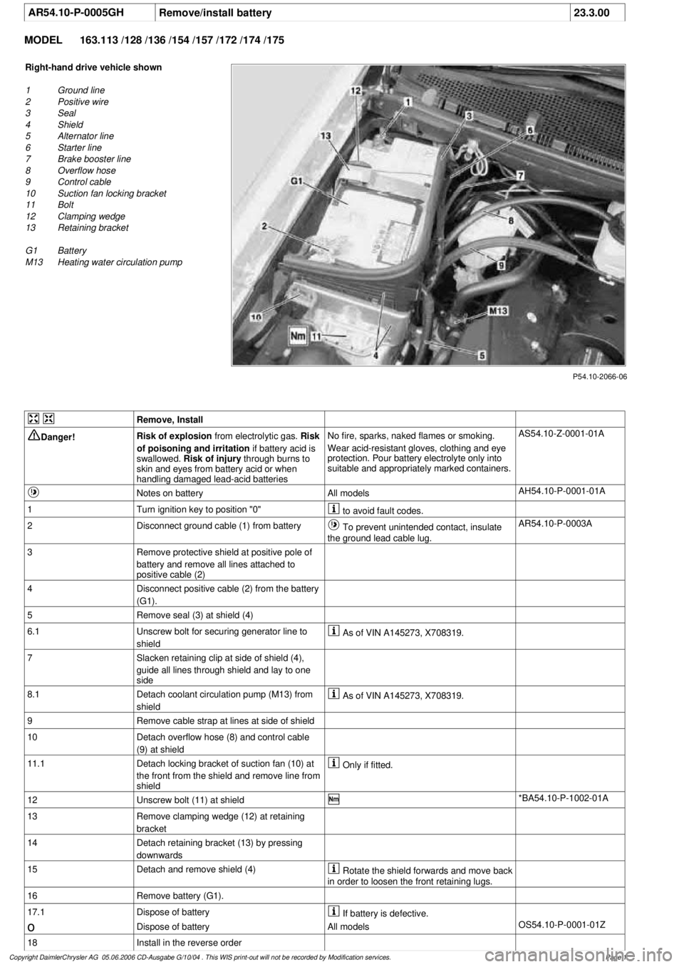
AR54.10-P-0005GH
Remove/install battery
23.3.00
MODEL
163.113 /128 /136 /154 /157 /172 /174 /175
P54.10-2066-06
Right-hand drive vehicle shown
1
Ground line
2
Positive wire
3
Seal
4
Shield
5
Alternator line
6
Starter line
7
Brake booster line
8
Overflow hose
9
Control cable
10
Suction fan locking bracket
11
Bolt
12
Clamping wedge
13
Retaining bracket
G1 Battery
M13
Heating water circulation pump
Remove, Install
Danger!
Risk of explosion
from electrolytic gas.
Risk
of poisoning and irritation
if battery acid is
swallowed.
Risk of injury
through burns to
skin and eyes from battery acid or when
handling damaged lead-acid batteries
No fire, sparks, naked flames or smoking.
Wear acid-resistant gloves, clothing and eye
protection. Pour battery electrolyte only into
suitable and appropriately marked containers.
AS54.10-Z-0001-01A
Notes on battery
All models
AH54.10-P-0001-01A
1
Turn ignition key to position "0"
to avoid fault codes.
2
Disconnect ground cable (1) from battery
To prevent unintended contact, insulate
the ground lead cable lug.
AR54.10-P-0003A
3
Remove protective shield at positive pole of
battery and remove all lines attached to
positive cable (2)
4
Disconnect positive cable (2) from the battery
(G1).
5
Remove seal (3) at shield (4)
6.1
Unscrew bolt for securing generator line to
shield
As of VIN A145273, X708319.
7
Slacken retaining clip at side of shield (4),
guide all lines through shield and lay to one
side
8.1
Detach coolant circulation pump (M13) from
shield
As of VIN A145273, X708319.
9
Remove cable strap at lines at side of shield
10
Detach overflow hose (8) and control cable
(9) at shield
11.1
Detach locking bracket of suction fan (10) at
the front from the shield and remove line from
shield
Only if fitted.
12
Unscrew bolt (11) at shield
*BA54.10-P-1002-01A
13
Remove clamping wedge (12) at retaining
bracket
14
Detach retaining bracket (13) by pressing
downwards
15
Detach and remove shield (4)
Rotate the shield forwards and move back
in order to loosen the front retaining lugs.
16
Remove battery (G1).
17.1
Dispose of battery
If battery is defective.
o
Dispose of battery
All models
OS54.10-P-0001-01Z
18
Install in the reverse order
Copyright DaimlerChrysler AG 05.06.2006 CD-Ausgabe G/10/04 . This WIS print-out will not be recorde
d by Modification services.
Page 1
Page 1540 of 4133
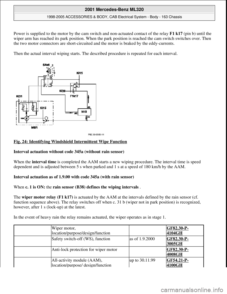
Power is supplied to the motor by the cam switch and non-actuated contact of the relay F1 k17(pin b) until the
wiper arm has reached its park position. When the park position is reached the cam switch switches over. Then
the two motor connectors are short-circuited and the motor is braked by the eddy-currents.
Then the actual interval wiping starts. The described procedure is repeated for each interval.
Fig. 24: Identifying Windshield Intermittent Wipe Function
Interval actuation without code 345a (without rain sensor)
When the interval time is completed the AAM starts a new wiping procedure. The interval time is speed
dependent and is adjusted between 5 s when parked and 1 s at a speed of 180 km/h by the AAM.
Interval actuation as of 1.9.00 with code 345a (with rain sensor)
When c. 1 is ON: the rain sensor (B38) defines the wiping intervals .
The wiper motor relay (F1 k17) is actuated by the AAM at the intervals defined by the rain sensor (cf.
function sequence above). The relay switches off when c. 31 b (wiper not in park position) is recognized,
however, after 1 s (lock-up) at the latest.
In the event of heavy rain the relay remains actuated, the wiper operates as in stage 1.
Wiper motor,
location/purpose/design/function GF82.30-P-
4104GH
Safety switch-off (WS), functionas of 1.9.2000GF82.30-P-
3005GH
Anti-lock protection for wiper motor GF82.30-P-
4008GH
All-activity module (AAM),
location/purpose/ design/functionup to 30.11.99GF54.21-P-
4100GH
2001 Mercedes-Benz ML320
1998-2005 ACCESSORIES & BODY, CAB Electrical System - Body - 163 Chassis
me
Saturday, October 02, 2010 3:30:04 PMPage 45 © 2006 Mitchell Repair Information Company, LLC.
Page 1541 of 4133
WIPER, FUNCTION - GF82.30-P-3004GH
MODEL 163
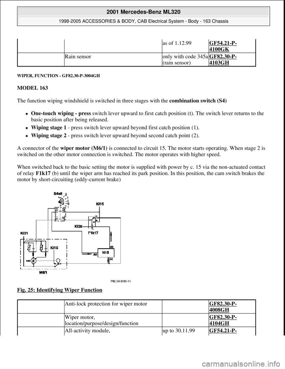
The function wiping windshield is switched in three stages with the combination switch (S4)
One-touch wiping - press switch lever upward to first catch position (t). The switch lever returns to the
basic position after being released.
Wiping stage 1 - press switch lever upward beyond first catch position (1).
Wiping stage 2 - press switch lever upward beyond second catch point (2).
A connector of the wiper motor (M6/1) is connected to circuit 15. The motor starts operating. When stage 2 is
switched on the other motor connection is switched. The motor operates with higher speed.
When switched back to the basic setting the motor is supplied with power by c. 15 via the non-actuated contact
of relay F1k17 (b) until the wiper arm has reached its park position. In this position, the cam switch brakes the
motor by short-circuiting (eddy-current brake)
Fig. 25: Identifying Wiper Function
as of 1.12.99GF54.21-P-
4100GK
Rain sensoronly with code 345a
(rain sensor)GF82.30-P-
4103GH
Anti-lock protection for wiper motor GF82.30-P-
4008GH
Wiper motor,
location/purpose/design/function GF82.30-P-
4104GH
All-activity module, up to 30.11.99GF54.21-P-
2001 Mercedes-Benz ML320
1998-2005 ACCESSORIES & BODY, CAB Electrical System - Body - 163 Chassis
me
Saturday, October 02, 2010 3:30:04 PMPage 46 © 2006 Mitchell Repair Information Company, LLC.
Page 1819 of 4133
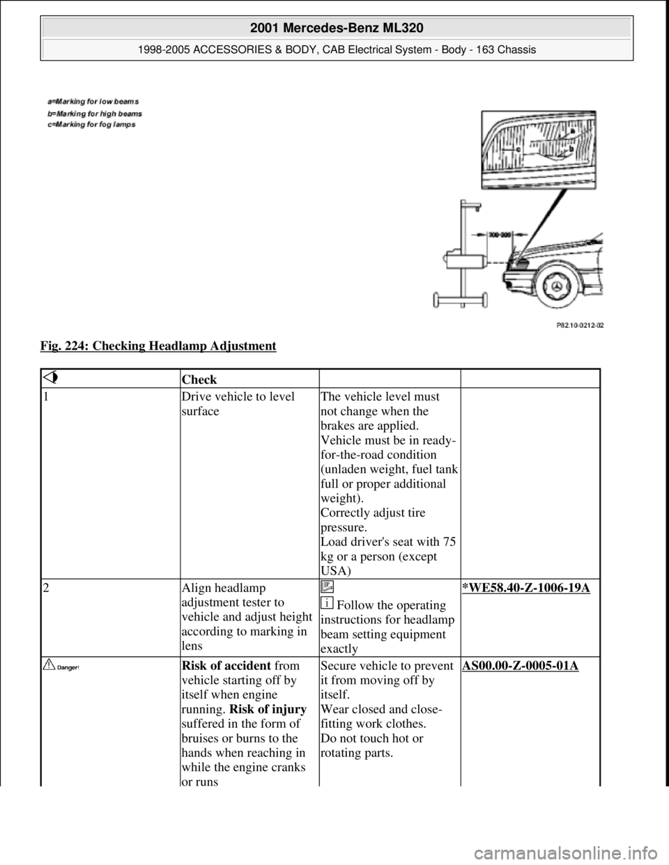
Fig. 224: Checking Headlamp Adjustment
Check
1Drive vehicle to level
surfaceThe vehicle level must
not change when the
brakes are applied.
Vehicle must be in ready-
for-the-road condition
(unladen weight, fuel tank
full or proper additional
weight).
Correctly adjust tire
pressure.
Load driver's seat with 75
kg or a person (except
USA)
2Align headlamp
adjustment tester to
vehicle and adjust height
according to marking in
lens
Follow the operating
instructions for headlamp
beam setting equipment
exactly*WE58.40-Z-1006-19A
Risk of accident from
vehicle starting off by
itself when engine
running. Risk of injury
suffered in the form of
bruises or burns to the
hands when reaching in
while the engine cranks
or runsSecure vehicle to prevent
it from moving off by
itself.
Wear closed and close-
fitting work clothes.
Do not touch hot or
rotating parts.AS00.00-Z-0005-01A
2001 Mercedes-Benz ML320
1998-2005 ACCESSORIES & BODY, CAB Electrical System - Body - 163 Chassis
me
Saturday, October 02, 2010 3:30:10 PMPage 324 © 2006 Mitchell Repair Information Company, LLC.
Page 1970 of 4133
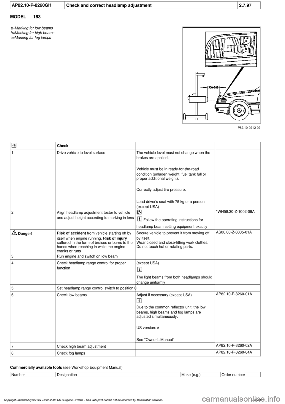
AP82.10-P-8260GH
Check and correct headlamp adjustment
2.7.97
MODEL
163
a=Marking for low beams
b=Marking for high beams
c=Marking for fog lamps
P82.10-0212-02
Check
1
Drive vehicle to level surface
The vehicle level must not change when the
brakes are applied.
Vehicle must be in ready-for-the-road
condition (unladen weight, fuel tank full or
proper additional weight).
Correctly adjust tire pressure.
Load driver's seat with 75 kg or a person
(except USA)
2
Align headlamp adjustment tester to vehicle
and adjust height according to marking in lens
Follow the operating instructions for
headlamp beam setting equipment exactly
*WH58.30-Z-1002-09A
Danger!
Risk of accident
from vehicle starting off by
itself when engine running.
Risk of injury
suffered in the form of bruises or burns to the
hands when reaching in while the engine
cranks or runs
Secure vehicle to prevent it from moving off
by itself.
Wear closed and close-fitting work clothes.
Do not touch hot or rotating parts.
AS00.00-Z-0005-01A
3
Run engine and switch on low beam
4
Check headlamp range control for proper
function
(except USA)
The light beams from both headlamps should
change uniformly
5
Set headlamp range control switch to position 0
6
Check low beams
Adjust if necessary (except USA)
AP82.10-P-8260-01A
Due to the common reflector unit, the low
beams, high beams and fog lamps are
adjusted simultaneously.
US version:
#
See "Owner's Manual"
7
Check high beam adjustment
AP82.10-P-8260-02A
8
Check fog lamps
AP82.10-P-8260-04A
Commercially available tools
(see Workshop Equipment Manual)
Number
Designation
Make (e.g.)
Order number
Copyright DaimlerChrysler AG 20.05.2006 CD-Ausgabe G/10/04 . This WIS print-out will not be recorde
d by Modification services.
Page 1
Page 1988 of 4133
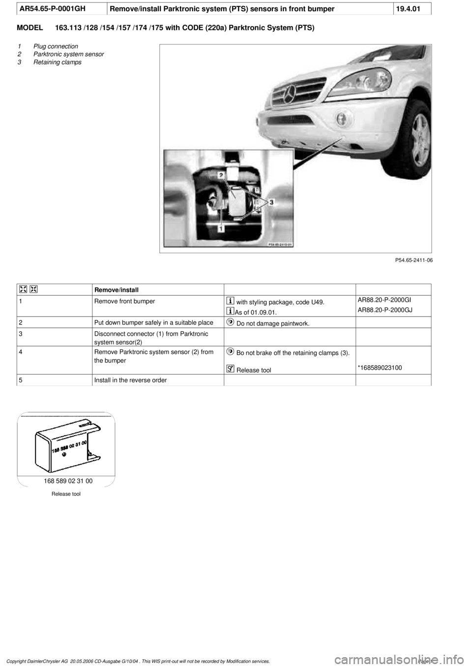
AR54.65-P-0001GH
Remove/install Parktronic system (PTS) sensors in front bumper
19.4.01
MODEL
163.113 /128 /154 /157 /174 /175 with CODE (220a) Parktronic System (PTS)
P54.65-2411-06
1
Plug connection
2
Parktronic system sensor
3
Retaining clamps
Remove/install
1
Remove front bumper
with styling package, code U49.
AR88.20-P-2000GI
As of 01.09.01.
AR88.20-P-2000GJ
2
Put down bumper safely in a suitable place
Do not damage paintwork.
3
Disconnect connector (1) from Parktronic
system sensor(2)
4
Remove Parktronic system sensor (2) from
the bumper
Bo not brake off the retaining clamps (3).
Release tool
*168589023100
5
Install in the reverse order
Release tool
168 589 02 31 00
Copyright DaimlerChrysler AG 20.05.2006 CD-Ausgabe G/10/04 . This WIS print-out will not be recorde
d by Modification services.
Page 1
Page 1991 of 4133
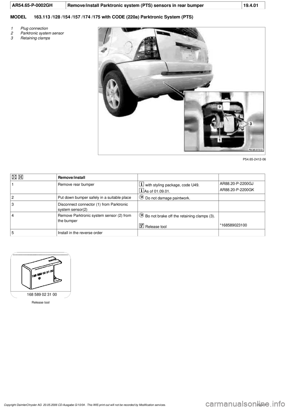
AR54.65-P-0002GH
Remove/install Parktronic system (PTS) sensors in rear bumper
19.4.01
MODEL
163.113 /128 /154 /157 /174 /175 with CODE (220a) Parktronic System (PTS)
P54.65-2412-06
1
Plug connection
2
Parktronic system sensor
3
Retaining clamps
Remove/install
1
Remove rear bumper
with styling package, code U49.
AR88.20-P-2200GJ
As of 01.09.01.
AR88.20-P-2200GK
2
Put down bumper safely in a suitable place
Do not damage paintwork.
3
Disconnect connector (1) from Parktronic
system sensor(2)
4
Remove Parktronic system sensor (2) from
the bumper
Bo not brake off the retaining clamps (3).
Release tool
*168589023100
5
Install in the reverse order
Release tool
168 589 02 31 00
Copyright DaimlerChrysler AG 20.05.2006 CD-Ausgabe G/10/04 . This WIS print-out will not be recorde
d by Modification services.
Page 1