Page 3961 of 4133

AD54.30-P-5000-02A
Display instruments controlled via CAN
troubleshooting chart IC
The following display instruments or indicator lamps/ malfunction
indicator lamps receive their information from the traction system
control module (N47) via CAN data buses (an appropriate message
appears in the display on vehicles with multi-function display):
D
Total mileage recorder, trip odometer
D
Electronic speedometer
D
Low brake fluid level/parking brake indicator lamp (except model 163
parking brake indicator lamp only via CAN)
D
Brake pad wear indicator lamp
D
ABS MIL
D
ETS, ASR, ESP indicator lamp
D
ETS, ASR, ESP malfunction indicator lamp
Model 163 only:
The
"Low-Range"
indicator lamp receives its information from the
transfer case control module (N78) via CAN data buses.
The
"Fog lamps"
indicator lamp (only model 163 except
I
) receives
its information from the All-activity module (AAM, N10) via CAN data
buses.
Model 168 only:
The
" Gear indicator "
indicator lamp receives its information from the
gear recognition module (A61) or from automatic clutch control module
(N15/4) via CAN data buses.
The following display instruments or indicator lamps/
malfunction indicator lamps receive their information from the
injection system control module (N3) via CAN data buses (an
appropriate message appears in the display on vehicles with
multi-function display):
D
Tachometer
D
Low engine oil level lamp
D
Engine coolant temperature
D
Preglow indicator lamp (diesel only)
D
Vehicle speed warning
D
Vehicle speed limit warning
D
Severe leak warning (
I
only), the fuel reserve indicator lamp
(A1e4) flashes
D
Active Service System (ASSYST):
D
Oil condition
D
Oil level
D
Oil temperature
D
Mass volumetric efficiency (load moment)
D
Engine speed, engine coolant temperature
Copyright DaimlerChrysler AG 05.06.2006 CD-Ausgabe G/10/04 . This WIS print-out will not be recorde
d by Modification services.
Page 1
Page 3988 of 4133
AD54.30-P-3000-02A
Warning buzzer function check IC
Warning buzzer
D
Light reminder and parking brake reminder
D
Key reminder
I
D
Seat belt reminder
for approx. 6 s
I
,
M
,
H
and Korea
for approx. 12 s
G
The warning tone is interrupted as soon as the seat belt buckle is
inserted.
D
Warning tone for a shortage of oil
D
Vehicle speed warning
G
> 120 km/h, v-limit warning (cruise
control)
D
In addition the symbol for vehicle speed warning appears in the
instrument cluster with multi-function display.
D
On model 163 a warning tone sounds for approx. 5 seconds if the
CAN signal is unusable.
D
Model 168 with automatic clutch system features an audible gear
warning.
It sounds if a gear is engaged at the same time as the driver's
door is opened. Brake and accelerator pedal must not be
operated.
Copyright DaimlerChrysler AG 05.06.2006 CD-Ausgabe G/10/04 . This WIS print-out will not be recorde
d by Modification services.
Page 1
Page 3994 of 4133

AP40.10-P-4050GH
Remove/install wheels, rotate if necessary
15.7.97
MODEL
163
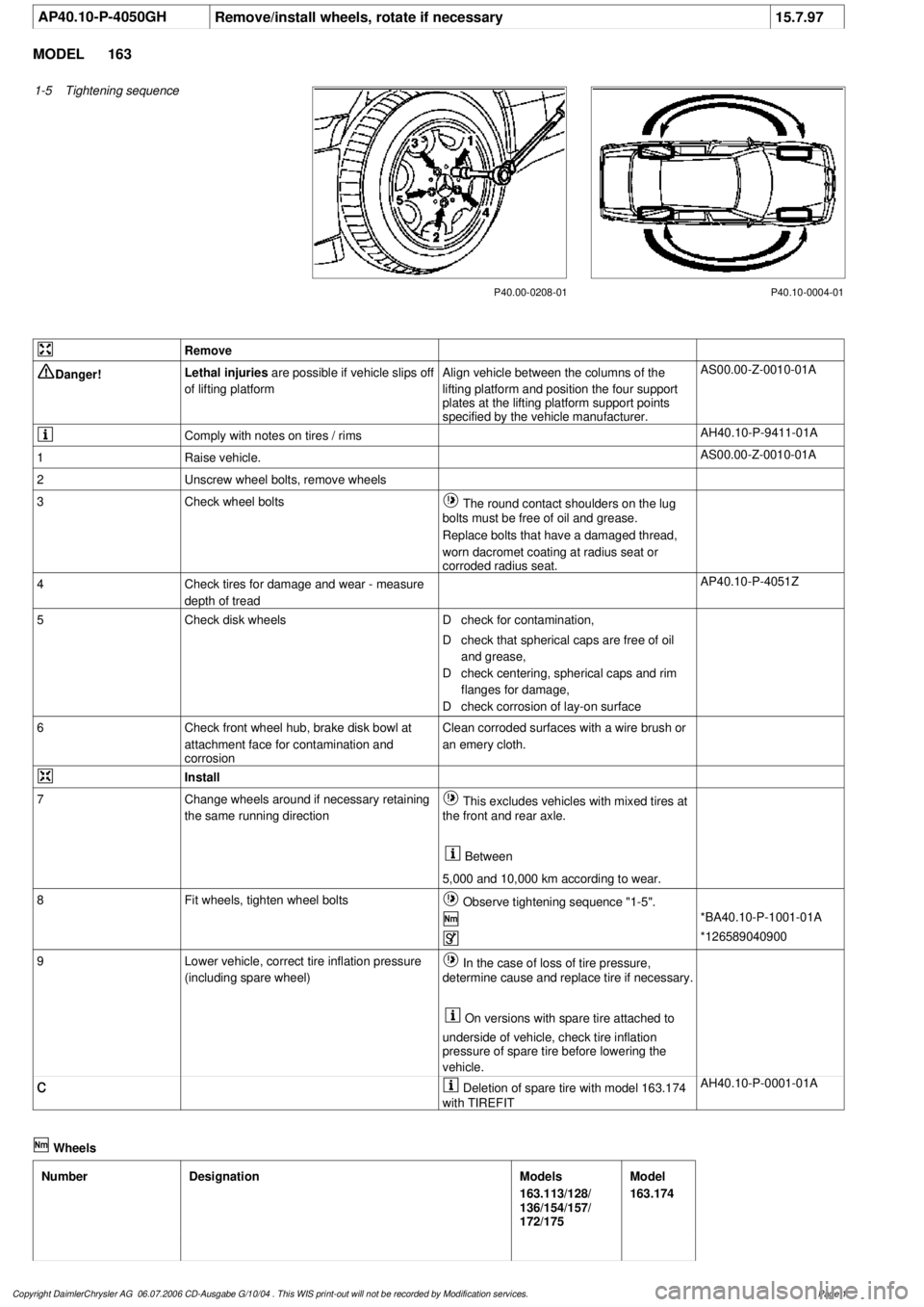
1-5
Tightening sequence
P40.10-0004-01
P40.00-0208-01
Remove
Danger!
Lethal injuries
are possible if vehicle slips off
of lifting platform
Align vehicle between the columns of the
lifting platform and position the four support
plates
at the lifting platform support points
specified by the vehicle manufacturer.
AS00.00-Z-0010-01A
Comply with notes on tires / rims
AH40.10-P-9411-01A
1
Raise vehicle.
AS00.00-Z-0010-01A
2
Unscrew wheel bolts, remove wheels
3
Check wheel bolts
The round contact shoulders on the lug
bolts must be free of oil and grease.
Replace bolts that have a damaged thread,
worn dacromet coating at radius seat or
corroded radius seat.
4
Check tires for damage and wear - measure
depth of tread
AP40.10-P-4051Z
5
Check disk wheels
D
check for contamination,
D
check that spherical caps are free of oil
and grease,
D
check centering, spherical caps and rim
flanges for damage,
D
check corrosion of lay-on surface
6
Check front wheel hub, brake disk bowl at
attachment face for contamination and
corrosion
Clean corroded surfaces with a wire brush or
an emery cloth.
Install
7
Change wheels around if necessary retaining
the same running direction
This excludes vehicles with mixed tires at
the front and rear axle.
Between
5,000 and 10,000 km according to wear.
8
Fit wheels, tighten wheel bolts
Observe tightening sequence "1-5".
*BA40.10-P-1001-01A
*126589040900
9
Lower vehicle, correct tire inflation pressure
(including spare wheel)
In the case of loss of tire pressure,
determine cause and replace tire if necessary.
On versions with spare tire attached to
underside of vehicle, check tire inflation
pressure of spare tire before lowering the
vehicle.
c
Deletion of spare tire with model 163.174
with TIREFIT
AH40.10-P-0001-01A
Wheels
Number
Designation
Models
163.113/128/
136/154/157/
172/175
Model
163.174
Copyright DaimlerChrysler AG 06.07.2006 CD-Ausgabe G/10/04 . This WIS print-out will not be recorde
d by Modification services.
Page 1
Page 4007 of 4133
Fig. 4: Manual A/C Circuit, W/O Coolant Fan Control Module (2 of 2)
ANTI-LOCK BRAKES
2001 Mercedes-Benz ML320
2001 SYSTEM WIRING DIAGRAMS Mercedes-Benz - ML320
me
Saturday, October 02, 2010 3:27:58 PMPage 9 © 2006 Mitchell Repair Information Company, LLC.
Page 4009 of 4133
Fig. 5: Anti-Lock Brakes Circuit (1 of 2)
2001 Mercedes-Benz ML320
2001 SYSTEM WIRING DIAGRAMS Mercedes-Benz - ML320
me
Saturday, October 02, 2010 3:27:58 PMPage 11 © 2006 Mitchell Repair Information Company, LLC.
Page 4011 of 4133
Fig. 6: Anti-Lock Brakes Circuit (2 of 2)
2001 Mercedes-Benz ML320
2001 SYSTEM WIRING DIAGRAMS Mercedes-Benz - ML320
me
Saturday, October 02, 2010 3:27:59 PMPage 13 © 2006 Mitchell Repair Information Company, LLC.
Page 4013 of 4133
Fig. 7: Brake Assist Circuit
ANTI-THEFT
2001 Mercedes-Benz ML320
2001 SYSTEM WIRING DIAGRAMS Mercedes-Benz - ML320
me
Saturday, October 02, 2010 3:27:59 PMPage 15 © 2006 Mitchell Repair Information Company, LLC.