1997 MERCEDES-BENZ ML320 brake
[x] Cancel search: brakePage 3049 of 4133
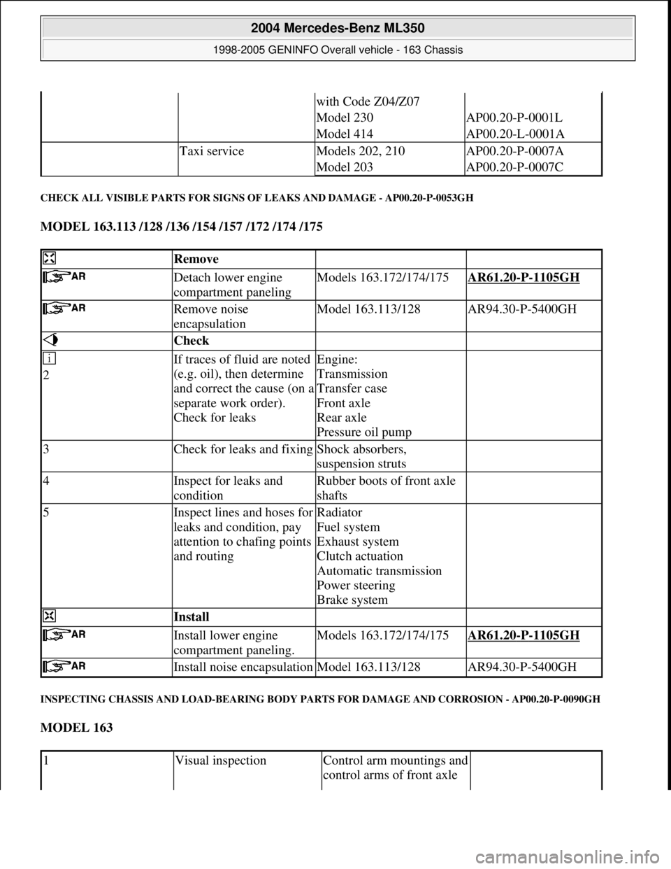
CHECK ALL VISIBLE PARTS FOR SIGNS OF LEAKS AND DAMAGE - AP00.20-P-0053GH
MODEL 163.113 /128 /136 /154 /157 /172 /174 /175
INSPECTING CHASSIS AND LOAD-BEARING BODY PARTS FOR DAMAGE AND CORROSION - AP00.20-P-0090GH
MODEL 163
with Code Z04/Z07
Model 230AP00.20-P-0001L
Model 414AP00.20-L-0001A
Taxi serviceModels 202, 210AP00.20-P-0007A
Model 203AP00.20-P-0007C
Remove
Detach lower engine
compartment panelingModels 163.172/174/175AR61.20-P-1105GH
Remove noise
encapsulationModel 163.113/128AR94.30-P-5400GH
Check
2If traces of fluid are noted
(e.g. oil), then determine
and correct the cause (on a
separate work order).
Check for leaksEngine:
Transmission
Transfer case
Front axle
Rear axle
Pressure oil pump
3Check for leaks and fixingShock absorbers,
suspension struts
4Inspect for leaks and
conditionRubber boots of front axle
shafts
5Inspect lines and hoses for
leaks and condition, pay
attention to chafing points
and routingRadiator
Fuel system
Exhaust system
Clutch actuation
Automatic transmission
Power steering
Brake system
Install
Install lower engine
compartment paneling.Models 163.172/174/175AR61.20-P-1105GH
Install noise encapsulationModel 163.113/128AR94.30-P-5400GH
1Visual inspectionControl arm mountings and
control arms of front axle
2004 Mercedes-Benz ML350
1998-2005 GENINFO Overall vehicle - 163 Chassis
me
Saturday, October 02, 2010 3:47:52 PMPage 404 © 2006 Mitchell Repair Information Company, LLC.
Page 3050 of 4133
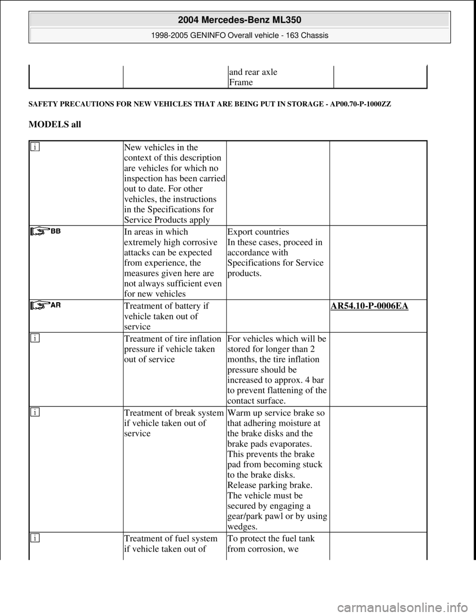
SAFETY PRECAUTIONS FOR NEW VEHICLES THAT ARE BEING PUT IN STORAGE - AP00.70-P-1000ZZ
MODELS all
and rear axle
Frame
New vehicles in the
context of this description
are vehicles for which no
inspection has been carried
out to date. For other
vehicles, the instructions
in the Specifications for
Service Products apply
In areas in which
extremely high corrosive
attacks can be expected
from experience, the
measures given here are
not always sufficient even
for new vehiclesExport countries
In these cases, proceed in
accordance with
Specifications for Service
products.
Treatment of battery if
vehicle taken out of
service AR54.10-P-0006EA
Treatment of tire inflation
pressure if vehicle taken
out of serviceFor vehicles which will be
stored for longer than 2
months, the tire inflation
pressure should be
increased to approx. 4 bar
to prevent flattening of the
contact surface.
Treatment of break system
if vehicle taken out of
serviceWarm up service brake so
that adhering moisture at
the brake disks and the
brake pads evaporates.
This prevents the brake
pad from becoming stuck
to the brake disks.
Release parking brake.
The vehicle must be
secured by engaging a
gear/park pawl or by using
wedges.
Treatment of fuel system
if vehicle taken out of To protect the fuel tank
from corrosion, we
2004 Mercedes-Benz ML350
1998-2005 GENINFO Overall vehicle - 163 Chassis
me
Saturday, October 02, 2010 3:47:52 PMPage 405 © 2006 Mitchell Repair Information Company, LLC.
Page 3052 of 4133
procedure or when
working near engine
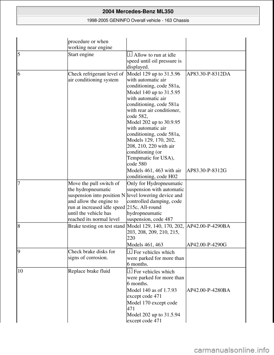
5Start engine Allow to run at idle
speed until oil pressure is
displayed.
6Check refrigerant level of
air conditioning systemModel 129 up to 31.5.96
with automatic air
conditioning, code 581a,AP83.30-P-8312DA
Model 140 up to 31.5.95
with automatic air
conditioning, code 581a
with rear air conditioner,
code 582,
Model 202 up to 30.9.95
with automatic air
conditioning, code 581a,
Models 129, 170, 202,
208, 210, 220 with air
conditioning (or
Tempmatic for USA),
code 580
Models 461, 463 with air
conditioning, code H02AP83.30-P-8312G
7Move the pull switch of
the hydropneumatic
suspension into position N
and allow the engine to
run at increased idle speed
until the vehicle has
reached its normal levelOnly for Hydropneumatic
suspension with automatic
level lowering device and
controlled damping, code
215c, All-round
hydropneumatic
suspension, code 487
8Brake testing on test standModel 129, 140, 170, 202,
203, 208, 209, 210, 215,
220AP42.00-P-4290BA
Models 461, 463AP42.00-P-4290G
9Check brake disks for
signs of corrosion. For vehicles which
were parked for more than
6 months.
10Replace brake fluid For vehicles which
were parked for more than
6 months.
Model 140 as of 1.7.93
except code 471AP42.00-P-4280BA
Model 170 except code
471
Model 202 up to 31.5.94
except code 471
2004 Mercedes-Benz ML350
1998-2005 GENINFO Overall vehicle - 163 Chassis
me
Saturday, October 02, 2010 3:47:52 PMPage 407 © 2006 Mitchell Repair Information Company, LLC.
Page 3175 of 4133
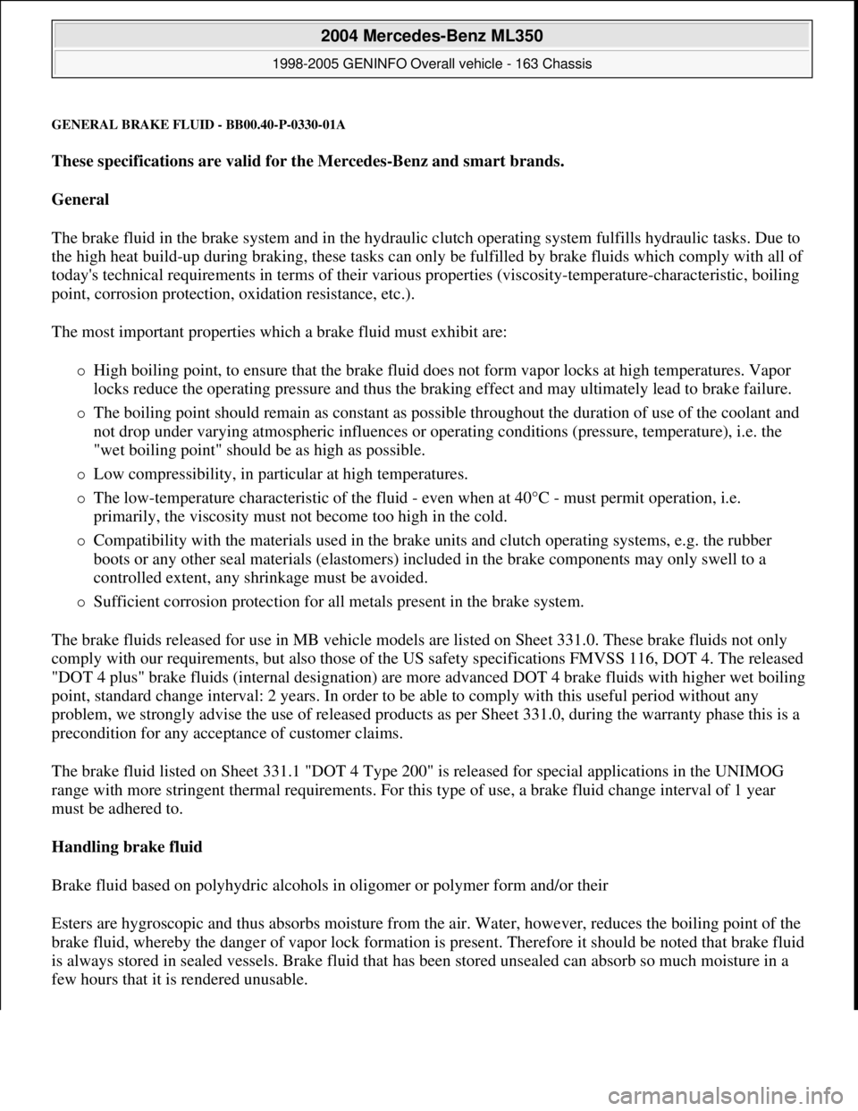
GENERAL BRAKE FLUID - BB00.40-P-0330-01A
These specifications are valid for the Mercedes-Benz and smart brands.
General
The brake fluid in the brake system and in the hydraulic clutch operating system fulfills hydraulic tasks. Due to
the high heat build-up during braking, these tasks can only be fulfilled by brake fluids which comply with all of
today's technical requirements in terms of their various properties (viscosity-temperature-characteristic, boiling
point, corrosion protection, oxidation resistance, etc.).
The most important properties which a brake fluid must exhibit are:
High boiling point, to ensure that the brake fluid does not form vapor locks at high temperatures. Vapor
locks reduce the operating pressure and thus the braking effect and may ultimately lead to brake failure.
The boiling point should remain as constant as possible throughout the duration of use of the coolant and
not drop under varying atmospheric influences or operating conditions (pressure, temperature), i.e. the
"wet boiling point" should be as high as possible.
Low compressibility, in particular at high temperatures.
The low-temperature characteristic of the fluid - even when at 40°C - must permit operation, i.e.
primarily, the viscosity must not become too high in the cold.
Compatibility with the materials used in the brake units and clutch operating systems, e.g. the rubber
boots or any other seal materials (elastomers) included in the brake components may only swell to a
controlled extent, any shrinkage must be avoided.
Sufficient corrosion protection for all metals present in the brake system.
The brake fluids released for use in MB vehicle models are listed on Sheet 331.0. These brake fluids not only
comply with our requirements, but also those of the US safety specifications FMVSS 116, DOT 4. The released
"DOT 4 plus" brake fluids (internal designation) are more advanced DOT 4 brake fluids with higher wet boiling
point, standard change interval: 2 years. In order to be able to comply with this useful period without any
problem, we strongly advise the use of released products as per Sheet 331.0, during the warranty phase this is a
precondition for any acceptance of customer claims.
The brake fluid listed on Sheet 331.1 "DOT 4 Type 200" is released for special applications in the UNIMOG
range with more stringent thermal requirements. For this type of use, a brake fluid change interval of 1 year
must be adhered to.
Handling brake fluid
Brake fluid based on polyhydric alcohols in oligomer or polymer form and/or their
Esters are hygroscopic and thus absorbs moisture from the air. Water, however, reduces the boiling point of the
brake fluid, whereby the danger of vapor lock formation is present. Therefore it should be noted that brake fluid
is always stored in sealed vessels. Brake fluid that has been stored unsealed can absorb so much moisture in a
few hours that it is rendered unusable.
2004 Mercedes-Benz ML350
1998-2005 GENINFO Overall vehicle - 163 Chassis
me
Saturday, October 02, 2010 3:47:57 PMPage 530 © 2006 Mitchell Repair Information Company, LLC.
Page 3176 of 4133
Because the brake fluid also absorbs moisture through the vent bore on the expansion reservoir, the wheel brake
cylinder and the brake hoses, the brake fluid has to be changed for safety reasons at regular intervals, best done
in the spring. When performing this change, make sure that the old fluid is also drained off the clutch system.
Generally, it is vital for the brake/clutch system to be completely drained before being filled with new fluid!
For the above-mentioned reasons, used brake fluid must not be used again.
The brake fluid is amber in color and thus can be easily confused with mineral products.
Therefore, brake fluids should always only be taken from original containers and stored separately from other
mineral oils and fluids.
When performing maintenance operations and repairs on brake parts, make sure that fuel, mineral oil, grease or
suchlike do not enter the brake system. Hydrocarbon-based materials will lead to swelling of the elastomers in
the brake and clutch system and - even in low concentrations - will suffice to cause total failure of the systems.
Only new brake fluid may be used as a rinsing and cleaning agent for the cylinders, lines and the expansion
reservoir of the hydraulic brake system.
Experience shows that before handling brake fluid, the hands must be cleaned and any oil and grease removed.
Brake fluid acts aggressively towards paint and color. In the event of any brake fluid spills or splashes, it must
be rinsed away immediately using copious amounts of water (do not rub it away).
Brake fluid disposal
When disposing of brake fluid, the relevant national specifications must be observed. It is advisable to try to
have the brake fluid disposed of as economic good; this is contingent on
Strict separation of used brake fluid from other materials;
Presence of a disposal channel, which justifies its classification as an economic good, i.e. a proper
alternate usage must be assured.
If this procedure is not possible, used brake fluid is to be disposed of together with any, e.g. paint residue,
solvents and suchlike. Any adding of used oil must be avoided, as it will result in difficulties, if the used oil is to
be recycled; in several countries this is prohibited by the legislators.
MISCELLANEOUS NOTES
NOTES ON SCRAPPING GAS-FILLED HYDRAULIC COMPONENTS - OS00.00-P-1000-01A
all
Unusable gas pressure dampers, spring accumulators, pressure reservoirs and impact absorbers have to be
depressurized before being scrapped according to the respective valid accident prevention regulations. These
safety measures are necessary because gas pressurized hydraulic parts can explode if heat is applied. A risk of
explosion is
given, e.g. when scrapping with cutting torches, smelting or if gas pressurized parts in landfills start
2004 Mercedes-Benz ML350
1998-2005 GENINFO Overall vehicle - 163 Chassis
me
Saturday, October 02, 2010 3:47:57 PMPage 531 © 2006 Mitchell Repair Information Company, LLC.
Page 3186 of 4133
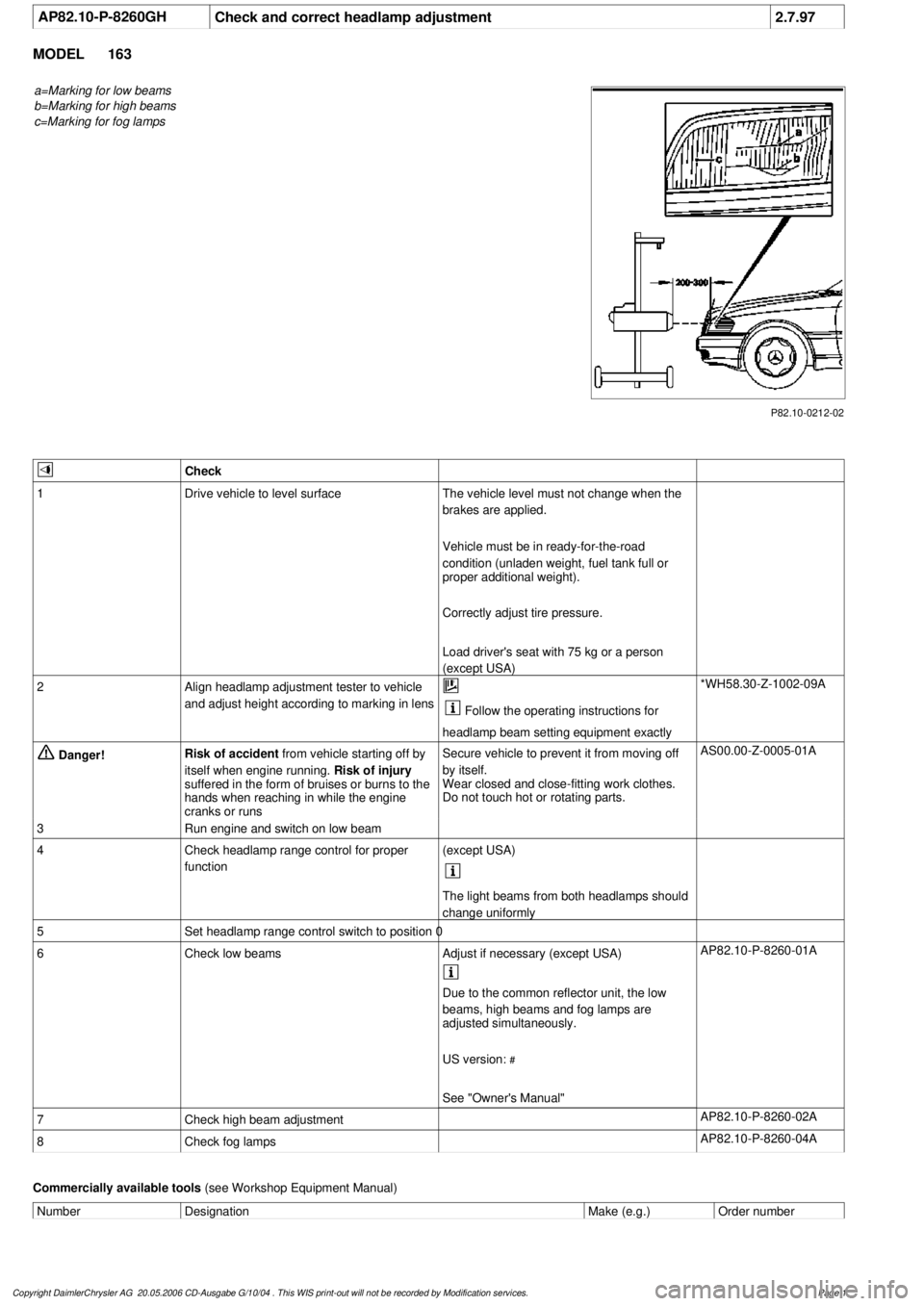
AP82.10-P-8260GH
Check and correct headlamp adjustment
2.7.97
MODEL
163
a=Marking for low beams
b=Marking for high beams
c=Marking for fog lamps
P82.10-0212-02
Check
1
Drive vehicle to level surface
The vehicle level must not change when the
brakes are applied.
Vehicle must be in ready-for-the-road
condition (unladen weight, fuel tank full or
proper additional weight).
Correctly adjust tire pressure.
Load driver's seat with 75 kg or a person
(except USA)
2
Align headlamp adjustment tester to vehicle
and adjust height according to marking in lens
Follow the operating instructions for
headlamp beam setting equipment exactly
*WH58.30-Z-1002-09A
Danger!
Risk of accident
from vehicle starting off by
itself when engine running.
Risk of injury
suffered in the form of bruises or burns to the
hands when reaching in while the engine
cranks or runs
Secure vehicle to prevent it from moving off
by itself.
Wear closed and close-fitting work clothes.
Do not touch hot or rotating parts.
AS00.00-Z-0005-01A
3
Run engine and switch on low beam
4
Check headlamp range control for proper
function
(except USA)
The light beams from both headlamps should
change uniformly
5
Set headlamp range control switch to position 0
6
Check low beams
Adjust if necessary (except USA)
AP82.10-P-8260-01A
Due to the common reflector unit, the low
beams, high beams and fog lamps are
adjusted simultaneously.
US version:
#
See "Owner's Manual"
7
Check high beam adjustment
AP82.10-P-8260-02A
8
Check fog lamps
AP82.10-P-8260-04A
Commercially available tools
(see Workshop Equipment Manual)
Number
Designation
Make (e.g.)
Order number
Copyright DaimlerChrysler AG 20.05.2006 CD-Ausgabe G/10/04 . This WIS print-out will not be recorde
d by Modification services.
Page 1
Page 3220 of 4133
FUNCTIONAL TEST PREPARATION
1. Check condition of fuses F16, F41, F43 and F44. See WIRING DIAGRAMS . Repair and/or replace
fuses and necessary.
2. Turn ignition on. Locate in-vehicle temperature sensor aspirator blower vent grille above anti-theft
indicator light. Place a half-inch square of tissue paper over aspirator blower vent grille. If paper stays on
vent grille, go to next step. If paper does not stay on vent grille, correct insufficient aspirator blower
ventilation.
3. Put shift lever in "P" and engage parking brake. Run engine at idle until it reaches normal operating
temperature, about 176°F (80°C). Ensure ambient (outside) temperature is greater than 58°F (15°C).
4. Manually open center and side air outlets. Ensure recirculation button is not depressed. Set blower speed
knob to position No. 1.
FUNCTION TEST
Defrost Mode
To check operation in defrost mode, set temperature selector knob to White range (vertical). Set mode control
knob to 12-o'clock position (vertical). Ensure A/C button indicator is illuminated. Air will vent from defrost and
center outlets and A/C compressor will engage. If operation is not as specified, perform the following in order:
Check voltage supply circuit Z50/2 between No. 16 fuse (15-amp) and connected components. See
VOLTAGE SUPPLY CIRCUIT Z50/2
under ELECTRICAL TESTS.
Check ground circuit. See GROUND CIRCUIT Z50/4 under ELECTRICAL TESTS.
Check in-vehicle temperature sensor signal voltage. See IN-VEHICLE TEMPERATURE SENSOR
under ELECTRICAL TESTS.
Check in-vehicle temperature sensor signal resistance. See IN-VEHICLE TEMPERATURE SENSOR
under ELECTRICAL TESTS.
Check icing protection temperature sensor signal voltage. See ICING PROTECTION
TEMPERATURE SENSOR under ELECTRICAL TESTS.
Check icing protection temperature sensor resistance. See ICING PROTECTION TEMPERATURE
SENSOR under ELECTRICAL TESTS.
Check activation voltage during temperature reduction. See ACTIVATION VOLTAGE
TEMPERATURE under ELECTRICAL TESTS.
Check activation voltage during temperature increase. See ACTIVATION VOLTAGE
TEMPERATURE under ELECTRICAL TESTS.
Check blend air flap actuator motor operation voltage. See BLEND AIR FLAP ACTUATOR MOTOR
under ELECTRICAL TESTS.
Check blend air flap actuator motor resistance. See BLEND AIR FLAP ACTUATOR MOTOR under
ELECTRICAL TESTS.
Check A/C button activation. See A/C BUTTON under ELECTRICAL TESTS.
Check A/C pressure switch. See A/C REFRIGERANT PRESSURE SWITCH under ELECTRICAL NOTE: Function test steps must be performed in order given.
2001 Mercedes-Benz ML320
2000-01 MANUAL A/C-HEATER SYSTEMS ML 320, ML 430 & ML 55
me
Saturday, October 02, 2010 3:25:10 PMPage 9 © 2006 Mitchell Repair Information Company, LLC.
Page 3232 of 4133
Fig. 6: Removing Cooling Fans & Condenser
Courtesy of MERCEDES-BENZ OF NORTH AMERICA.
COOLING FANS
Removal & Installation
Remove headlight units. Remove upper frame crossmember, release hood release control cable and remove
crossmember. See Fig. 6
. Remove 2 cooling fans frame bolts on radiator. Disconnect cooling fan connector.
Release outside temperature sensor wiring harness. Pull up on cooling fan and remove. To install, reverse
removal procedure. Ensure cooling fan bottom guides are properly seated in lower mounts.
EVAPORATOR
Removal & Installation
Remove A/C housing unit. See A/C HOUSING UNIT . Remove expansion valve. See Fig. 5 . Discard "O"
rings. Disassemble A/C housing unit. Remove evaporator. Remove evaporator temperature sensor. To install,
reverse removal procedure. Use NEW "O" rings lubricated with refrigerant oil. If installing a new or repair
evaporator, add 1.35 ounces of NEW refrigerant oil to evaporator.
EXPANSION VALVE
Removal & Installation
1. Discharge A/C system, using approved refrigerant recovery/recycling equipment. Without disconnecting
coolant hoses, remove coolant expansion reservoir and set aside. Remove refrigerant line bracket and
loosen clamps. See Fig. 5
. Pull refrigerant lines out of expansion valve.
2. Remove expansion valve self-locking nut and discard. Remove expansion valve. Discard "O" rings. To
install, reverse removal procedure. Use NEW "O" rings lubricated with refrigerant oil. Tighten NEW self-
locking nut to specification. See TORQUE SPECIFICATIONS
.
INSTRUMENT PANEL & INSTRUMENT PANEL CARRIER
Removal & Installation
1. Secure vehicle against rolling. Set transmission selector to "D" position. Obtain radio security code.
Disconnect negative battery cable. Remove driver-side air bag.
2. Place match marks on steering wheel and steering shaft. Remove steering wheel, upper steering column
covers and combination switch. Remove instrument cluster cover frame. Remove one instrument panel
lower section bolt.
3. Remove screws in footwell from left side of instrument panel bottom section. Remove instrument panel
center section. Remove 4 A/C control panel screws and remove control panel. See Fig. 1
. Release pull
cables and disconnect connectors.
4. Remove screws from center section. Remove glove box. Remove screws in footwell from right side of
instrument panel bottom section. Remove entry courtesy lights. Remove end covers and screws.
5. Release 4 "A" clips between instrument panel bottom section and upper section. See Fig. 7
. Release
parkin
g brake release cable from handle. With assistance, remove instrument panel bottom section.
2001 Mercedes-Benz ML320
2000-01 MANUAL A/C-HEATER SYSTEMS ML 320, ML 430 & ML 55
me
Saturday, October 02, 2010 3:25:10 PMPage 21 © 2006 Mitchell Repair Information Company, LLC.