1997 MERCEDES-BENZ ML320 Drive Mode
[x] Cancel search: Drive ModePage 1 of 4133
AIR BAG RESTRAINT SYSTEM
1998 AIR BAG RESTRAINT SYSTEMS Mercedes-Benz
DESCRIPTION & OPERATION
All models are equipped with Supplemental Restraint System (SRS). The main components of SRS are a driver
air bag module, passenger air bag module, control unit, SRS warning light, driver knee bolster, passenger knee
bolster, and Emergency Tensioning Retractor (ETR) seat belt assembly. Additionally, all vehicles provide
driver-side and passenger-side impact protection by side air bags which are mounted in the driver-side and
passenger-side doors. Each of the door mounted side air bags utilize sensors which recognize lateral
acceleration durin
g side impact and signal this to the control module. See Fig. 1. NOTE: Information on ML320 is not available. For WIRING DIAGRAMS, See Fig. 32
.
WARNING:To avoid injury from accidental air bag deployment, read and carefully
follow all WARNINGS and SERVICE PRECAUTIONS
.
1998 Mercedes-Benz ML320
AIR BAG RESTRAINT SYSTEM 1998 AIR BAG RESTRAINT SYSTEMS Mercedes-Benz
1998 Mercedes-Benz ML320
AIR BAG RESTRAINT SYSTEM 1998 AIR BAG RESTRAINT SYSTEMS Mercedes-Benz
me
Saturday, October 02, 2010 3:33:13 PMPage 1 © 2006 Mitchell Repair Information Company, LLC.
me
Saturday, October 02, 2010 3:33:18 PMPage 1 © 2006 Mitchell Repair Information Company, LLC.
Page 3 of 4133
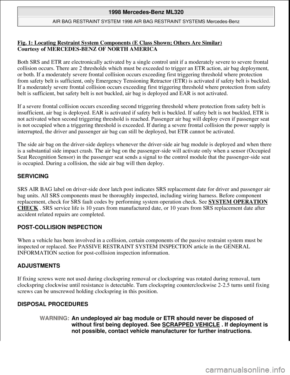
Fig. 1: Locating Restraint System Components (E Class Shown; Others Are Similar)
Courtesy of MERCEDES-BENZ OF NORTH AMERICA
Both SRS and ETR are electronically activated by a single control unit if a moderately severe to severe frontal
collision occurs. There are 2 thresholds which must be exceeded to trigger an ETR action, air bag deployment,
or both. If a moderately severe frontal collision occurs exceeding first triggering threshold where protection
from safety belt is sufficient, only Emergency Tensioning Retractor (ETR) is activated if safety belt is buckled.
If a moderately severe frontal collision occurs exceeding first triggering threshold where protection from safety
belt is sufficient, but safety belt is not buckled, air bag is deployed and EAR is not activated.
If a severe frontal collision occurs exceeding second triggering threshold where protection from safety belt is
insufficient, air bag is deployed. EAR is activated if safety belt is buckled. If safety belt is not buckled, ETR is
not activated when second triggering threshold is reached. Passenger air bag will deploy even if passenger seat
is not occupied when a triggering threshold is exceeded. If during a severe frontal collision the power supply is
interrupted, the driver and passenger air bag can still be deployed, but ETR cannot be activated.
The side air bag on the driver-side deploys whenever the driver-side air bag module is deployed and when there
is a substantial side impact crash. The air bag on the passenger-side will activate only when a sensor (Occupied
Seat Recognition Sensor) in the passenger seat sends a signal to the control module that the passenger-side seat
is occupied. During a collision, the side air bag will then deploy.
SERVICING
SRS AIR BAG label on driver-side door latch post indicates SRS replacement date for driver and passenger air
bag units. All SRS components must be thoroughly inspected, including wiring harness. Before component
replacement, check for SRS fault codes by performing system operation check. See SYSTEM OPERATION
CHECK . SRS service life is 10 years from manufactured date, or 10 years from SRS replacement date after
accident related repairs are completed.
POST-COLLISION INSPECTION
When a vehicle has been involved in a collision, certain components of the passive restraint system must be
inspected or replaced. See PASSIVE RESTRAINT SYSTEM INSPECTION article in the GENERAL
INFORMATION section for post-collision inspection information.
ADJUSTMENTS
If fixing screws were not used during clockspring removal or clockspring was rotated during removal, turn
clockspring clockwise until resistance is detectable. Turn clockspring counterclockwise 2-2.5 turns until fixing
screws can be unscrewed holding clockspring in this position.
DISPOSAL PROCEDURES
WARNING:An undeployed air bag module or ETR should never be disposed of
without first being deployed. See SCRAPPED VEHICLE
. If deployment is
not possible, contact vehicle manufacturer for further instructions.
1998 Mercedes-Benz ML320
AIR BAG RESTRAINT SYSTEM 1998 AIR BAG RESTRAINT SYSTEMS Mercedes-Benz
me
Saturday, October 02, 2010 3:33:13 PMPage 3 © 2006 Mitchell Repair Information Company, LLC.
Page 9 of 4133
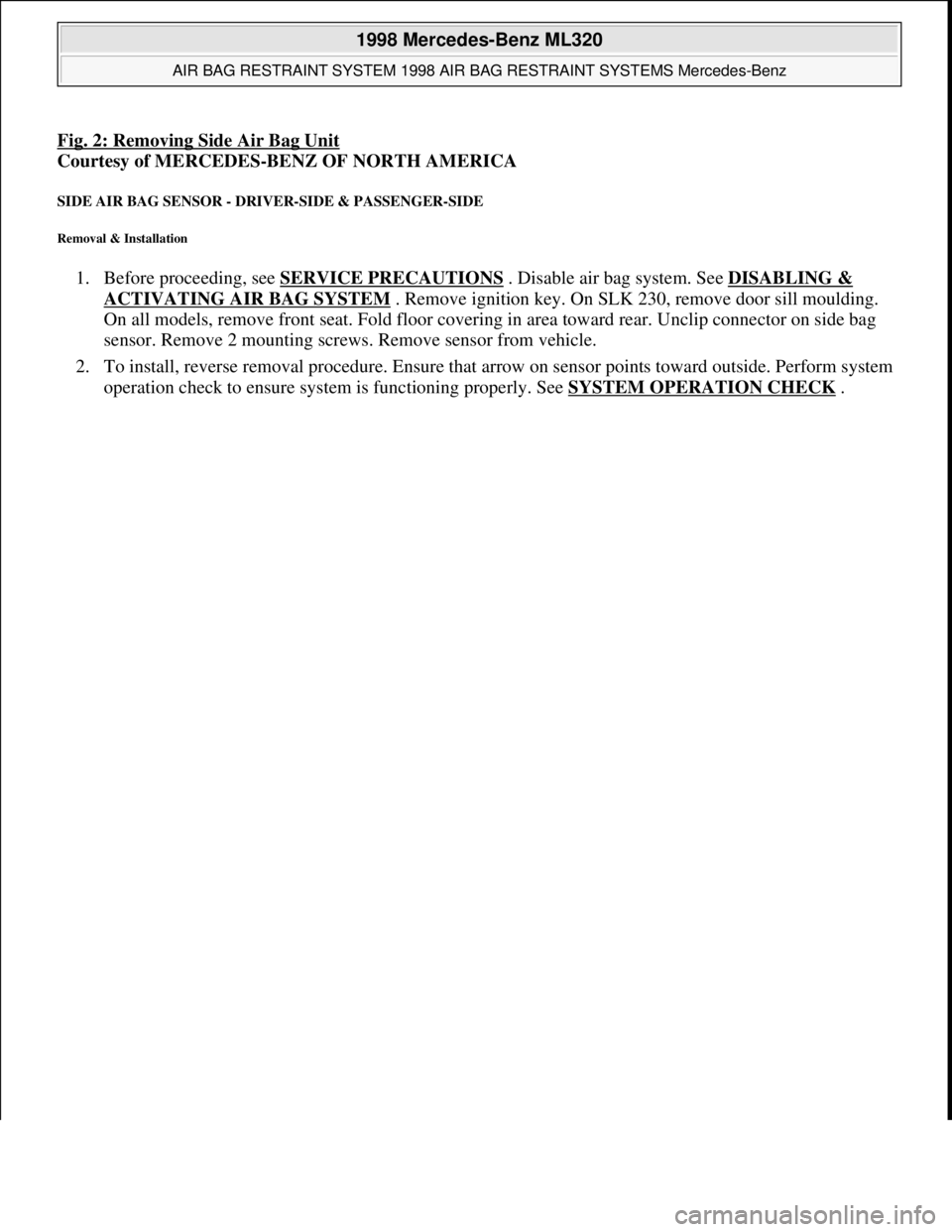
Fig. 2: Removing Side Air Bag Unit
Courtesy of MERCEDES-BENZ OF NORTH AMERICA
SIDE AIR BAG SENSOR - DRIVER-SIDE & PASSENGER-SIDE
Removal & Installation
1. Before proceeding, see SERVICE PRECAUTIONS . Disable air bag system. See DISABLING &
ACTIVATING AIR BAG SYSTEM . Remove ignition key. On SLK 230, remove door sill moulding.
On all models, remove front seat. Fold floor covering in area toward rear. Unclip connector on side bag
sensor. Remove 2 mounting screws. Remove sensor from vehicle.
2. To install, reverse removal procedure. Ensure that arrow on sensor points toward outside. Perform system
operation check to ensure system is functioning properly. See SYSTEM OPERATION CHECK
.
1998 Mercedes-Benz ML320
AIR BAG RESTRAINT SYSTEM 1998 AIR BAG RESTRAINT SYSTEMS Mercedes-Benz
me
Saturday, October 02, 2010 3:33:14 PMPage 9 © 2006 Mitchell Repair Information Company, LLC.
Page 20 of 4133
with HHT connected to DLC and ignition key removed. Remove driver-side air bag module. Disconnect
driver-side air bag module squib connector R12/3. Connect Resistance Substitution Unit (124 589 09 63)
to driver-side air bag module squib connector (harness side). Set resistance substitution unit to 2 ohms.
Turn ignition key to position "2". Read NOMINAL VALUE/HHT DISPLAY column. If HHT displays a
check, replace driver-side air bag module. If HHT displays an "F", go to step 3.2.
Read TEST CONNECTION (NOT FOR HHT) column. Horn/air bag clockspring connector A45x1,
terminals No. 1 and 2 are identified. Read TEST CONDITION column. Test circuit with HHT connected
to DLC. Remove ignition key. Connect Resistance Substitution Unit (124 589 09 63 00) to horn/air bag
clockspring connector A45x1. Set resistance substitution unit to 2 ohms. Read NOMINAL VALUE/HHT
DISPLAY column. If HHT displays a check, check horn/air bag clockspring for continuity. Replace
horn/air bag clockspring as necessary. If HHT displays an "F", go to step 3.4.
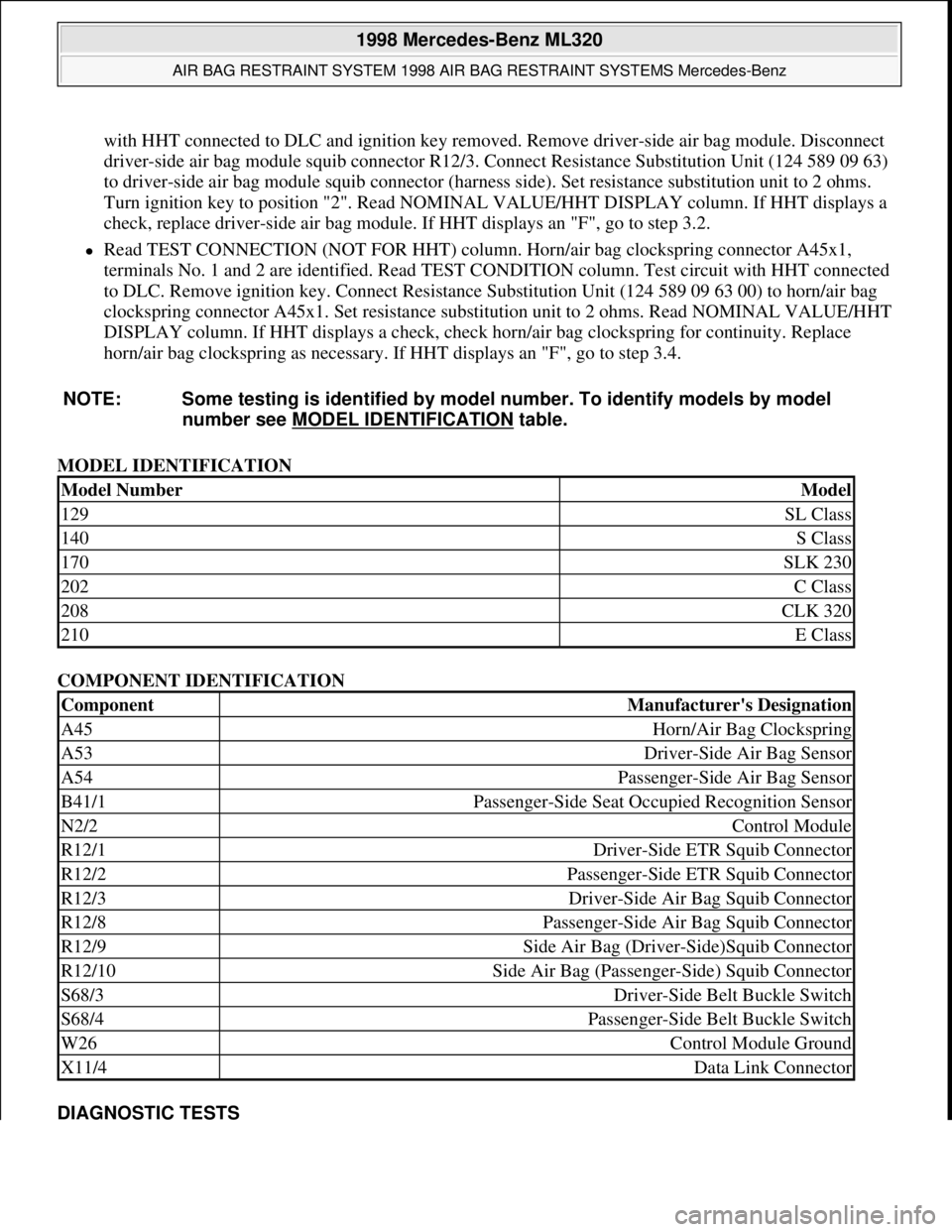
MODEL IDENTIFICATION
COMPONENT IDENTIFICATION
DIAGNOSTIC TESTS NOTE: Some testing is identified by model number. To identify models by model
number see MODEL IDENTIFICATION
table.
Model NumberModel
129SL Class
140S Class
170SLK 230
202C Class
208CLK 320
210E Class
ComponentManufacturer's Designation
A45Horn/Air Bag Clockspring
A53Driver-Side Air Bag Sensor
A54Passenger-Side Air Bag Sensor
B41/1Passenger-Side Seat Occupied Recognition Sensor
N2/2Control Module
R12/1Driver-Side ETR Squib Connector
R12/2Passenger-Side ETR Squib Connector
R12/3Driver-Side Air Bag Squib Connector
R12/8Passenger-Side Air Bag Squib Connector
R12/9Side Air Bag (Driver-Side)Squib Connector
R12/10Side Air Bag (Passenger-Side) Squib Connector
S68/3Driver-Side Belt Buckle Switch
S68/4Passenger-Side Belt Buckle Switch
W26Control Module Ground
X11/4Data Link Connector
1998 Mercedes-Benz ML320
AIR BAG RESTRAINT SYSTEM 1998 AIR BAG RESTRAINT SYSTEMS Mercedes-Benz
me
Saturday, October 02, 2010 3:33:14 PMPage 20 © 2006 Mitchell Repair Information Company, LLC.
Page 69 of 4133
19 Instruments and controls
Te ch n ica l
data Instruments
and controlsOperation DrivingInstrument
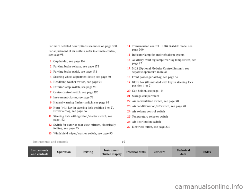
cluster displayPractical hints Car care Index For more detailed descriptions see index on page 300.
For adjustment of air outlets, refer to climate control,
see page 98.
1Cup holder, see page 114
2Parking brake release, see page 173
3Parking brake pedal, see page 173
4Steering wheel adjustment lever, see page 70
5Headlamp washer switch, see page 94
6Exterior lamp switch, see page 90
7Cruise control switch, see page 196
8Instrument cluster, see page 76
9Hazard warning flasher switch, see page 94
10Horn (with key in steering lock position 1 or 2),
Driver airbag, see page 56
11Steering lock with ignition / starter switch, see
page 162
12Switch for exterior rear view mirrors, electrically
folding, see page 75
13Windshield wiper / washer switch, see page 9514Transmission control – LOW RANGE mode, see
page 209
15Indicator lamp for antitheft alarm system
16Auxiliary front fog lamp / rear fog lamp switch, see
page 92
17MCS (Optional Modular Control System), see
separate operator’s manual
18Front passenger airbag, see page 56
19Glove box (illuminated with key in steering lock
position 1 or 2)
20Cup holder, see page 114
21Storage compartment
22Air recirculation switch, see page 98
23Air conditioner on /off switch, see page 98
24Air volume control switch
25Temperature selector switch
26Air distribution switch
27Electrical outlet, see page 230
Page 90 of 4133
40 Seats
Te ch n ica l
data Instruments
and controlsOperationDrivingInstrument
cluster displayPractical hints Car care Index
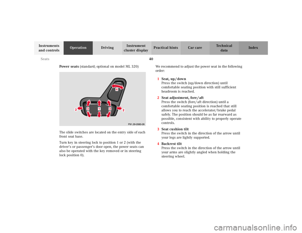
Power seats (standard; optional on model ML 320)
The slide switches are located on the entry side of each
front seat base.
Turn key in steering lock to position 1 or 2 (with the
driver’s or passenger’s door open, the power seats can
also be operated with the key removed or in steering
lock position 0).We recommend to adjust the power seat in the following
order:
1Seat, up / down
Press the switch (up/down direction) until
comfortable seating position with still sufficient
headroom is reached.
2Seat adjustment, fore / aft
Press the switch (fore / aft direction) until a
comfortable seating position is reached that still
allows you to reach the accelerator / brake pedal
safely. The position should be as far rearward as
possible, consistent with ability to properly operate
controls.
3Seat cushion tilt
Press the switch in the direction of the arrow until
your legs are lightly supported.
4Backrest tilt
Press the switch in the direction of the arrow until
your arms are slightly angled when holding the
steering wheel.
Page 108 of 4133
58 Restraint systems
Te ch n ica l
data Instruments
and controlsOperationDrivingInstrument
cluster displayPractical hints Car care Index
out after approximately 5 seconds; after the lamp goes
out, the system continues to monitor the components
and circuitry of the airbag system and will indicate a
malfunction by coming on again. If the lamp does not
come on at all or if it fails to extinguish after
approximately 5 seconds or if it comes on thereafter,
a malfunction in the system has been detected.
The following system components are monitored or
undergo a self-check: crash-sensor(s), airbag ignition
circuits, front seat belt buckles, emergency tensioning
retractors, seat sensor.
Initially, when the key is turned from steering lock
position 0 to positions 1 or 2, malfunctions in the
crash-sensor are detected and indicated (the “SRS”
indicator lamp stays on longer than 5 seconds or does
not come on).
Have the system checked at your authorized
Mercedes-Benz Light Truck Center immediately.In the operational mode, after the indicator lamp has
gone out following the initial check, interruptions or
short circuits in the airbag ignition circuit and in the
driver and front passenger seat belt buckle harnesses,
and low voltage in the entire system are detected and
indicated.
Wa r n i n g !
In the event a malfunction of the “SRS” is indicated
as outlined above, the “SRS” may not be
operational. For your safety, we strongly
recommend that you visit an authorized
Mercedes-Benz Light Truck Center immediately to
have the system checked; otherwise the “SRS” may
not be activated when needed in an accident, which
could result in serious or fatal injury, or it might
deploy unexpectedly and unnecessarily which
could also result in injury.
Page 136 of 4133
86 Trip computer
Te ch n ica l
data Instruments
and controlsOperationDrivingInstrument
cluster displayPractical hints Car care Index
To calibrate the compass:
If the vehicle was exposed to a significant magnetic
zone, such as high voltage power lines, the compass
may have to be calibrated.
Calibration of the compass should be done in an area
free of steel superstructures and power lines. All
electrical consumers (e.g. exterior lamps, climate
control, etc.) should be switched off, doors and liftgate
closed. Do not open or close the roof. An open door or
liftgate triggers the display “–––”.
1. Start and run the engine.
2. Press MODE key repeatedly until the compass
display appears in the trip computer display.
3. Press RESET key to select the compass zone display.
4. Press RESET repeatedly until the correct zone, as
determined from the zone map (see page 85), is
shown in the display.
5. Press MODE key, “CAL–” appears in the display.
6. Press and hold RESET for a minimum of 2 seconds.7. Without interruption drive two or more full circles
at a speed between 3 mph (5 km / h) and 7 mph
(10 km / h) during which the message “CAL” is
replaced with a compass bearing (e.g. N, SW etc.),
immediately followed by three full circles at the
same speed, with only the rear window defroster
switched on. The defroster can be switched off
again. The calibration of the compass is now
complete.
•Stop watch –
Press RESET key to start the count. Press again to
stop the count. Press and hold RESET key to reset
sto p watch.
•Average fuel consumption –
Press RESET key to delete present reading.
•Language –
Press RESET key to set the language used in the
display.