1997 MERCEDES-BENZ ML320 Drive Mode
[x] Cancel search: Drive ModePage 237 of 4133
187 Driving instructions
Te ch n ica l
data Instruments
and controlsOperationDrivingInstrument
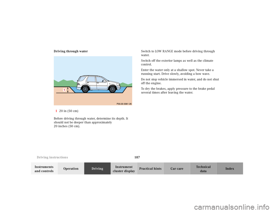
cluster displayPractical hints Car care Index Driving through water
120 in (50 cm)
Before driving through water, determine its depth. It
should not be deeper than approximately
20 inches (50 cm).Switch to LOW RANGE mode before driving through
water.
Switch off the exterior lamps as well as the climate
control.
Enter the water only at a shallow spot. Never take a
running start. Drive slowly, avoiding a bow wave.
Do not stop vehicle immersed in water, and do not shut
off the engine.
To dry the brakes, apply pressure to the brake pedal
several times after leaving the water.
Page 239 of 4133
189 Driving instructions
Te ch n ica l
data Instruments
and controlsOperationDrivingInstrument
cluster displayPractical hints Car care Index Returning from off-road driving
Off-road driving increases strain on the vehicle.
We recommend that you inspect the vehicle for possible
damage after each off-road trip. Recognizing any
damage and a subsequent timely repair reduces the
chance of a possible breakdown or accident later on.
Proceed as follows:
•Switch off the LOW RANGE mode, see page 209.
•Remove excessive dirt from tires, wheels, wheel
housings, and underbody. For instance, after driving
in mud, clean the radiator, chassis, engine, brakes,
and wheels from extreme dirt, using a strong jet of
water.
•Inspect frame, oil pan, brake hoses, etc., as well as
vehicle underbody for possible damage.
•Check tires for possible damage, clean all exterior
lamps, and conduct a brake test.•Check for brush or branches caught in the
undercarriage. They could increase the possibility of
a fire, as well as cut fuel and / or brake lines,
puncture rubber bellows of the axles or drive shafts.
Wa r n i n g !
If you feel a sudden significant vibration or ride
disturbance, or you suspect that possible damage to
your vehicle has occurred, you should turn on the
hazard warning flashers, carefully slow down, and
drive with caution to an area which is a safe
distance from the roadway.Inspect the tires and under the vehicle for possible
damage. If the vehicle or tires appear unsafe, have
it towed to the nearest Mercedes-Benz Light Truck
Center or tire dealer for repairs.
Page 252 of 4133
202 Driving systems
Te ch n ica l
data Instruments
and controlsOperationDrivingInstrument
cluster displayPractical hints Car care Index
If the charging voltage falls below 10 volts, the
malfunction indicator lamp comes on and the ABS is
switched off. When the voltage is above this value again,
the malfunction indicator lamp should go out and the
ABS is operational.
If the ABS malfunction indicator lamp stays illuminated,
have the system checked at your authorized
Mercedes-Benz Light Truck Center as soon as possible.Notes:
To alert following vehicles to slippery road conditions
you discover, operate your hazard warning flashers as
appropriate.
Operating the vehicle on a single axle dynamometer
should only be done for briefly testing the brakes. To do
so, move selector lever to position “N”. The engine must
be shut off (key in steering lock position 0 or 1).
LOW RANGE – ABS
During off-road driving a special low range system for
the antilock brake system (ABS) is operational with
transmission in LOW RANGE mode, see page 211.
When applying the service brakes at speeds below
approximately 18 mph (30 km / h), the front wheels are
locked cyclically to shorten the braking distance (dig in
effect). This affects steering the vehicle.
Wa r n i n g !
ABS cannot prevent the natural laws of physics
from acting on the vehicle, nor can it increase
braking or steering efficiency beyond that afforded
by the condition of the vehicle brakes and tires or
the traction afforded. The ABS cannot prevent
accidents, including those resulting from excessive
speed in turns, following another vehicle too
closely, or aquaplaning. Only a safe, attentive, and
skillful driver can prevent accidents. The
capabilities of an ABS equipped vehicle must never
be exploited in a reckless or dangerous manner
which could jeopardize the user’s safety or the
safety of others.
Page 258 of 4133
208 Driving systems
Te ch n ica l
data Instruments
and controlsOperationDrivingInstrument
cluster displayPractical hints Car care Index
If one drive wheel loses traction and begins to spin, the
brake is applied until the wheel regains sufficient
traction.
Note:
Avoid spinning of one drive wheel. This may cause
serious damage to the drive train which is not covered
by the Mercedes-Benz Limited Warranty.
The ESP warning lamp, located in the speedometer dial,
starts to f lash at any vehicle speed as soon as the tires
lose traction and the wheels begin to spin.
To return to the enhanced vehicle stability offered by
ESP: press lower half of the switch (the ESP warning
lamp in the speedometer dial goes out).
Important!
If the ESP warning lamp f lashes:
•during take-off, apply as little throttle as possible,
•while driving, ease up on the accelerator.LOW RANGE – ESP
During off-road driving a special low range system for
the electronic stability program (ESP) is operational
with transmission in LOW RANGE mode, see page 211.
In the LOW RANGE mode the electronic stability
program (ESP) operates in a traction improving fashion
specifically adapted for off-road driving. At speeds
below 27 mph (45 km / h) the ESP assists in over-/
understeering, thus improving vehicle tracking.
Page 261 of 4133
211 Driving systems
Te ch n ica l
data Instruments
and controlsOperationDrivingInstrument
cluster displayPractical hints Car care Index Important!
During off-road driving a special low range system for
antilock brake system (ABS) and four-wheel electronic
traction system (4-ETS+) are operational with
transmission in the LOW RANGE mode.
In the low range mode the electronic stability program
(ESP) operates in a traction improving fashion
specifically adapted for off-road driving. At speeds
below 27 mph (45 km / h) the ESP assists in over- /
understeering, thus improving vehicle tracking.
If one or more tires lose traction while driving downhill
(accelerator released), the 4-ETS+ engages and the
warning lampv, located in the speedometer dial,
starts to f lash.
When applying the service brakes at speeds below
approximately 18 mph (30 km / h), the front wheels are
locked cyclically to shorten the braking distance (dig in
effect). This affects steering the vehicle.Notes:
Driving off or driving up to 3 mph (5 km / h) with the
service brakes applied lightly (to reduce drive wheel
spin), the 4-ETS+ remains engaged. Driving with the
service brakes applied lightly at vehicles speeds above
3 mph (5 km / h), the 4-ETS+ will not engage.
If the indicator lamp blinks fast, one or more switching
conditions were not observed, or the LOW RANGE mode
is defective.
In the case of a defective in the LOW RANGE mode the
transmission shifts in the usual manner. It is not
possible to switch on the LOW RANGE mode.
Have the transmission checked at your authorized
Mercedes-Benz Light Truck Center as soon as possible.
Page 322 of 4133
272 Emergency operation of sliding/pop-up roof
Te ch n ica l
data Instruments
and controlsOperation DrivingInstrument
cluster displayPractical hintsCar care Index
Emergency operation of sliding/pop-up roof
The sliding / pop-up roof can be opened or closed
manually should an electrical malfunction occur.
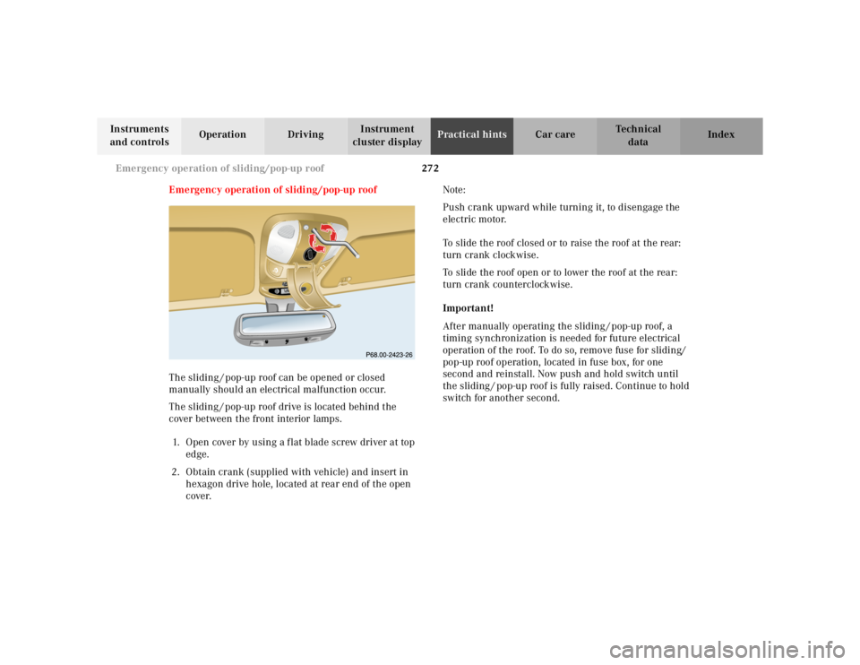
The sliding / pop-up roof drive is located behind the
cover between the front interior lamps.
1. Open cover by using a f lat blade screw driver at top
edge.
2. Obtain crank (supplied with vehicle) and insert in
hexagon drive hole, located at rear end of the open
cover.Note:
Push crank upward while turning it, to disengage the
electric motor.
To slide the roof closed or to raise the roof at the rear:
turn crank clockwise.
To slide the roof open or to lower the roof at the rear:
turn crank counterclockwise.
Important!
After manually operating the sliding / pop-up roof, a
timing synchronization is needed for future electrical
operation of the roof. To do so, remove fuse for sliding/
pop-up roof operation, located in fuse box, for one
second and reinstall. Now push and hold switch until
the sliding / pop-up roof is fully raised. Continue to hold
switch for another second.
RESETMODEMODE
Page 360 of 4133
310 Index
Te ch n ica l
data Instruments
and controlsOperation DrivingInstrument
cluster displayPractical hints Car careIndex
Tires
Driving instructions ................................................. 177
Rims and tires ...........................................................288
Rotating wheels ......................................................... 241
Tire inflation pressure .............................................250
Tire replacement .......................................................240
Winter driving instructions .................................... 180
Tow-away alarm ................................................................ 36
Switching off ................................................................ 36
Towing the vehicle .........................................................255
Stranded vehicle .......................................................259
Transmission selector lever, manually unlocking 259
Trailer operation ............................................................ 198
Trailer towing ................................................................. 190
Transmission .................................................................. 165
Transmission control - LOW RANGE mode ...............209
Transmission fluid level ...............................................234
Transmission selector lever, manually unlocking ....259
Traveling abroad ............................................................ 182
Trip computer ................................................................... 83
Trip odometer ................................................................... 80
Trunk ................................................................................. 34
Opening ........................................................................ 28
Trunk lamp ...................................................................... 111Turn signal failure ........................................................... 91
Turn signal lamp, side .................................................. 266
Turn signals ......................................................................90
UUnlocking the vehicle ...................................................... 27VVanity mirrors ................................................................ 113
Vehicle jack .................................................................... 237
Vehicle keys ......................................................................24
Ve h i c l e t o o l s
Screwdriver ............................................................... 237WWarranty coverage ........................................................ 284
Washing the vehicle ..................................................... 280
What you should know at the gas station .................. 212
Wheel bolt wrench ........................................................ 237
Wheels ............................................................................ 240
Changing wheels ...................................................... 245
Page 365 of 4133
2000-01 ACCESSORIES/SA FETY EQUIPMENT
Mercedes-Benz - Air Bag Restraint Systems
DESCRIPTION & OPERATION
All models are equipped with Supplemental Restraint Syst em (SRS). The main components of SRS are driver-
side air bag module, passenger-side air bag module, si de air bag modules (located in doors), SRS control
module, side air bag sensors, SRS warning light, driver knee bolster, pa ssenger knee bolster, and Emergency
Tensioning Retractor (ETR) seat belt assembly. Additionally, some vehicles may be equipped with head impact
(curtain type) air bags (located ar ound door windows behind door frame trims).
Both SRS and ETR are electronically activated by a single control module. There are 2 thresholds which must
be exceeded to trigger an ETR acti on, air bag deployment, or both. If a moderately severe frontal collision
occurs exceeding first triggering thre shold where protection from safety belt is sufficient, only Emergency
Tensioning Retractor (ETR) is activated if safety belt is buckled. If a moderately severe frontal collision occurs
exceeding first triggering threshold where protection from safety belt is sufficient, but safety belt is not buckled,
air bag is deployed and ETR is not activated.
If a severe frontal collision occurs exceeding second triggering threshold where protection from safety belt is
insufficient, air bag is deploye d. ETR is activated if safety belt is buckled. If safety belt is not buckled, ETR is
not activated when second triggering threshold is reached. Passenger air bag will deploy even if passenger seat
is not occupied when a triggering thre shold is exceeded. If during a severe frontal collision the power supply is
interrupted, the driver and passenger air bag can still be deployed, but ETR cannot be activated.
The side air bag on the driver-side deploys whenever th e driver-side air bag module is deployed and when there
is a substantial side impact crash. The air bag on the pa ssenger-side will activate only when a sensor (Occupied
Seat Recognition Sensor) in the passenger seat sends a si gnal to the SRS control module that the passenger-side
seat is occupied. During a collision, the side air bag will then deploy.
COMPONENT LOCATIONS NOTE: The following 2000 in
formation represents the latest information available at
time of publication and m ay be useful in diagnosing 2001 vehicles. 2001 wiring
diagrams have been included at the end of this article.
WARNING: Accidental air bag deployment is pos sible. Personal injury may result.
Read and follow all WARNINGS and AIR BAG SAFETY PRECAUTIONS
before working on ai r bag system or related components.
2001 Mercedes-Benz ML320
2000-01 ACCESSORIES/SAFETY EQUIPMENT Merc edes-Benz - Air Bag Restraint Systems
2001 Mercedes-Benz ML320
2000-01 ACCESSORIES/SAFETY EQUIPMENT Mercedes-Benz - Air Bag Restraint Systems
me
Saturday, October 02, 2010 3:44:44 PMPage 1 © 2006 Mitchell Repair Information Company, LLC.
me
Saturday, October 02, 2010 3:44:49 PMPage 1 © 2006 Mitchell Repair Information Company, LLC.