Page 564 of 1600

7C-24 CLUTCH
Wedge Collar (6VD1)
1. Visually check the surfaces of the wedge collar making
contact with the release bearing for excessive wear and
damage.
2. Replace any exhibiting excessive wear damage.
Shift Fork (Except 6VD1)
1. Visually inspect the surfaces of the shift fork making contact
with the shift block for excessive wear and damage.
2. Remove any minor stepping or abrasion from the shift block
with an oil stone.
Replace any exhibiting excessive wear or damage.
3. Apply multi-purpose type grease (NLGI No.2 or No.3) to
area.
6VD1Shift Fork (6VD1)
1. Visually check the surfaces of the shift fork making contact
with the release bearing for excessive wear and damage.
2. Remove any minor stepping or abrasion from shift fork with
an oil stone.
Replace any exhibiting excessive wear of damage.
DRIVEN PLATE ASSEMBLY
1. Visually inspect the torsion spring
1 for looseness,
breakage, and weakening.
If any of these conditions are discovered, the driven plate
assembly must be replaced.
2. Visually inspect the facing surfaces
2 for cracking and
excessive scorching.
Visually inspect the facing surfaces for the presence of oil or
grease.
If any of these conditions are discovered, the facing must be
cleaned or replaced.
Page 565 of 1600

CLUTCH 7C-25
3. Check that the driven plate moves smoothly on the
transmission top gear shaft spline.
Minor ridges on the top gear shaft spline may be removed
with an oil stone.
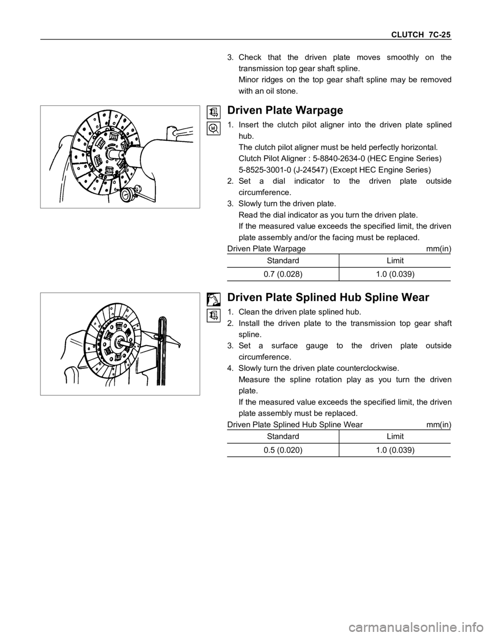
Driven Plate Warpage
1. Insert the clutch pilot aligner into the driven plate splined
hub.
The clutch pilot aligner must be held perfectly horizontal.
Clutch Pilot Aligner : 5-8840-2634-0 (HEC Engine Series)
5-8525-3001-0 (J-24547) (Except HEC Engine Series)
2. Set a dial indicator to the driven plate outside
circumference.
3. Slowly turn the driven plate.
Read the dial indicator as you turn the driven plate.
If the measured value exceeds the specified limit, the driven
plate assembly and/or the facing must be replaced.
Driven Plate Warpage mm(in)
Standard Limit
0.7 (0.028) 1.0 (0.039)
Driven Plate Splined Hub Spline Wear
1. Clean the driven plate splined hub.
2. Install the driven plate to the transmission top gear shaft
spline.
3. Set a surface gauge to the driven plate outside
circumference.
4. Slowly turn the driven plate counterclockwise.
Measure the spline rotation play as you turn the driven
plate.
If the measured value exceeds the specified limit, the driven
plate assembly must be replaced.
Driven Plate Splined Hub Spline Wear mm(in)
Standard Limit
0.5 (0.020) 1.0 (0.039)
Page 570 of 1600
7C-30 CLUTCH
MASTER CYLINDER (Except 6VD1 Engine)
DISASSEMBLY
Repair Kit
Disassembly Steps
1. Oil tank band
2. Oil tank assembly
3. Joint
4. Lock nut
5. Dust cover6. Stopper ring
7. Stopper
8. Push rod
9. Piston assembly
10. Cylinder body
Important : Take care not to disassemble the push rod stopper for master cylinder which calk to the master cylinder
body due to the component parts do not disassemble.
Page 572 of 1600
7C-32 CLUTCH
REASSEMBLY
* Apply grease
(COSMO rubber grease)
Repair Kit
Reassembly Steps
1. Cylinder body
2. Piston and assembly
3. Push rod
4. Stopper
5. Stopper ring6. Dust cover
7. Lock nut
8. Joint
9. Oil tank assembly
10. Oil tank band
Important Operations
1. Cylinder Body
Immerse the cylinder body in clean brake fluid.
Page 582 of 1600
7C-42 CLUTCH
1. CLUTCH SLIPPAGE
Checkpoint Trouble Cause Countermeasure
Adjust the push rod playNo push rod play in the master
cylinder NG
Clean the related parts and/or
replace the facing
Replace the transmission front
cover oil seal
Clean the related parts and/or
replace the facing
Repair or replace the
transmission front cover
Adjust the push rod play
Defective transmission front
cover oil seal
Continued on the next page
Grease or oil adhering to the
facingToo much grease
Transmission front cover
unevenly worn
No push rod play in the slave
cylinder
Clean and grease the shift
blockShift blockInsufficient grease on the front
cover contact surfaces
NG NG NG NG NG
OK
OK
Clutch pedal free play
OK