Page 97 of 1600

4C1-34 FRONT WHEEL DRIVE
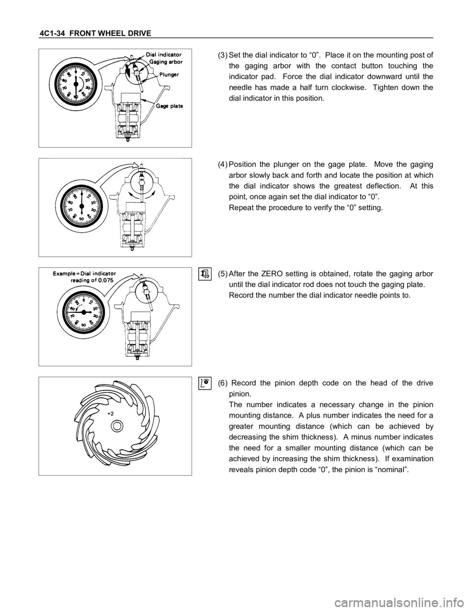
(3) Set the dial indicator to “0”. Place it on the mounting post of
the gaging arbor with the contact button touching the
indicator pad. Force the dial indicator downward until the
needle has made a half turn clockwise. Tighten down the
dial indicator in this position.
(4) Position the plunger on the gage plate. Move the gaging
arbor slowly back and forth and locate the position at which
the dial indicator shows the greatest deflection. At this
point, once again set the dial indicator to “0”.
Repeat the procedure to verify the “0” setting.
(5) After the ZERO setting is obtained, rotate the gaging arbor
until the dial indicator rod does not touch the gaging plate.
Record the number the dial indicator needle points to.
(6) Record the pinion depth code on the head of the drive
pinion.
The number indicates a necessary change in the pinion
mounting distance. A plus number indicates the need for a
greater mounting distance (which can be achieved by
decreasing the shim thickness). A minus number indicates
the need for a smaller mounting distance (which can be
achieved by increasing the shim thickness). If examination
reveals pinion depth code “0”, the pinion is “nominal”.
Page 344 of 1600

5-16 BRAKES
From
primary
master cylinder From
Secondary
master cylinder
Operation
1) Outline
W hen the L.S.P.V.(Load Sensing Proportioning Valve)
detects a change in load weight, the load sensing spring
deflects.
Its reaction force is transmitted to the bottom of the load
sensing valve to secure an optimum rear wheel cylinder
fluid pressure break point in proportion to the actual load
weight.
Besides, if the front brake system should fail, the device is
designed to prevent the master cylinder fluid pressure from
decreasing and to apply it directly to the rear wheel cylinder
to obtain a sufficient braking performance.
Primary master
cylinder fluid
pressure Secondary master
cylinder fluid
pressure
2) Operation
(1) When the fluid pressure is under the break point.
The fluid pressure of the rear master cylinder passes
through a clearance between the valve seal and the piston
and acts on the rear wheel cylinder.
At this moment, a downward force is applied to the piston.
However, the compression spring force and reaction force
of the load sensing spring keep the piston in the upper
position by pushing upwards. (See the left figure.)
Primary master
cylinder fluid
pressure Secondary master
cylinder fluid
pressure
(2) When the fluid pressure is equal to the break point.
As the rear wheel cylinder pressure increases, it surpasses
the compression spring force and reaction force of the load
sensing spring, causing the piston to move downwards, so
that the piston butts against the valve seal to shut off the
fluid line between the master cylinder and rear wheel
cylinder. (See the left figure.)
(3) When the fluid pressure is over the break point.
W hen the fluid pressure increases further, the piston moves
upwards.
The moment the piston comes apart from the valve seal,
fluid pressure is applied to the rear wheel cylinder and the
piston moves downwards so that the fluid line is shut off
again.
This process goes on repeatedly to control the fluid
pressure to the rear wheel cylinder.
Page 349 of 1600

BRAKES 5-21
Operation
The operation of the P-valve by the master cylinder
pressure is unchanged up to the brake points
A and B.
If master cylinder fluid pressure penetrates into the second
break point
B, the fluid pressure pressing against the seal
2, (which isolated route 4 and route 5), passing the route
4 of the master cylinder side, overcomes the operating
force of the spring
3 + fluid pressure affecting the seal 2 of
the wheel cylinder, and presses the piston
1 to the right
side, resulting in the opening of the routes
4 and 5, and
canceling of the P-valve operation.
Then, because the master cylinder fluid pressure and the
wheel cylinder fluid pressure, up to the point
C, operate on
the identical surface of the seal
2, both have identical
ascending ratio.
However, because of the operation of spring
3 in the wheel
cylinder side, wheel cylinder fluid pressure operate to
preserve the balance against the master cylinder fluid
pressure on the lower level with the difference in pressure
resulting from this spring.
Valve Maintenance
In the case of fluid leak or other abnormalities, faulty valve
should be replaced.
The valve is set up at the right hand side of the 5th
crossmember near the rear axle.
Note:
The blend proportioning valve is not repairable and must
be replaced as a complete assembly.
BLEEDING OF THE BRAKE HYDRAULIC
CIRCUIT
If air enters the bake lines, it will cause poor brake action.
Therefore, bleeding should be performed if the brakes have
been used with the level of brake fluid in the reservoir
excessively low or if brake pipes have been disconnected in
the course of brake servicing.
Bleeding operation calls for co-operative action of 2 persons.
Set the parking brake firmly while bleeding.
Perform bleeding operation with ENGINE RUNNING, to
prevent damage to push rod seal.
Make sure exhaust is suitably ventilated.
Bleed the hydraulic system with the fluid reservoir filled to
the specified level.
Bleed the system starting with the rear wheel cylinder
farthest from the master cylinder.
A : Load sensing proportioning valve (If so equipped).