Page 5 of 1600
REAR AXLE 4B-9
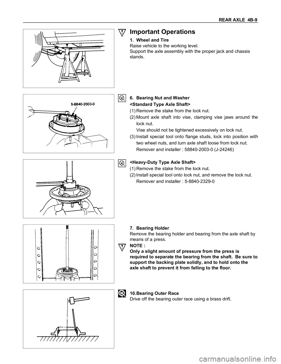
Important Operations
1. Wheel and Tire
Raise vehicle to the working level.
Support the axle assembly with the proper jack and chassis
stands.
6. Bearing Nut and Washer
(1) Remove the stake from the lock nut.
(2) Mount axle shaft into vise, clamping vise jaws around the
lock nut.
Vise should not be tightened excessively on lock nut.
(3) Install special tool onto flange studs, lock into position with
two wheel nuts, and turn axle shaft loose from lock nut.
Remover and installer : 58840-2003-0 (J-24246)
(1) Remove the stake from the lock nut.
(2) Install special tool onto lock nut, and remove the lock nut.
Remover and installer : 5-8840-2329-0
7. Bearing Holder
Remove the bearing holder and bearing from the axle shaft by
means of a press.
NOTE :
Only a slight amount of pressure from the press is
required to separate the bearing from the shaft. Be sure to
support the backing plate solidly, and to hold onto the
axle shaft to prevent it from falling to the floor.
10.Bearing Outer Race
Drive off the bearing outer race using a brass drift.
Page 395 of 1600
BRAKES 5-67
TROUBLESHOOTING
Condition and Cause Correction
Poor Brake Action
Master cylinder faulty Correct or replace
Power cylinder faulty Correct or replace
Level of brake fluid in reservoir too low Replenish and bleed
Air in hydraulic circuit Bleed
Front disc brake caliper faulty Clean or replace
Rear brake wheel cylinder faulty Clean or replace
Water or oil on brake pads or linings Clean or replace
Brake pads or linings hardened Replace
Brake pads or linings in poor contact with rotor or brake drum Correct
Brake pads or linings worn Replace
Brake disc or drum rusted Grind or replace
Check valve in vacuum hose faulty Correct or replace
Brake Squeak
Brake pads or linings worn Replace
Brake pads or linings hardened Replace
Brake pads or linings in poor contact with rotor or brake drum Correct
Brake disc(s) warped, worn or damaged Grind or replace
Disc brake anti-squeak shims fatigued Replace
Front hub bearings loose or preload is incorrect Adjust or replace
Brake disc or drum rusted Grind or replace
Brake Pull
Tire inflation pressures unequal Adjust
Front wheel alignment incorrect Adjust
Water or oil on brake pads or linings Clean or replace
Brake pads or linings hardened Replace
Brake pads or linings worn excessively Replace
Brake drum or rotor worn or scored Grind or replace
Front or rear wheel cylinder or disc brake caliper malfunctioning Clean or replace
Front hub bearing preload incorrect Adjust or replace
Brake pad or lining clearances unequal Adjust or replace
Brake Drag
Parking brake maladjusted Adjust
Brake pad or lining clearance insufficient Adjust
Brake pedal free play insufficient Adjust brake pedal height or power cylinder operating rod
Piston in master cylinder sticking Clean or replace
Pistons in disc brake caliper sticking Replace piston seals
Pistons in rear brake wheel cylinders sticking Clean or replace
Brake pads sticking in caliper Clean
Return springs weakened Replace
Parking brake binding Overhaul rear brakes
Front hub bearing preload incorrect Adjust or replace
Rear brake shoes not returning Correct or replace brake back plate, check automatic adjuster and
replace as necessary
Obstructions in hydraulic circuit Clean
Rotor warped excessively Grind or replace
Rear brake drum distorted Grind or replace
Piston cups swollen Replace brake fluid and piston cups
Check valve ; vacuum hose faulty Replace
Parking cable sticking Clean or replace
Rear disc brake over adjust Adjust or overhaul rear brakes
Excessive Brake Pedal Travel
Air in hydraulic circuit Bleed hydraulic circuit
Level of brake fluid in reservoir too low Replenish brake fluid reservoir to specified level and bleed hydraulic
circuit as necessary.
Master cylinder push rod clearance excessive Adjust
Leakage in hydraulic system Correct or replace defective parts
Rear disc brake autoadjuster malfunction Overhaul rear brakes
Page 465 of 1600
CAB 10-11
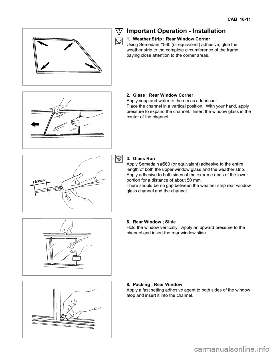
Important Operation - Installation
1. Weather Strip ; Rear Window Corner
Using Semedain #560 (or equivalent) adhesive, glue the
weather strip to the complete circumference of the frame,
paying close attention to the corner areas.
2. Glass ; Rear Window Corner
Apply soap and water to the rim as a lubricant.
Place the channel in a vertical position. With your hand, apply
pressure to expand the channel. Insert the window glass in the
center of the channel.
3. Glass Run
Apply Semedain #560 (or equivalent) adhesive to the entire
length of both the upper window glass and the weather strip.
Apply adhesive to both sides of the extreme ends of the lower
portion for a distance of about 50 mm.
There should be no gap between the weather strip rear window
glass channel and the channel.
6. Rear Window ; Slide
Hold the window vertically. Apply an upward pressure to the
channel and insert the rear window slide.
8. Packing ; Rear Window
Apply a fast setting adhesive agent to both sides of the window
atop and insert it into the channel.
Page 508 of 1600
CAB 10-11
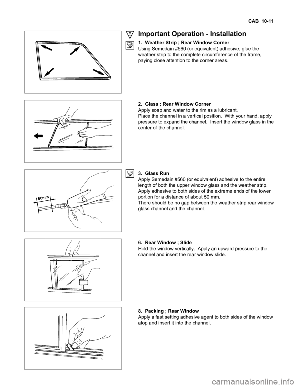
Important Operation - Installation
1. Weather Strip ; Rear Window Corner
Using Semedain #560 (or equivalent) adhesive, glue the
weather strip to the complete circumference of the frame,
paying close attention to the corner areas.
2. Glass ; Rear Window Corner
Apply soap and water to the rim as a lubricant.
Place the channel in a vertical position. With your hand, apply
pressure to expand the channel. Insert the window glass in the
center of the channel.
3. Glass Run
Apply Semedain #560 (or equivalent) adhesive to the entire
length of both the upper window glass and the weather strip.
Apply adhesive to both sides of the extreme ends of the lower
portion for a distance of about 50 mm.
There should be no gap between the weather strip rear window
glass channel and the channel.
6. Rear Window ; Slide
Hold the window vertically. Apply an upward pressure to the
channel and insert the rear window slide.
8. Packing ; Rear Window
Apply a fast setting adhesive agent to both sides of the window
atop and insert it into the channel.
Page 560 of 1600
7C-20 CLUTCH
INSPECTION AND REPAIR
Make the necessary adjustments, repairs, and part replacements if excessive wear or damage is discovered during
inspection.
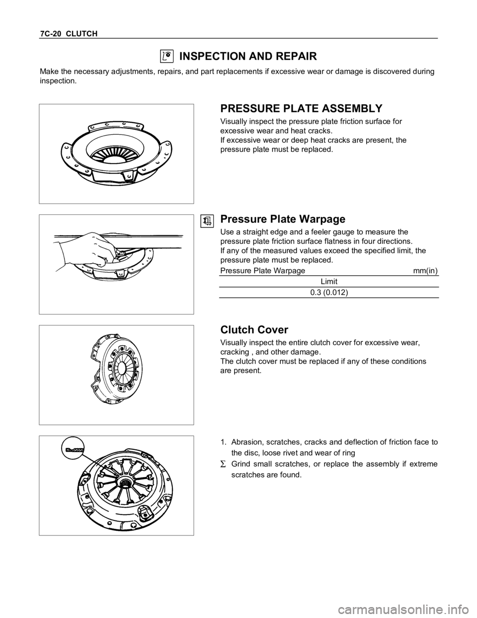
PRESSURE PLATE ASSEMBLY
Visually inspect the pressure plate friction surface for
excessive wear and heat cracks.
If excessive wear or deep heat cracks are present, the
pressure plate must be replaced.
Pressure Plate Warpage
Use a straight edge and a feeler gauge to measure the
pressure plate friction surface flatness in four directions.
If any of the measured values exceed the specified limit, the
pressure plate must be replaced.
Pressure Plate Warpage mm(in)
Limit
0.3 (0.012)
Clutch Cover
Visually inspect the entire clutch cover for excessive wear,
cracking , and other damage.
The clutch cover must be replaced if any of these conditions
are present.
1. Abrasion, scratches, cracks and deflection of friction face to
the disc, loose rivet and wear of ring
Grind small scratches, or replace the assembly if extreme
scratches are found.