Page 856 of 1503
Bearing Preload
Adjustment
If any of the items listed below are replaced, the bearing
preload must be adjusted.
• TRANSMISSION HOUSING
• CLUTCH HOUSING
• DIFFERENTIAL
• TAPERED ROLLER BEARING and OUTER RACE
• 75 mm THRUST SHIM
• 90 mm WASHER
• OIL GUIDE RING
1 . Remove the bearing outer race and 75 mm thrust
shim from the transmission housing by prying up
on the bearing outer race or by heating the housing
to about 212°F (100°C).
CAUTION: Do not reuse the thrust shim if the
outer race was pried out.
NOTE:
• If the outer race was removed by heating the
case, let the transmission cool to room tempera-
ture before adjusting the bearing preload.
• Do not heat the transmission housing in excess
of 212°F (100°C).
• Replace the bearing with a new one whenever
the outer race is replaced.
• Repeat on the clutch side.
BEARING OUTER
RACE
75 mm THRUST SHIM
Replace.
TRANSMISSION
HOUSINGProCarManuals.com
Page 866 of 1503
1. Install the clutch disc, clutch plate, central gear, and
carrier assembly. Lubricate the clutch disc surface
with transmission fluid.
CARRIER ASSEMBLY
CENTRAL GEAR
CLUTCH PLATE
CLUTCH DISC
DIFFERENTIAL
HOUSING
COVER
2. Install the final driven gear. Align the mark on the
differential housing cover with the mark on the final
driven gear.
FINAL
DRIVEN
GEAR
MARK
MARK
3. Install the 102 mm washer, clutch discs, clutch
plates, and 112 mm thrust shim. Lubricate the
clutch discs with transmission fluid. Position the
112 mm thrust shim with the thickness size mark
facing away from the clutch discs.
Thickness Size
Mark
CLUTCH PLATES
112 mm THRUST
SHIM
CLUTCH DISCS
102 mm WASHER
4. Install the 60 mm washer, spring plate, and stop
plate.
STOP PLATE
SPRING PLATE
60 mm WASHER
DIFFERENTIAL
HOUSING
Differential
ReassemblyProCarManuals.com
Page 869 of 1503
Oil Seal
Removal
1. Remove the differential assembly.
2. Remove the oil seal from the transmission housing.
OIL SEAL
Replace.
TRANSMISSION
HOUSING
3. Remove the oil seal from the torque converter
housing.
OIL SEAL
Replace.
TORQUE CONVERTER
HOUSINGProCarManuals.com
Page 871 of 1503
Bearing Preload
Adjustment
NOTE: If any of the items listed below are replaced, the
bearing preload must be adjusted.
TRANSMISSION HOUSING
TORQUE CONVERTER HOUSING
DIFFERENTIAL
TAPERED ROLLER BEARING and OUTER RACE
75 mm THRUST SHIM
90 mm WASHER
OIL GUIDE RING
1. Remove the bearing outer race and 75 mm thrust
shim from the transmission housing by prying up
on the bearing outer race or by heating the housing
to about 212°F (100°C).
CAUTION: Do not reuse the thrust shim if the
outer race was pried out.
NOTE:
• If the outer race was removed by heating the
case, let the transmission cool to room tempera-
ture before adjusting the bearing preload.
• Do not heat the transmission housing in excess
of 212°F (100°C).
• Replace the bearing with a new one whenever
the outer race is replaced.
• Repeat on the torque converter side.
BEARING OUTER
RACE
TRANSMISSION
HOUSING
75 mm THRUST SHIM
Replace.ProCarManuals.com
Page 904 of 1503

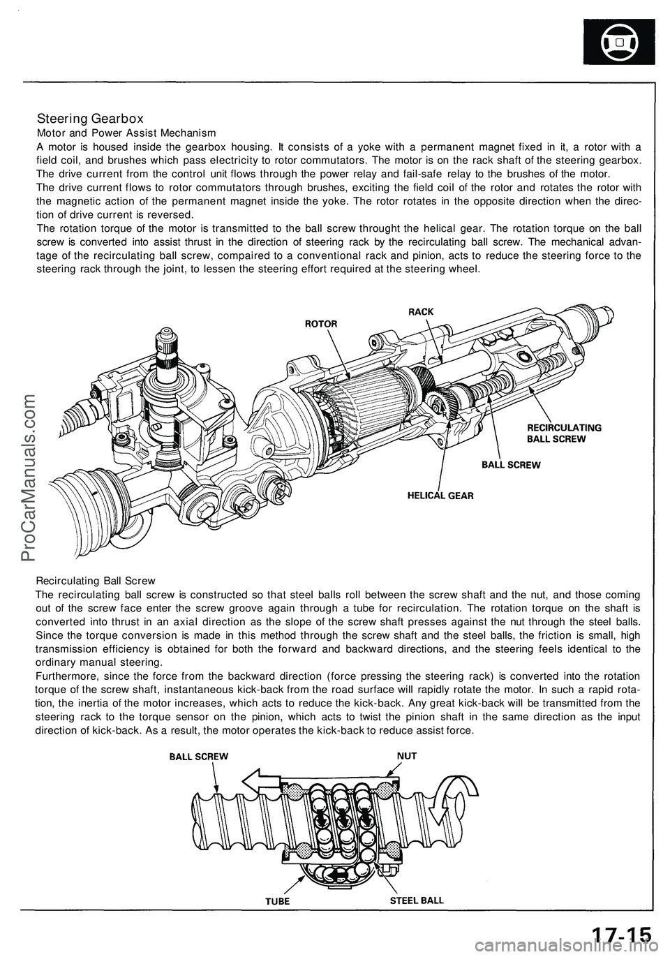
Steering Gearbox
Motor and Power Assist Mechanism
A motor is housed inside the gearbox housing. It consists of a yoke with a permanent magnet fixed in it, a rotor with a
field coil, and brushes which pass electricity to rotor commutators. The motor is on the rack shaft of the steering gearbox.
The drive current from the control unit flows through the power relay and fail-safe relay to the brushes of the motor.
The drive current flows to rotor commutators through brushes, exciting the field coil of the rotor and rotates the rotor with
the magnetic action of the permanent magnet inside the yoke. The rotor rotates in the opposite direction when the direc-
tion of drive current is reversed.
The rotation torque of the motor is transmitted to the ball screw throught the helical gear. The rotation torque on the ball
screw is converted into assist thrust in the direction of steering rack by the recirculating ball screw. The mechanical advan-
tage of the recirculating ball screw, compaired to a conventional rack and pinion, acts to reduce the steering force to the
steering rack through the joint, to lessen the steering effort required at the steering wheel.
Recirculating Ball Screw
The recirculating ball screw is constructed so that steel balls roll between the screw shaft and the nut, and those coming
out of the screw face enter the screw groove again through a tube for recirculation. The rotation torque on the shaft is
converted into thrust in an axial direction as the slope of the screw shaft presses against the nut through the steel balls.
Since the torque conversion is made in this method through the screw shaft and the steel balls, the friction is small, high
transmission efficiency is obtained for both the forward and backward directions, and the steering feels identical to the
ordinary manual steering.
Furthermore, since the force from the backward direction (force pressing the steering rack) is converted into the rotation
torque of the screw shaft, instantaneous kick-back from the road surface will rapidly rotate the motor. In such a rapid rota-
tion, the inertia of the motor increases, which acts to reduce the kick-back. Any great kick-back will be transmitted from the
steering rack to the torque sensor on the pinion, which acts to twist the pinion shaft in the same direction as the input
direction of kick-back. As a result, the motor operates the kick-back to reduce assist force.ProCarManuals.com
Page 994 of 1503

Tests
Brake Booster
Functional Test
1. With the engine stopped, depress the brake pedal
several times to deplete the vacuum reservoir, then
depress the pedal hard and hold it for 15 seconds. If
the pedal sinks, either the master cylinder is
bypassing internally, or the brake system (master
cylinder, lines, modulator, proportioning valve, or
calipers) is leaking.
2. Start the engine with the pedal depressed. If the
pedal sinks slightly, the vacuum booster is operat-
ing normally, if the pedal height does not vary, the
booster or check valve is faulty.
3. With the engine running, depress the brake pedal
lightly. Apply just enough pressure to hold back
automatic transmission creep. If the brake pedal
sinks more than 10 mm (3/8 in.) in three minutes,
the master cylinder is faulty. A slight change in
pedal height when the A/C compressor cycles on
and off if normal. (The A/C compressor load
changes the vacuum available to the booster.)
Leak Test
1. Depress the brake pedal with the engine running,
then stop the engine. If the pedal height does not
vary while depressed for 30 seconds, the vacuum
booster is OK. If the pedal rises, the booster is
faulty.
2. With the engine stopped, depress the brake pedal
several times using normal pressure. When the
pedal is first depressed, it should be low. On con-
secutive applications, the pedal height should grad-
ually rise. If the pedal position does not vary, check
the booster check valve.
Booster Check Valve Test
1. Disconnect the brake booster vacuum hose at the
booster or at the booster side of the valve.
2. Start the engine and let it idle. There should be vac-
uum. If no vacuum is available, the check valve is
not working properly. Replace the check valve and
retest.ProCarManuals.com
Page 1056 of 1503

Steering angl e senso r syste m chec k
1 . Star t th e engine .
2 . Pus h th e TC S switc h thre e time s withi n thre e seconds .
NOTE : Alway s maintai n th e sam e numbe r o f rota -
tions .
3 . Tur n th e steerin g whee l slowl y fro m lef t t o righ t mor e
tha n 1. 5 turns .
NOTE :
• Star t checkin g afte r th e steerin g whee l move s a t
leas t 1. 5 turn s fro m righ t t o left .
• Tur n th e steerin g whee l slowly , n o faste r tha n
on e tur n in fou r seconds .
4 . Pus h th e TC S switc h twic e withi n thre e seconds .
NOTE : Alway s maintai n th e sam e numbe r o f rota -
tions .
5 . Retur n th e steerin g whee l t o th e lef t sid e slowly , an d
chec k th e numbe r o f time s th e TC S indicato r ligh t
flashe s afte r th e whee l ha s move d approximatel y
on e turn .
NOTE :
• Star t th e chec k fro m th e beginnin g whe n th e steer -
in g whee l move s a t leas t on e tur n fro m lef t t o
right .
• Tur n th e steerin g whee l slowly , n o faste r tha n on e
tur n in fou r seconds .
Standar d numbe r o f time s th e TC S indicato r ligh t
flashes :
Manual Transmission : 5 time s
Automati c Transmission : 2 time s
6 . I f ther e is a n abnormality , chec k th e troubleshootin g
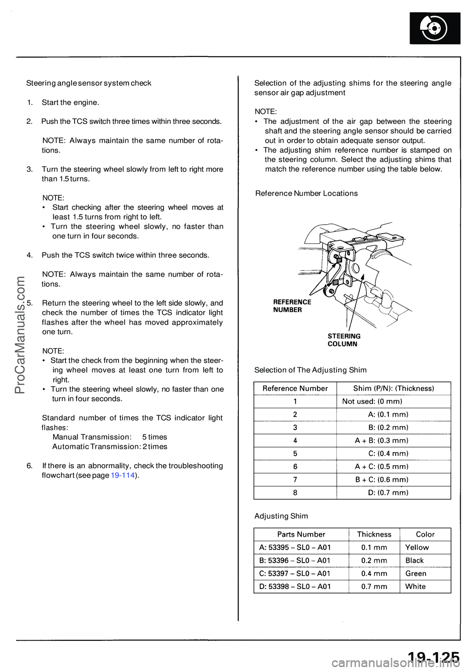
flowchar t (se e pag e 19-114 ). Selectio
n o f th e adjustin g shim s fo r th e steerin g angl e
senso r ai r ga p adjustmen t
NOTE:
• Th e adjustmen t o f th e ai r ga p betwee n th e steerin g
shaf t an d th e steerin g angl e senso r shoul d b e carrie d
ou t i n orde r t o obtai n adequat e senso r output .
• Th e adjustin g shi m referenc e numbe r i s stampe d o n
th e steerin g column . Selec t th e adjustin g shim s tha t
matc h th e referenc e numbe r usin g th e tabl e below .
Referenc e Numbe r Location s
Selectio n o f Th e Adjustin g Shi m
Adjustin g Shi m
ProCarManuals.com
Page 1237 of 1503
Relay and Control Unit Locations
Rear Bulkhead
PGM-FI MAIN RELAY
THROTTLE VALVE CONTROL
MOTOR RELAY
Wire colors: BLK,
YEL/BLK, GRN/RED,
and WHT/BLU
DASH LIGHTS
BRIGHTNESS
CONTROL UNIT
TRANSMISSION CONTROL
MODULE (TCM) (A/T)
PULSE UNIT (M/T)
ABS INDICATOR LIGHT
RELAY
Wire colors: BLU/WHT,
BLK, YEL/BLK, BLU/WHT
TCS CONTROL UNIT
FAN CONTROL
UNIT
ECMProCarManuals.com