Page 284 of 1503
Component Locatio n
Index
NOTE :
• I f a n intac t airba g assembl y ha s bee n remove d fro m a scrappe d ca r o r ha s bee n foun d defectiv e o r damage d durin g
transit , storag e o r service , i t shoul d b e deploye d (se e sectio n 23 ).
• Befor e removin g th e gearbox , remov e th e ignitio n ke y t o loc k th e steerin g shaf t fro m turning .
• Afte r installin g th e gearbox , chec k th e whee l alignmen t an d adjus t i f necessary .
STEERING WHEEL/AIRBA G ASSEMBL Y
Removal , pag e 17-43
Disassembly/Reassembly , pag e 17- 44
Installation , pag e 17-45
STEERIN G COLUM N
Removal , pag e 17-47
Inspection , pag e 17-49
Installation , pag e 17-50
STEERIN G GEARBO XRemoval/Installation , pag e 17-1 9
Disassembly , pag e 17-2 2
Inspection , pag e 17-2 1Reassembly , pag e 17-2 5
ProCarManuals.com
Page 369 of 1503

3-14
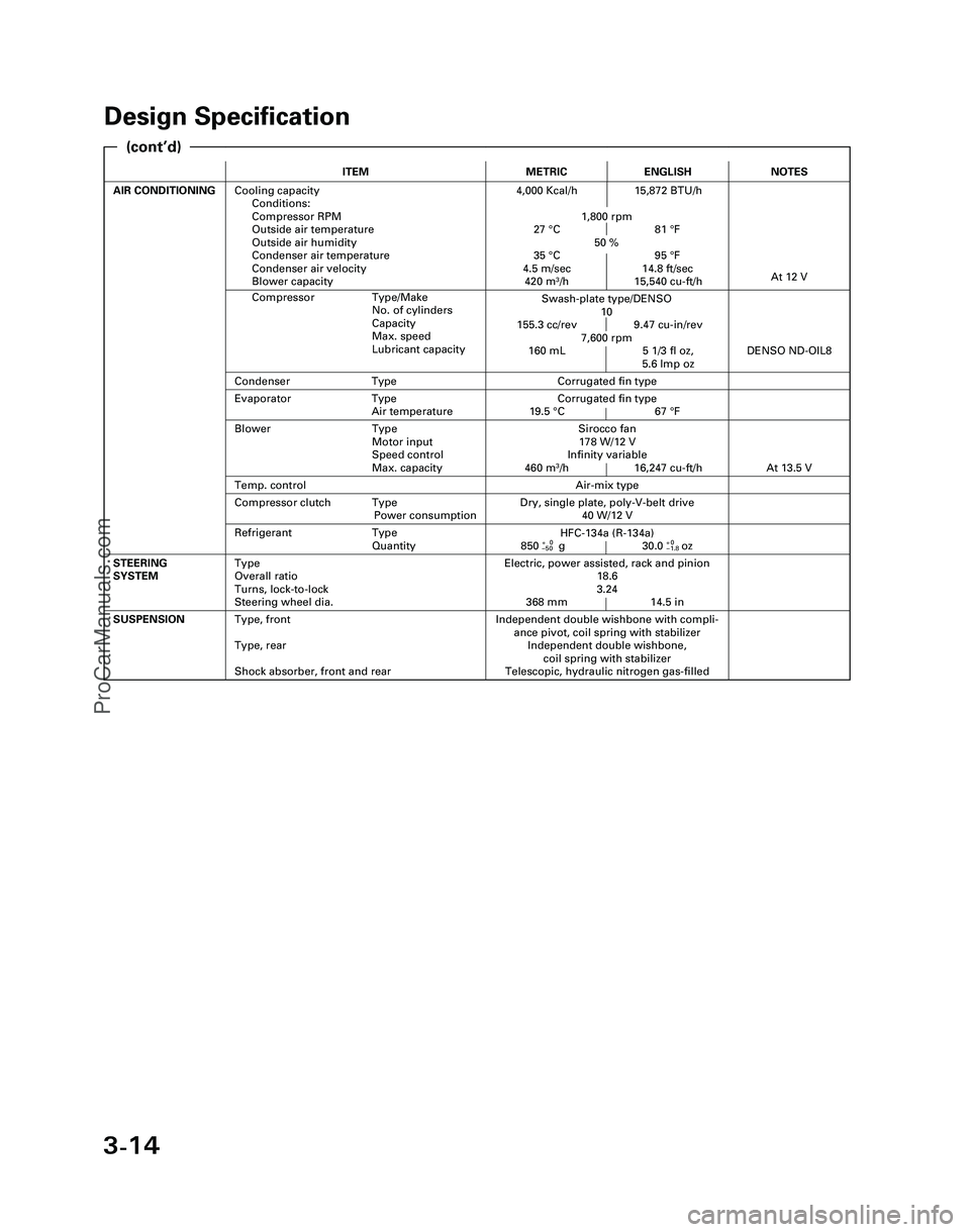
Design Specification
ITEMMETRICENGLISH
AIR CONDITIONINGCooling capacity
Conditions:
Compressor RPM
Outside air temperature
Outside air humidity
Condenser air temperature
Condenser air velocity
Blower capacity4,000 Kcal/h 15,872 BTU/h
1,800 rpm
27 °C 81 °F
50 %
35 °C 95 °F
4.5 m/sec 14.8 ft/sec
420 m
3/h 15,540 cu-ft/h
Independent double wishbone with compli-
ance pivot, coil spring with stabilizer
Independent double wishbone,
coil spring with stabilizer
Telescopic, hydraulic nitrogen gas-filledSUSPENSIONType, front
Type, rear
Shock absorber, front and rear
Evaporator Type
Air temperatureCorrugated fin type
19.5 °C 67 °F
Compressor Type/Make
No. of cylinders
Capacity
Max. speed
Lubricant capacity
NOTES
Swash-plate type/DENSO
10
155.3 cc/rev 9.47 cu-in/rev
7,600 rpm
160 mL 5 1/3 fl oz,
5.6 lmp oz
At 12 V
Air-mix type
Sirocco fan
178 W/12 V
Infinity variable
460 m
3/h 16,247 cu-ft/h
DENSO ND-OIL8
Condenser TypeCorrugated fin type
Temp. control
Blower Type
Motor input
Speed control
Max. capacity
At 13.5 V
Refrigerant Type
Quantity
Dry, single plate, poly-V-belt drive
40 W/12 VCompressor clutch Type
Power consumption
Electric, power assisted, rack and pinion
18.6
3.24
368 mm 14.5 inSTEERING
SYSTEMType
Overall ratio
Turns, lock-to-lock
Steering wheel dia.
HFC-134a (R-134a)
850+0g 30.0+0oz–50–1.8
(cont’d)
*04-NSX (61SW004)SEC03(01-16) 9/22/04 1:49 PM Page 3-14
ProCarManuals.com
Page 892 of 1503
Component Location s
Index
NOTE :
• I f a n intac t airba g assembl y ha s bee n remove d fro m a scrappe d vehicl e o r ha s bee n foun d defectiv e o r damage d durin g
transit , storag e o r service , i t shoul d b e deploye d (se e sectio n 24 ).
• Befor e removin g th e gearbox , remov e th e ignitio n ke y t o loc k th e steerin g shaft .
• Afte r installin g th e gearbox , chec k th e whee l alignmen t an d adjus t i f necessary .
STEERING GEARBO XRemoval/Installation , pag e 17-5 3
Illustrate d Index , pag e 17-5 7
Pinio n Preloa d Inspection , pag e 17-5 8
Rac k Guid e Scre w Adjustment , pag e 17-5 8
STEERIN
G COLUM N
Removal , pag e 17-4 7
Inspection , pag e 17-4 9
Installation , pag e 17-5 0
STEERIN G WHEEL /AIRBAG ASSEMBL YRemoval, pag e 17-4 3
Disassembly , pag e 17-4 4
Installation , pag e 17-4 5
EP
S CONTRO L UNI T
Replacement , pag e 17-62
ProCarManuals.com
Page 893 of 1503
System Description
Steering Column
The NSX/NSX-T has a tilt/telescopic steering column. The tilt/telescopic mechanism makes it possible to adjust the steer-
ing wheel in fore and aft, and up and down directions.
Tilt Mechanism
In the upper portion of the steering column is a joint on the steering shaft. This joint allows the steering wheel to be
adjusted
up or
down. When
the
tilt
lever
is
operated,
the
lock gears
are
detached
from
the
column
gear
to
release
the
lock.
The column moves upward or downward on two pivot bolts. When the tilt lever is returned to a fixed position after select-
ing the steering wheel height, the lock gear is engaged with the column gear to secure the column.ProCarManuals.com
Page 894 of 1503
Telescopic Mechanism
The upper steering shaft is divided into two shafts, connected by splines, making it possible for the shaft to telescope
while transmitting the rotation of the steering wheel. When the telescopic lever is lowered, the lever pivot turns in a direc-
tion to loosen the stop shim at the tip of the lever pivot, allowing the shaft to telescope. The telescopic stroke is limited by
the slot and stop on the movable shaft. After selecting a steering wheel position and locking the telescopic lever, the stop
shim presses, against the movable shaft, holding it in position.ProCarManuals.com
Page 898 of 1503

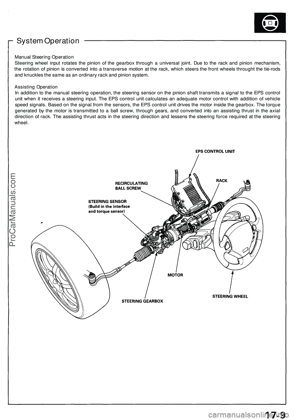
System Operatio n
Manual Steerin g Operatio n
Steerin g whee l inpu t rotate s th e pinio n o f th e gearbo x throug h a universa l joint . Du e t o th e rac k an d pinio n mechanism ,
th e rotatio n o f pinio n is converte d int o a transvers e motio n a t th e rack , whic h steer s th e fron t wheel s through t th e tie-rod s
an d knuckle s th e sam e a s a n ordinar y rac k an d pinio n system .
Assistin g Operatio n
In additio n t o th e manual steering operation , th e steerin g senso r o n th e pinio n shaf t transmit s a signa l t o th e EP S contro l
uni t whe n i t receive s a steerin g input . Th e EP S contro l uni t calculate s a n adequat e moto r contro l wit h additio n o f vehicl e
spee d signals . Base d o n th e signa l fro m th e sensors , th e EP S contro l uni t drive s th e moto r insid e th e gearbox . Th e torqu e
generate d b y th e moto r i s transmitte d t o a bal l screw , throug h gears , an d converte d int o a n assistin g thrus t i n th e axia l
directio n o f rack . Th e assistin g thrus t act s i n th e steerin g directio n an d lessen s th e steerin g forc e require d a t th e steerin g
wheel.
ProCarManuals.com
Page 899 of 1503

System Description
Function and Operation
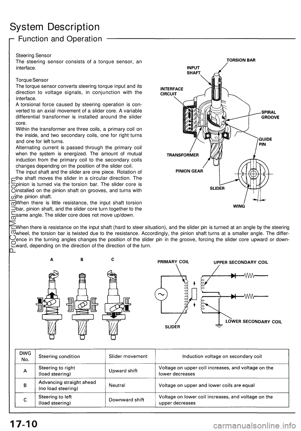
Steering Sensor
The steering sensor consists of a torque sensor, an
interface.
Torque Sensor
The torque sensor converts steering torque input and its
direction to voltage signals, in conjunction with the
interface.
A torsional force caused by steering operation is con-
verted to an axial movement of a slider core. A variable
differential transformer is installed around the slider
core.
Within the transformer are three coils, a primary coil on
the inside, and two secondary coils, one for right turns
and one for left turns.
Alternating current is passed through the primary coil
when the system is energized. The amount of mutual
induction from the primary coil to the secondary coils
changes depending on the position of the slider coil.
The input shaft and the slider are one piece. Rotation of
the shaft moves the slider in a circular direction. The
pinion is turned via the torsion bar. The slider core is
installed on the pinion shaft on grooves, and turns with
the pinion shaft.
When there is little resistance, the input shaft torsion
bar, pinion shaft, and the slider core turn together to the
same angle. The slider core does not move up/down.
When there is resistance on the input shaft (hard to steer situation), and the slider pin is turned at an angle by the steering
wheel, the torsion bar is twisted due to the resistance. Accordingly, the pinion shaft turns at a smaller angle. The differ-
ence in the turning angles changes the position of the slider pin in the groove, forcing the slider core upward or down-
ward, depending on the direction of the direction of the turn.ProCarManuals.com
Page 902 of 1503

Self-Diagnosis Function
The EPS control unit monitors the system inputs and outputs, and the driving current of the motor. If there is a problem in
the system, the control unit turns the system off by actuating the relay. Power assist stops and normal manual steering
operation resumes. The control unit also turns the EPS indicator light on to alert the driver, and memorizes the problem in
the form of a code. Connecting the terminals of the service check connector with the SCS service connector (special tool)
enables the EPS indicator light to blink the problem code when the ignition switch is turned on (II).
Unloader Control
If the steering wheel is turned fully and held in the full-lock position, the steering torque reaches the maximum point, and
an over-current flows to the motor. The control unit detects this and reduces the current flow to the motor.
Average Moving Current Control
The electric current flow to the motor is estimated from the current values detected by the current sensor, and the average
current is obtained at two second intervals. The motor driving current is suppressed when the average current value
exceeds a predetermined marginal value. The control unit regulates the motor current during continuous loading to sup-
press any excessive temperature rise in the motor.ProCarManuals.com