1997 ACURA NSX steering wheel
[x] Cancel search: steering wheelPage 904 of 1503
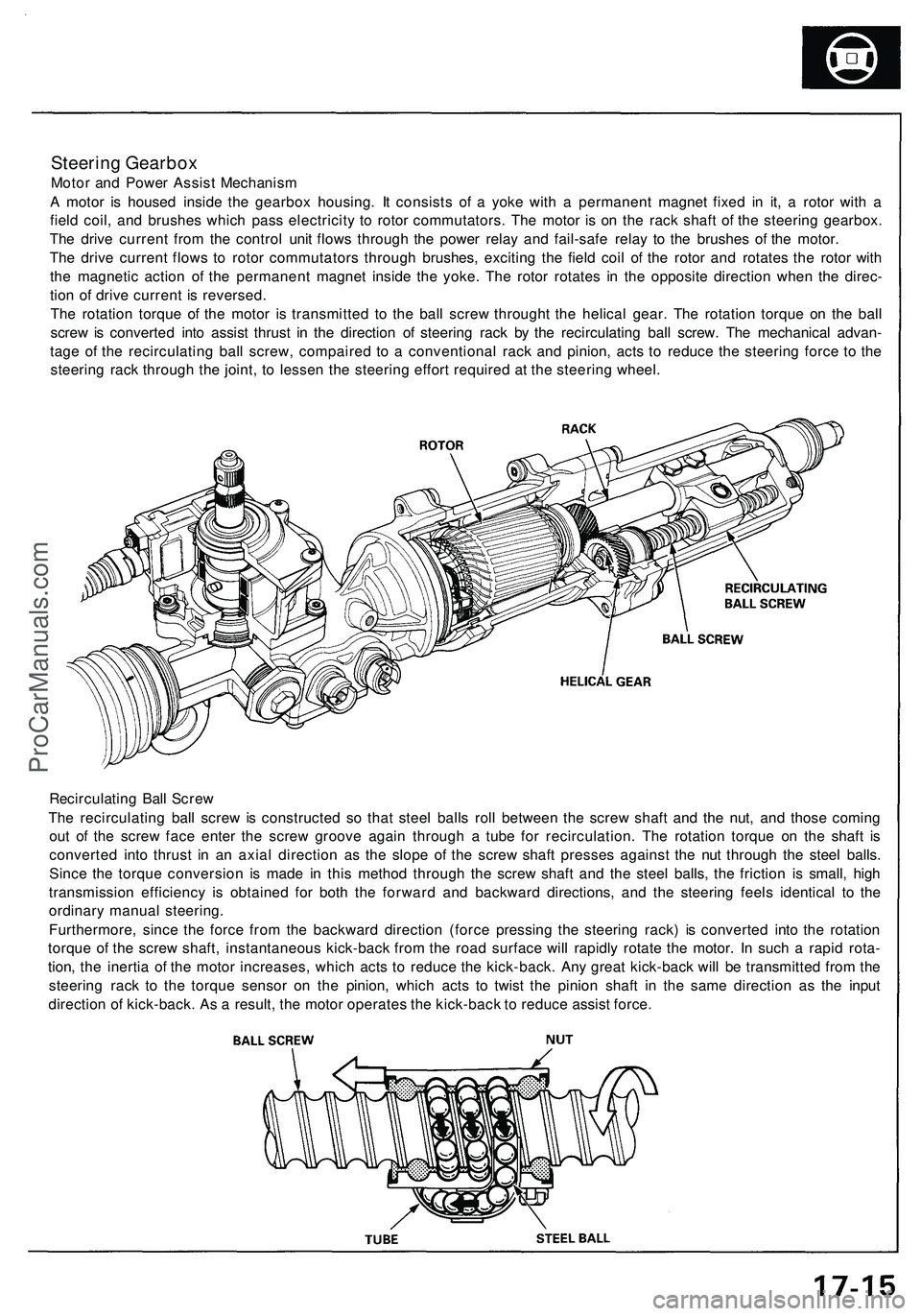
Steering Gearbox
Motor and Power Assist Mechanism
A motor is housed inside the gearbox housing. It consists of a yoke with a permanent magnet fixed in it, a rotor with a
field coil, and brushes which pass electricity to rotor commutators. The motor is on the rack shaft of the steering gearbox.
The drive current from the control unit flows through the power relay and fail-safe relay to the brushes of the motor.
The drive current flows to rotor commutators through brushes, exciting the field coil of the rotor and rotates the rotor with
the magnetic action of the permanent magnet inside the yoke. The rotor rotates in the opposite direction when the direc-
tion of drive current is reversed.
The rotation torque of the motor is transmitted to the ball screw throught the helical gear. The rotation torque on the ball
screw is converted into assist thrust in the direction of steering rack by the recirculating ball screw. The mechanical advan-
tage of the recirculating ball screw, compaired to a conventional rack and pinion, acts to reduce the steering force to the
steering rack through the joint, to lessen the steering effort required at the steering wheel.
Recirculating Ball Screw
The recirculating ball screw is constructed so that steel balls roll between the screw shaft and the nut, and those coming
out of the screw face enter the screw groove again through a tube for recirculation. The rotation torque on the shaft is
converted into thrust in an axial direction as the slope of the screw shaft presses against the nut through the steel balls.
Since the torque conversion is made in this method through the screw shaft and the steel balls, the friction is small, high
transmission efficiency is obtained for both the forward and backward directions, and the steering feels identical to the
ordinary manual steering.
Furthermore, since the force from the backward direction (force pressing the steering rack) is converted into the rotation
torque of the screw shaft, instantaneous kick-back from the road surface will rapidly rotate the motor. In such a rapid rota-
tion, the inertia of the motor increases, which acts to reduce the kick-back. Any great kick-back will be transmitted from the
steering rack to the torque sensor on the pinion, which acts to twist the pinion shaft in the same direction as the input
direction of kick-back. As a result, the motor operates the kick-back to reduce assist force.ProCarManuals.com
Page 913 of 1503
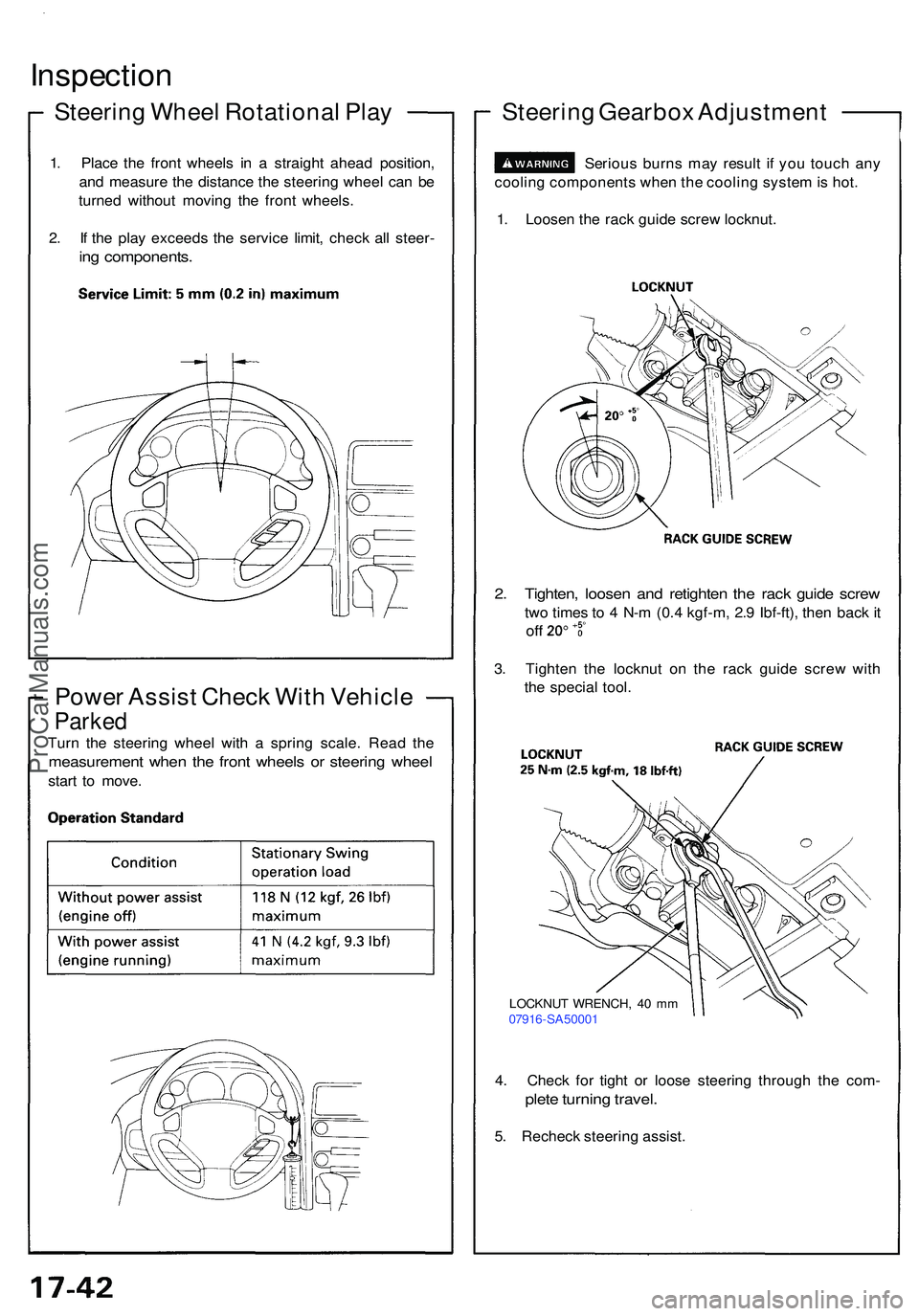
Inspection
Steering Whee l Rotationa l Pla y
1. Plac e th e fron t wheel s i n a straigh t ahea d position ,
an d measur e th e distanc e th e steerin g whee l ca n b e
turne d withou t movin g th e fron t wheels .
2 . I f th e pla y exceed s th e servic e limit , chec k al l steer -
ing components .
Power Assis t Chec k Wit h Vehicl e
Parked
Turn th e steerin g whee l wit h a sprin g scale . Rea d th e
measuremen t whe n th e fron t wheel s o r steerin g whee l
start t o move .
Steerin g Gearbo x Adjustmen t
1. Loose n th e rac k guid e scre w locknut .
Seriou
s burn s ma y resul t i f yo u touc h an y
coolin g component s whe n th e coolin g syste m is hot .
2. Tighten , loose n an d retighte n th e rac k guid e scre w
two time s t o 4 N- m (0. 4 kgf-m , 2. 9 Ibf-ft) , the n bac k i t
of f
3. Tighte n th e locknu t o n th e rac k guid e scre w wit h
th e specia l tool .
4 . Chec k fo r tigh t o r loos e steerin g throug h th e com -
plete turnin g travel .
5. Rechec k steerin g assist .
LOCKNU T WRENCH , 4 0 m m
0791 6-SA5000 1
ProCarManuals.com
Page 914 of 1503
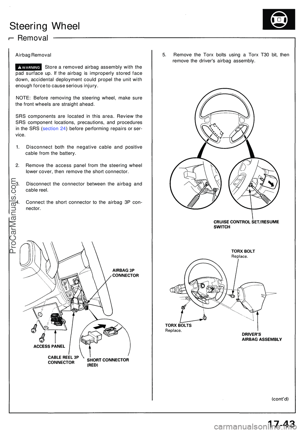
Steering Whee l
Remova l
Airbag Remova l
Stor e a remove d airba g assembl y wit h th e
pa d surfac e up . I f th e airba g i s improperl y store d fac e
down , accidenta l deploymen t coul d prope l th e uni t wit h
enoug h forc e to caus e seriou s injury .
NOTE : Befor e removin g th e steerin g wheel , mak e sur e
th e fron t wheel s ar e straigh t ahead .
SR S component s ar e locate d i n thi s area . Revie w th e
SR S componen t locations , precautions , an d procedure s
i n th e SR S ( sectio n 24 ) befor e performin g repair s o r ser -
vice .
1. Disconnec t bot h th e negativ e cabl e an d positiv e
cabl e fro m th e battery .
2 . Remov e th e acces s pane l fro m th e steerin g whee l
lowe r cover , the n remov e th e shor t connector .
3 . Disconnec t th e connecto r betwee n th e airba g an d
cabl e reel .
4 . Connec t th e shor t connecto r t o th e airba g 3 P con -
nector .
5. Remov e th e Tor x bolt s usin g a Tor x T3 0 bit , the n
remov e th e driver' s airba g assembly .
ProCarManuals.com
Page 915 of 1503
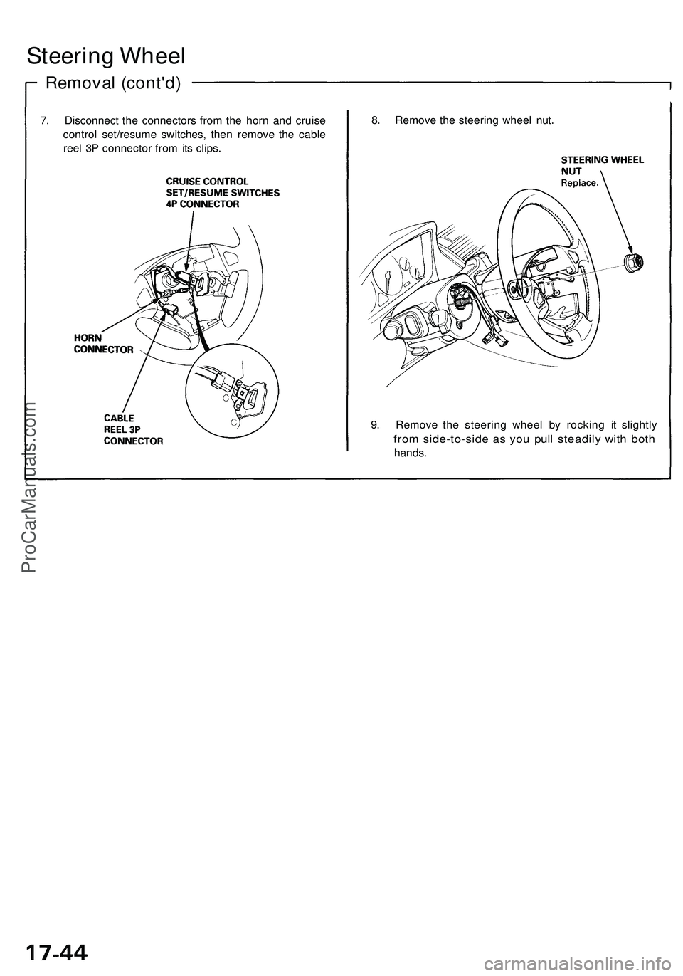
Steering Wheel
Removal (cont'd)
7. Disconnect the connectors from the horn and cruise
control set/resume switches, then remove the cable
reel 3P connector from its clips.
8. Remove the steering wheel nut.
9. Remove the steering wheel by rocking it slightly
from side-to-side as you pull steadily with both
hands.ProCarManuals.com
Page 917 of 1503
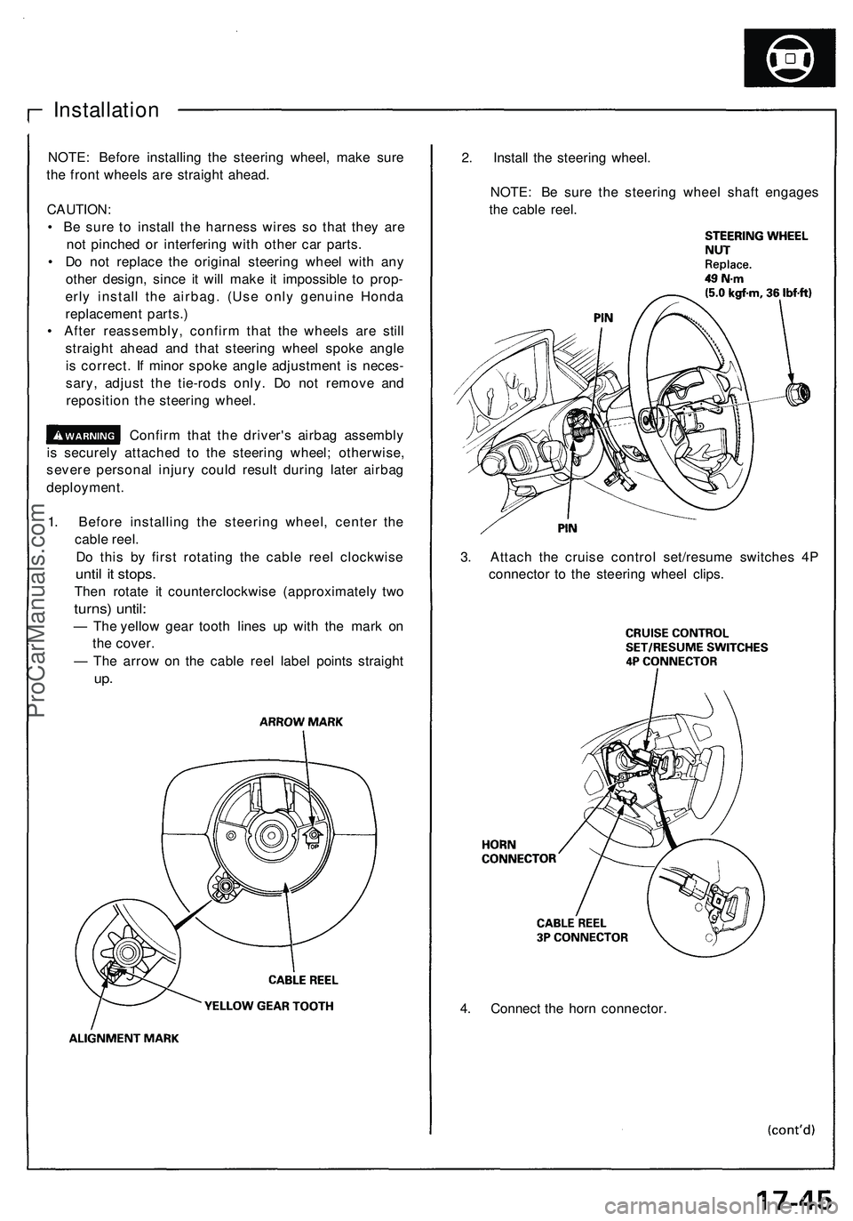
4. Connect the horn connector.
Installation
NOTE: Before installing the steering wheel, make sure
the front wheels are straight ahead.
CAUTION:
• Be sure to install the harness wires so that they are
not pinched or interfering with other car parts.
• Do not replace the original steering wheel with any
other design, since it will make it impossible to prop-
erly install the airbag. (Use only genuine Honda
replacement parts.)
• After reassembly, confirm that the wheels are still
straight ahead and that steering wheel spoke angle
is correct. If minor spoke angle adjustment is neces-
sary, adjust the tie-rods only. Do not remove and
reposition the steering wheel.
Confirm that the driver's airbag assembly
is securely attached to the steering wheel; otherwise,
severe personal injury could result during later airbag
deployment.
1. Before installing the steering wheel, center the
cable reel.
Do this by first rotating the cable reel clockwise
until it stops.
Then rotate it counterclockwise (approximately two
turns) until:
— The yellow gear tooth lines up with the mark on
the cover.
— The arrow on the cable reel label points straight
up.
2. Install the steering wheel.
NOTE: Be sure the steering wheel shaft engages
the cable reel.
3. Attach the cruise control set/resume switches 4P
connector to the steering wheel clips.ProCarManuals.com
Page 925 of 1503
Steering Gearbo x
Removal/Installatio n
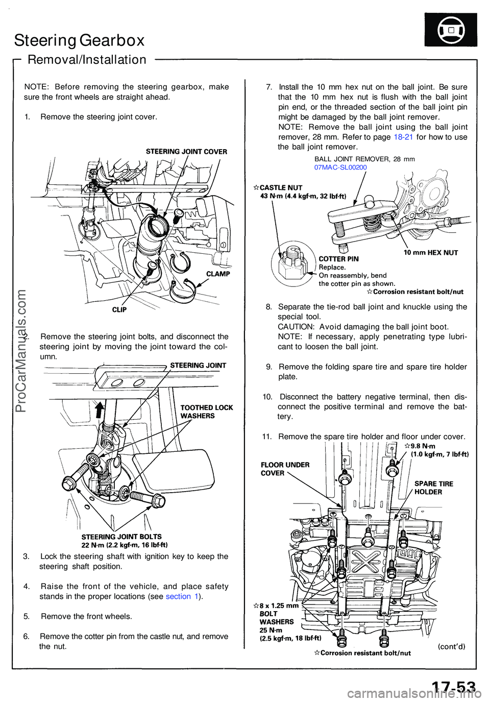
NOTE: Befor e removin g th e steerin g gearbox , mak e
sur e th e fron t wheel s ar e straigh t ahead .
1 . Remov e th e steerin g join t cover .
2 . Remov e th e steerin g join t bolts , an d disconnec t th e
steerin g join t b y movin g th e join t towar d th e col -
umn .
3. Loc k th e steerin g shaf t wit h ignitio n ke y t o kee p th e
steerin g shaf t position .
4 . Rais e th e fron t o f th e vehicle , an d plac e safet y
stand s in th e prope r location s (se e sectio n 1 ).
5 . Remov e th e fron t wheels .
6 . Remov e th e cotte r pi n fro m th e castl e nut , an d remov e
the nut .
7. Instal l th e 1 0 m m he x nu t o n th e bal l joint . B e sur e
tha t th e 1 0 m m he x nu t i s flus h wit h th e bal l join t
pi n end , o r th e threade d sectio n o f th e bal l join t pi n
migh t b e damage d b y th e bal l join t remover .
NOTE : Remov e th e bal l join t usin g th e bal l join t
remover , 2 8 mm . Refe r t o pag e 18-2 1 fo r ho w to us e
th e bal l join t remover .
BALL JOIN T REMOVER , 2 8 m m07MA C-SL0020 0
8. Separat e th e tie-ro d bal l join t an d knuckl e usin g th e
specia l tool .
CAUTION : Avoi d damagin g th e bal l join t boot .
NOTE : I f necessary , appl y penetratin g typ e lubri -
can t t o loose n th e bal l joint .
9 . Remov e th e foldin g spar e tir e an d spar e tir e holde r
plate .
10 . Disconnec t th e batter y negativ e terminal , the n dis -
connec t th e positiv e termina l an d remov e th e bat -
tery .
11 . Remov e th e spar e tir e holde r an d floo r unde r cover .
ProCarManuals.com
Page 1045 of 1503
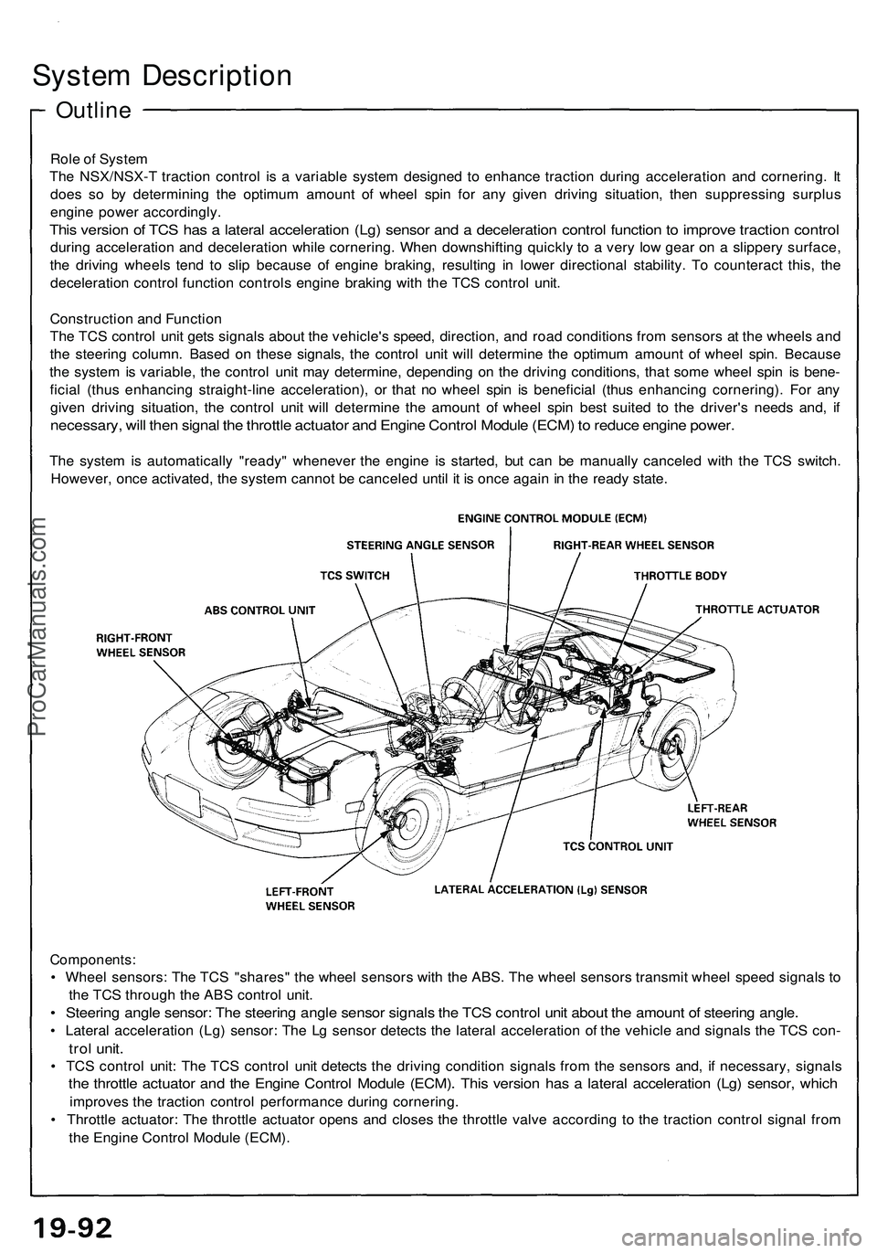
Outline
System Description
Role of System
The NSX/NSX-T traction control is a variable system designed to enhance traction during acceleration and cornering. It
does so by determining the optimum amount of wheel spin for any given driving situation, then suppressing surplus
engine power accordingly.
This version of TCS has a lateral acceleration (Lg) sensor and a deceleration control function to improve traction control
during acceleration and deceleration while cornering. When downshifting quickly to a very low gear on a slippery surface,
the driving wheels tend to slip because of engine braking, resulting in lower directional stability. To counteract this, the
deceleration control function controls engine braking with the TCS control unit.
Construction and Function
The TCS control unit gets signals about the vehicle's speed, direction, and road conditions from sensors at the wheels and
the steering column. Based on these signals, the control unit will determine the optimum amount of wheel spin. Because
the system is variable, the control unit may determine, depending on the driving conditions, that some wheel spin is bene-
ficial (thus enhancing straight-line acceleration), or that no wheel spin is beneficial (thus enhancing cornering). For any
given driving situation, the control unit will determine the amount of wheel spin best suited to the driver's needs and, if
necessary, will then signal the throttle actuator and Engine Control Module (ECM) to reduce engine power.
The system is automatically "ready" whenever the engine is started, but can be manually canceled with the TCS switch.
However, once activated, the system cannot be canceled until it is once again in the ready state.
Components:
• Wheel sensors: The TCS "shares" the wheel sensors with the ABS. The wheel sensors transmit wheel speed signals to
the TCS through the ABS control unit.
• Steering angle sensor: The steering angle sensor signals the TCS control unit about the amount of steering angle.
• Lateral acceleration (Lg) sensor: The Lg sensor detects the lateral acceleration of the vehicle and signals the TCS con-
trol unit.
• TCS control unit: The TCS control unit detects the driving condition signals from the sensors and, if necessary, signals
the throttle actuator and the Engine Control Module (ECM). This version has a lateral acceleration (Lg) sensor, which
improves the traction control performance during cornering.
• Throttle actuator: The throttle actuator opens and closes the throttle valve according to the traction control signal from
the Engine Control Module (ECM).ProCarManuals.com
Page 1046 of 1503
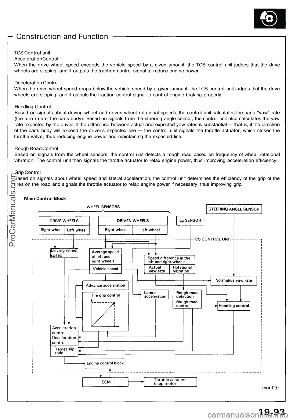
Construction and Function
TCS Control unit
Acceleration Control
When the drive wheel speed exceeds the vehicle speed by a given amount, the TCS control unit judges that the drive
wheels are slipping, and it outputs the traction control signal to reduce engine power.
Deceleration Control
When the drive wheel speed drops below the vehicle speed by a given amount, the TCS control unit judges that the drive
wheels are slipping, and it outputs the traction control signal to control engine braking properly.
Handling Control
Based on signals about driving wheel and driven wheel rotational speeds, the control unit calculates the car's "yaw" rate
(the turn rate of the car's body). Based on signals from the steering angle sensor, the control unit also calculates the yaw
rate expected by the driver. If the difference between actual and expected yaw rates is substantial —that is, if the direction
of the car's body will exceed the driver's expected line — the control unit signals the throttle actuator, which closes the
throttle valve, thus reducing engine power and maintaining the expected line.
Rough Road Control
Based on signals from the wheel sensors, the control unit detects a rough road based on frequency of wheel rotational
vibration. The control unit then signals the throttle actuator to relax engine power, thus improving acceleration efficiency.
Grip Control
Based on signals about wheel speed and lateral acceleration, the control unit determines the efficiency of the grip of the
tires on the road and signals the throttle actuator to relax engine power if necessary, thus improving grip.ProCarManuals.com