1997 ACURA NSX steering wheel
[x] Cancel search: steering wheelPage 1047 of 1503
Construction and Function (cont'd)
System Description
Fail-Safe Function
If the control unit detects an abnormality, it shuts the
traction control system off and causes the TCS indicator
light to come on. However if the abnormality is detected
while the TCS is activated, the control unit first estab-
lishes the appropriate wheel spin velocity, then shuts
the system down, thus preventing excessive wheel spin.
Self-Diagnosis Function
If the control unit detects an abnormality, it records a
Diagnostic Trouble Code (DTC) which can be used to
diagnose the problem. The DTC is shown at the TCS
indicator light when the Service Check connector termi-
nals are connected with the SCS service connector.
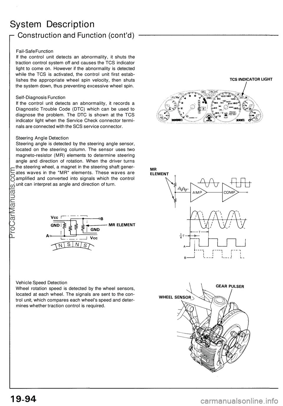
Steering Angle Detection
Steering angle is detected by the steering angle sensor,
located on the steering column. The sensor uses two
magneto-resistor (MR) elements to determine steering
angle and direction of rotation. When the driver turns
the steering wheel, a magnet in the steering shaft gener-
ates waves in the "MR" elements. These waves are
amplified and converted into signals which the control
unit can interpret as angle and direction of turn.
Vehicle Speed Detection
Wheel rotation speed is detected by the wheel sensors,
located at each wheel. The signals are sent to the con-
trol unit, which compares each wheel's speed and deter-
mines whether traction control is required.ProCarManuals.com
Page 1247 of 1503
Ignition Switch
Steering Lock Removal/Installation (cont'd)
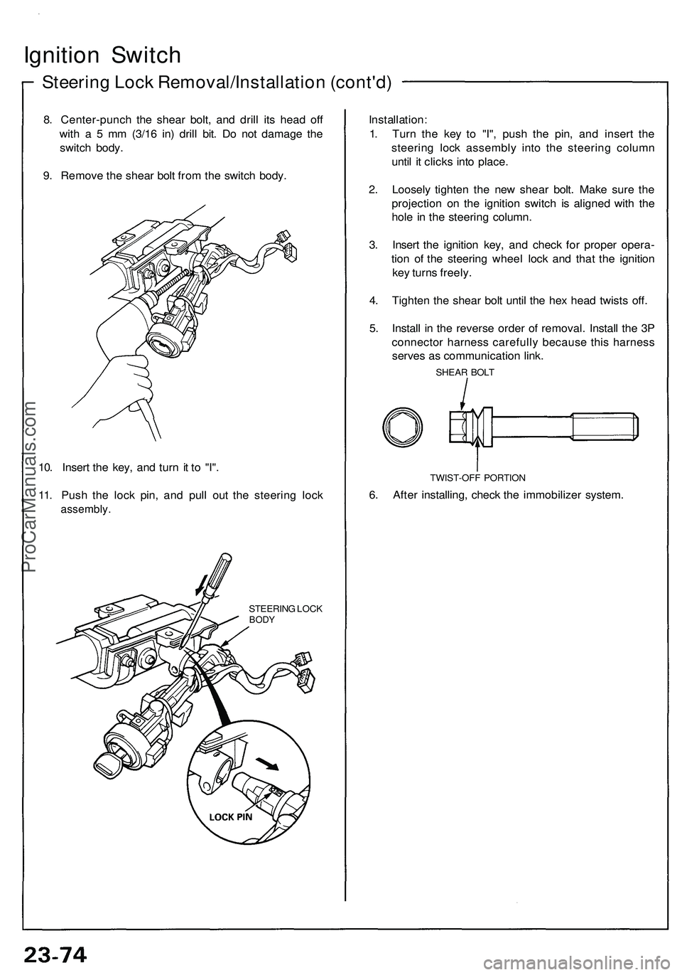
8. Center-punch the shear bolt, and drill its head off
with a 5 mm (3/16 in) drill bit. Do not damage the
switch body.
9. Remove the shear bolt from the switch body.
10. Insert the key, and turn it to "I".
11. Push the lock pin, and pull out the steering lock
assembly.
STEERING LOCK
BODY
Installation:
1. Turn the key to "I", push the pin, and insert the
steering lock assembly into the steering column
until it clicks into place.
2. Loosely tighten the new shear bolt. Make sure the
projection on the ignition switch is aligned with the
hole in the steering column.
3. Insert the ignition key, and check for proper opera-
tion of the steering wheel lock and that the ignition
key turns freely.
4. Tighten the shear bolt until the hex head twists off.
5. Install in the reverse order of removal. Install the 3P
connector harness carefully because this harness
serves as communication link.
SHEAR BOLT
TWIST-OFF PORTION
6. After installing, check the immobilizer system.ProCarManuals.com
Page 1477 of 1503
Supplemental Restraint System (SRS)
Steering-related Precautions
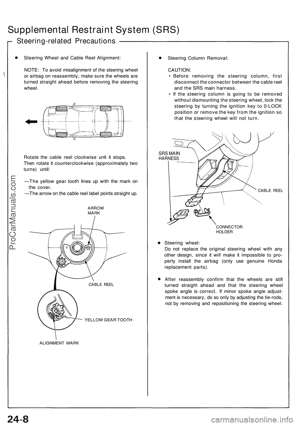
Steering Wheel and Cable Reel Alignment:
NOTE: To avoid misalignment of the steering wheel
or airbag on reassembly, make sure the wheels are
turned straight ahead before removing the steering
wheel.
Rotate the cable reel clockwise unit it stops.
Then rotate it counterclockwise (approximately two
turns) until:
—The yellow gear tooth lines up with the mark on
the cover.
—The arrow on the cable reel label points straight up.
ARROW
MARK
YELLOW GEAR TOOTH
ALIGNMENT MARK
Steering Column Removal:
CAUTION:
• Before removing the steering column, first
disconnect the connector between the cable reel
and the SRS main harness.
• If the steering column is going to be removed
without dismounting the steering wheel, lock the
steering by turning the ignition key to 0-LOCK
position or remove the key from the ignition so
that the steering wheel will not turn.
SRS MAIN
HARNESS
CABLE REEL
CONNECTOR
HOLDER
Steering wheel:
Do not replace the original steering wheel with any
other design, since it will make it impossible to pro-
perly install the airbag (only use genuine Honda
replacement parts).
After reassembly confirm that the wheels are still
turned straight ahead and that the steering wheel
spoke angle is correct. If minor spoke angle adjust-
ment is necessary, do so only by adjusting the tie-rods,
not by removing and repositioning the steering wheel.
CABLE REELProCarManuals.com
Page 1486 of 1503
Airbag Assembly Installation
CAUTION:
• Be sure to install the SRS wiring so that it is not pin-
ched or interfering with other car parts.
• Be sure the battery cables are disconnected.
• After completing repair work, be sure to remove the
short connectors (RED) and reconnect all the con-
nectors.
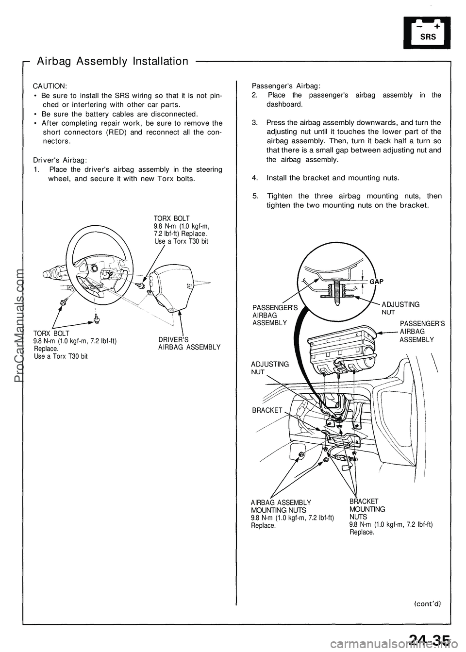
Driver's Airbag:
1. Place the driver's airbag assembly in the steering
wheel, and secure it with new Torx bolts.
TORX BOLT
9.8 N-m (1.0 kgf-m,
7.2 Ibf-ft) Replace.
Use a Torx T30 bit
TORX BOLT
9.8 N-m (1.0 kgf-m, 7.2 Ibf-ft)
Replace.
Use a Torx T30 bit
DRIVER'S
AIRBAG ASSEMBLY
Passenger's Airbag:
2. Place the passenger's airbag assembly in the
dashboard.
3. Press the airbag assembly downwards, and turn the
adjusting nut until it touches the lower part of the
airbag assembly. Then, turn it back half a turn so
that there is a small gap between adjusting nut and
the airbag assembly.
4. Install the bracket and mounting nuts.
5. Tighten the three airbag mounting nuts, then
tighten the two mounting nuts on the bracket.
PASSENGER'S
AIRBAG
ASSEMBLY
ADJUSTING
NUT
BRACKET
ADJUSTING
NUT
PASSENGER'S
AIRBAG
ASSEMBLY
AIRBAG ASSEMBLY
MOUNTING NUTS
9.8 N-m (1.0 kgf-m, 7.2 Ibf-ft)
Replace.
BRACKET
MOUNTING
NUTS
9.8 N-m (1.0 kgf-m, 7.2 Ibf-ft)
Replace.ProCarManuals.com
Page 1494 of 1503
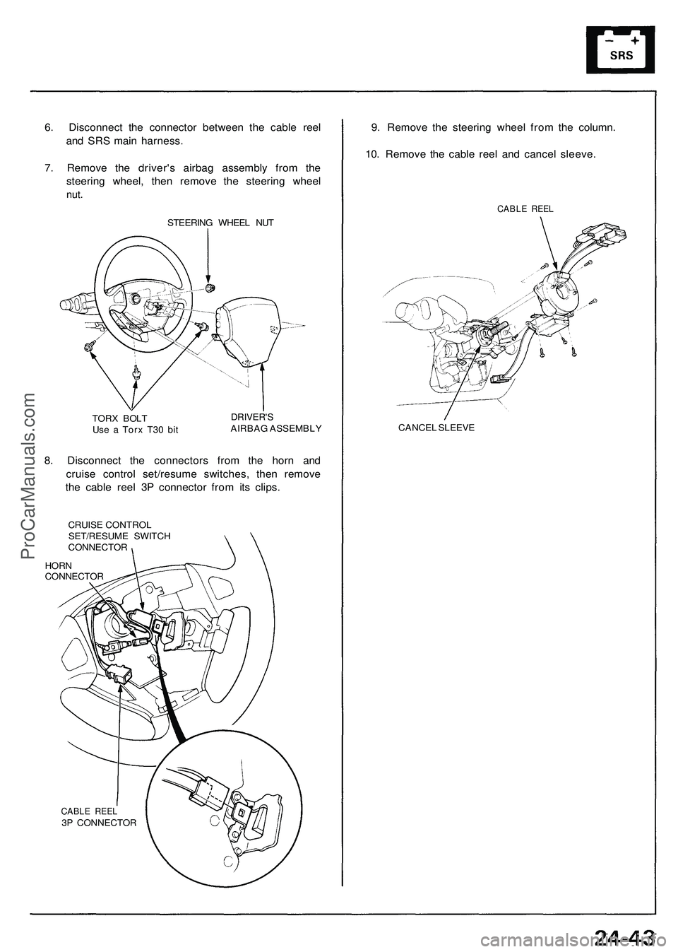
6. Disconnect the connector between the cable reel
and SRS main harness.
7. Remove the driver's airbag assembly from the
steering wheel, then remove the steering wheel
nut.
STEERING WHEEL NUT
TORX BOLT
Use a Torx T30 bit
DRIVER'S
AIRBAG ASSEMBLY
8. Disconnect the connectors from the horn and
cruise control set/resume switches, then remove
the cable reel 3P connector from its clips.
CRUISE CONTROL
SET/RESUME SWITCH
CONNECTOR
HORN
CONNECTOR
CABLE REEL
3P CONNECTOR
9. Remove the steering wheel from the column.
10. Remove the cable reel and cancel sleeve.
CABLE REEL
CANCEL SLEEVEProCarManuals.com
Page 1495 of 1503
Supplemental Restraint System (SRS)
Cable Reel Installation
CAUTION:
Before installing the steering wheel, the front wheels
should be aligned straight ahead.
Be sure to install the harness wires so that they are
not pinched or interfering with other car parts.
After reassembly, confirm that the wheels are still
turned straight ahead and that steering wheel spoke
angle is correct. If minor spoke angle adjustment is
necessary, do so only by adjusting the tie-rods, not
by removing and repositioning the steering wheel.
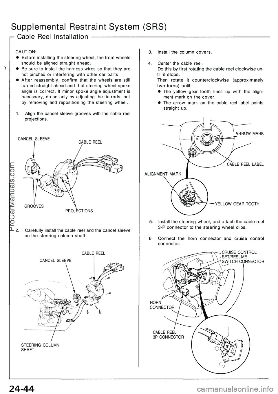
1. Align the cancel sleeve grooves with the cable reel
projections.
CANCEL SLEEVE
CABLE REEL
GROOVES
PROJECTIONS
2. Carefully install the cable reel and the cancel sleeve
on the steering column shaft.
CABLE REEL
CANCEL SLEEVE
STEERING COLUMN
SHAFT
3. Install the column covers.
4. Center the cable reel.
Do this by first rotating the cable reel clockwise un-
til it stops.
Then rotate it counterclockwise (approximately
two turns) until:
The yellow gear tooth lines up with the align-
ment mark on the cover.
The arrow mark on the cable reel label points
straight up.
ARROW MARK
CABLE REEL LABEL
ALIGNMENT MARK
YELLOW GEAR TOOTH
5. Install the steering wheel, and attach the cable reel
3-P connector to the steering wheel clips.
6. Connect the horn connector and cruise control
connector.
CRUISE CONTROL
SET/RESUME
SWITCH CONNECTOR
HORN
CONNECTOR
CABLE REEL
3P CONNECTORProCarManuals.com
Page 1496 of 1503
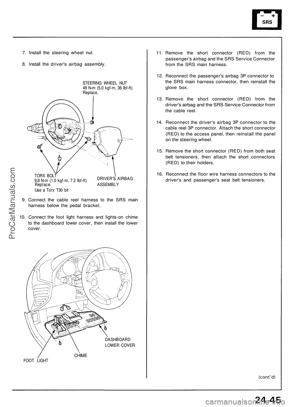
7. Instal l th e steerin g whee l nut .
8 . Instal l th e driver' s airba g assembly .
STEERING WHEE L NU T
4 9 N- m (5. 0 kgf-m , 3 6 Ibf-ft )
Replace .
DRIVER' S AIRBA G
TOR
X BOL T
9. 8 N- m (1. 0 kgf-m , 7. 2 Ibf-ft )
Replace . ASSEMBL Y
Us e a Tor x T3 0 bi t
9. Connec t th e cabl e ree l harnes s t o th e SR S mai n
harnes s belo w th e peda l bracket .
10 . Connec t th e foo t ligh t harnes s an d lights-o n chim e
t o th e dashboar d lowe r cover , the n instal l th e lowe r
cover .
DASHBOAR D
LOWE R COVE R
CHIMEFOOT LIGH T
11. Remov e th e shor t connecto r (RED ) fro m th e
passenger' s airba g an d th e SR S Servic e Connecto r
fro m th e SR S mai n harness .
1 2 . Reconnec t th e passenger' s airba g 3 P connecto r t o
th e SR S mai n harnes s connector , the n reinstal l th e
glov e box .
13 . Remov e th e shor t connecto r (RED ) fro m th e
driver' s airba g an d th e SR S Servic e Connecto r fro m
the cabl e reel .
14 . Reconnec t th e driver' s airba g 3 P connecto r t o th e
cabl e ree l 3 P connector . Attac h th e shor t connecto r
(RED ) t o th e acces s panel , the n reinstal l th e pane l
o n th e steerin g wheel .
15 . Remov e th e shor t connecto r (RED ) fro m bot h sea t
bel t tensioners , the n attac h th e shor t connector s
(RED ) t o thei r holders .
16 . Reconnec t th e floo r wir e harnes s connector s t o th e
driver' s an d passenger' s sea t bel t tensioners .
ProCarManuals.com
Page 1501 of 1503
Supplemental Restraint System (SRS)
SRS Unit Assembly Installation
CAUTION: Be sure to install the SRS wiring so that it is
not pinched or interfering with other car parts.
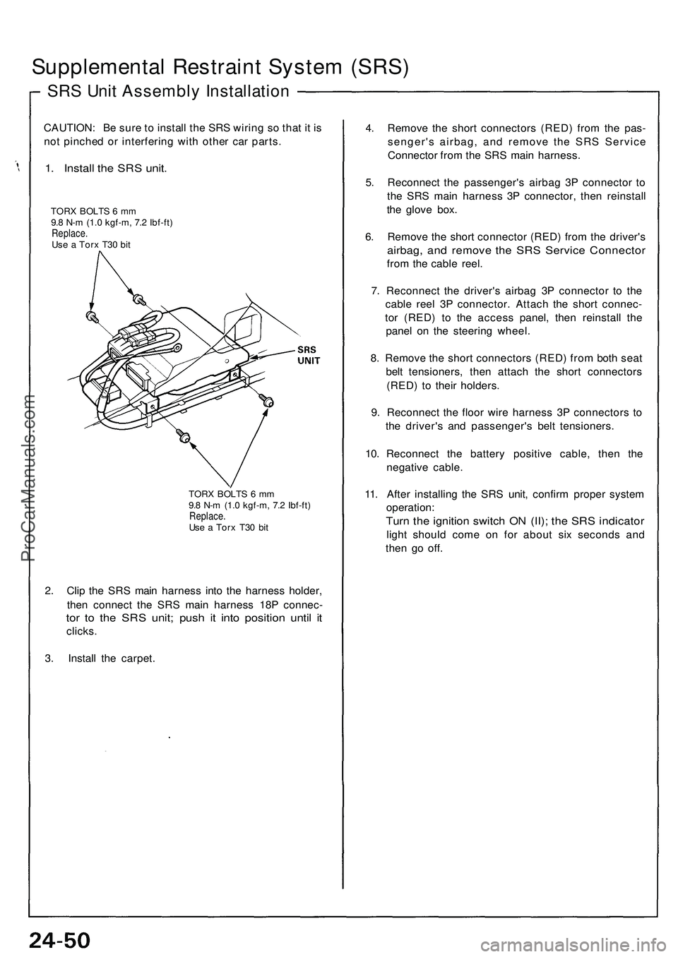
1. Install the SRS unit.
TORX BOLTS 6 mm
9.8 N-m (1.0 kgf-m, 7.2 Ibf-ft)
Replace.
Use a Torx T30 bit
TORX BOLTS 6 mm
9.8 N-m (1.0 kgf-m, 7.2 Ibf-ft)
Replace.
Use a Torx T30 bit
2. Clip the SRS main harness into the harness holder,
then connect the SRS main harness 18P connec-
tor to the SRS unit; push it into position until it
clicks.
3. Install the carpet.
4. Remove the short connectors (RED) from the pas-
senger's airbag, and remove the SRS Service
Connector from the SRS main harness.
5. Reconnect the passenger's airbag 3P connector to
the SRS main harness 3P connector, then reinstall
the glove box.
6. Remove the short connector (RED) from the driver's
airbag, and remove the SRS Service Connector
from the cable reel.
7. Reconnect the driver's airbag 3P connector to the
cable reel 3P connector. Attach the short connec-
tor (RED) to the access panel, then reinstall the
panel on the steering wheel.
8. Remove the short connectors (RED) from both seat
belt tensioners, then attach the short connectors
(RED) to their holders.
9. Reconnect the floor wire harness 3P connectors to
the driver's and passenger's belt tensioners.
10. Reconnect the battery positive cable, then the
negative cable.
11. After installing the SRS unit, confirm proper system
operation:
Turn the ignition switch ON (II); the SRS indicator
light should come on for about six seconds and
then go off.ProCarManuals.com