Page 543 of 1202
SF0X2-03
MF-18
- MFIINJECTOR
1996 TERCEL (RM440U)
REMOVAL
1. DISCONNECT VACUUM SEMSING HOSE FROM FUEL
PRESSURE REGULATOR
2. DISCONNECT FUEL RETURN HOSE FROM FUEL RE-
TURN PIPE
NOTICE:
Catch leaking in a container.
3. DISCONNECT FUEL INLET HOSE FROM DELIVERY
PIPE
(a) Disconnect the engine wire clamp from the No. 2 engine
hanger.
(b) Remove the union bolt, 2 gaskets and inlet hose.
4. DISCONNECT ENGINE WIRE
(a) Disconnect the engine wire from the surge tank stay.
(b) Disconnect the 4 injector connectors.
5. REMOVE DELIVERY PIPE WITH INJECTORS
(a) Remove the 2 bolts and delivery pipe together with the 4
injectors.
NOTICE:
Be careful not to drop the injectors when removing the de-
livery pipe.
(b) Pull out the 4 injectors from the delivery pipe.
(c) Remove the 2 spacers and 4 insulators from the cylinder
head.
(d) Remove the O-ring and grommet from each injector.
Page 547 of 1202

SF0X4-05
FI3271
New
O-Ring
New Grommet
P00159
CORRECT
WRONG
InjectorDelivery Pipe GrommetO-Ring
WRONG
P20295
Spacer
Insulator
Connector MF-22
- MFIINJECTOR
1996 TERCEL (RM440U)
INSTALLATION
1. INSTALL INJECTORS AND DELIVERY PIPE
(a) Install a new grommet to the injector.
(b) Apply a light coat of gasoline to an O-ring, and install it
to the injector.
(c) While turning the injector left and right, install it to the de-
livery pipe. Install the 4 injectors.
(d) Place the 2 spacers and 4 insulators in position on the cyl-
inder head.
(e) Place the injectors together with the delivery pipe on the
cylinder head.
(f) Check that the injectors rotate smoothly.
HINT:
If the injectors do not rotate smoothly, the probable cause is in-
correct installation of O-rings. Replace the O-rings.
(g) Position the injector connector upward.
(h) Install the 2 bolts.
Torque: 19 N´m (190 kgf´cm, 14 ft´lbf)
2. CONNECT ENGINE WIRE
(a) Connect the 4 injector connectors.
(b) Connect the engine wire to the surge tank stay.
3. CONNECT FUEL INLET HOSE TO DELIVERY PIPE
(a) Install 2 new gaskets and the inlet hose with the union
bolt.
Torque: 30 N´m (300 kgf´cm, 23 ft´lbf)
(b) Connect the engine wire clamp to the No.2 engine hang-
er.
4. CONNECT FUEL RETURN HOSE TO FUEL RETURN
PIPE
5. CONNECT VACUUM SENSING HOSE TO FUEL PRES-
SURE REGULATOR
Page 594 of 1202

CO18A-01
CO1242
Radiator Cap Tester
Radiator Cap
30° or More
- COOLINGRADIATOR
CO-13
1996 TERCEL (RM440U)
ON-VEHICLE INSPECTION
1. REMOVE RADIATOR CAP
CAUTION:
To avoid the danger of being burned, do not remove the ra-
diator cap while the engine and radiator are still hot, as fluid
and steam can be blown out under pressure.
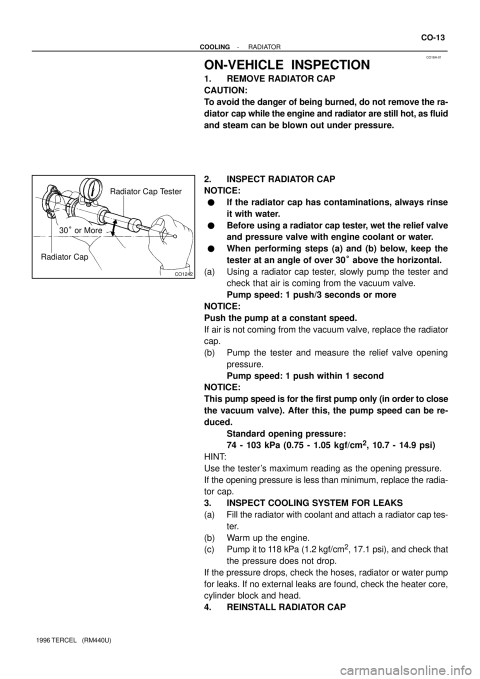
2. INSPECT RADIATOR CAP
NOTICE:
�If the radiator cap has contaminations, always rinse
it with water.
�Before using a radiator cap tester, wet the relief valve
and pressure valve with engine coolant or water.
�When performing steps (a) and (b) below, keep the
tester at an angle of over 30° above the horizontal.
(a) Using a radiator cap tester, slowly pump the tester and
check that air is coming from the vacuum valve.
Pump speed: 1 push/3 seconds or more
NOTICE:
Push the pump at a constant speed.
If air is not coming from the vacuum valve, replace the radiator
cap.
(b) Pump the tester and measure the relief valve opening
pressure.
Pump speed: 1 push within 1 second
NOTICE:
This pump speed is for the first pump only (in order to close
the vacuum valve). After this, the pump speed can be re-
duced.
Standard opening pressure:
74 - 103 kPa (0.75 - 1.05 kgf/cm
2, 10.7 - 14.9 psi)
HINT:
Use the tester's maximum reading as the opening pressure.
If the opening pressure is less than minimum, replace the radia-
tor cap.
3. INSPECT COOLING SYSTEM FOR LEAKS
(a) Fill the radiator with coolant and attach a radiator cap tes-
ter.
(b) Warm up the engine.
(c) Pump it to 118 kPa (1.2 kgf/cm
2, 17.1 psi), and check that
the pressure does not drop.
If the pressure drops, check the hoses, radiator or water pump
for leaks. If no external leaks are found, check the heater core,
cylinder block and head.
4. REINSTALL RADIATOR CAP
Page 639 of 1202
IG08G-03
S06147
- IGNITIONIGNITION COIL
IG-7
1996 TERCEL (RM440U)
REMOVAL
1. DISCONNECT HIGH-TENSION CORDS FROM IGNI-
TION COILS (See page IG-1)
2. REMOVE IGNITION COILS
(a) Disconnect the 2 connectors from the ignition coils.
(b) Remove the 2 bolts and 2 ignition coils from cylinder
head.
Torque: 8.5 N´m (85 kgf´cm, 70 in.´lbf)
HINT:
Arrange the ignition coils in correct order.
Page 717 of 1202

MX07F-04
Q06439
Z1891017 mm Head
Starter Set Bolt
Q06443
Q09187
Filler Plug
Oil Level
0 - 5 mm
Drain Plug MX-4
- MANUAL TRANSAXLEMANUAL TRANSAXLE UNIT
1996 TERCEL (RM440U)
REMOVAL
1. REMOVE BATTERY AND AIR CLEANER CASE AS-
SEMBLY WITH AIR HOSE
2. REMOVE CLUTCH RELEASE CYLINDER AND LINE
CLAMP
(a) Remove the 2 bolts and release cylinder.
(b) Remove the 2 bolts and release cylinder line clamp.
Torque: 12 N´m (120 kgf´cm, 9 ft´lbf)
3. DISCONNECT GROUND CABLE
Remove the 2 bolts and disconnect the 2 ground cables from
the transaxle side and engine left mounting bracket side.
4. DISCONNECT BACK-UP LIGHT SWITCH CONNEC-
TOR
5. DISCONNECT CONTROL CABLE
(a) Remove the 2 clips and washers.
(b) Remove the 2 clips from the cables.
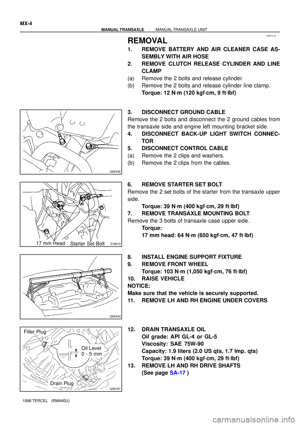
6. REMOVE STARTER SET BOLT
Remove the 2 set bolts of the starter from the transaxle upper
side.
Torque: 39 N´m (400 kgf´cm, 29 ft´lbf)
7. REMOVE TRANSAXLE MOUNTING BOLT
Remove the 3 bolts of transaxle case upper side.
Torque:
17 mm head: 64 N´m (650 kgf´cm, 47 ft´lbf)
8. INSTALL ENGINE SUPPORT FIXTURE
9. REMOVE FRONT WHEEL
Torque: 103 N´m (1,050 kgf´cm, 76 ft´lbf)
10. RAISE VEHICLE
NOTICE:
Make sure that the vehicle is securely supported.
11. REMOVE LH AND RH ENGINE UNDER COVERS
12. DRAIN TRANSAXLE OIL
Oil grade: API GL-4 or GL-5
Viscosity: SAE 75W-90
Capacity: 1.9 liters (2.0 US qts, 1.7 Imp. qts)
Torque: 39 N´m (400 kgf´cm, 29 ft´lbf)
13. REMOVE LH AND RH DRIVE SHAFTS
(See page SA-17)
Page 871 of 1202

BR0RM-04
F03521
SST
Gasket
N00744
SST
BR1728 BR0021
BR-18
- BRAKEBRAKE BOOSTER ASSEMBLY
1996 TERCEL (RM440U)
INSTALLATION
1. INSTALL BRAKE BOOSTER
(a) Install the booster and a new gasket.
(b) Install the clevis to the operating rod.
(c) Install and torque the booster installation nuts.
Torque: 14 N´m (145 kgf´cm, 10 ft´lbf)
(d) Insert the clevis pin into the clevis and brake pedal, and
install the clip to the clevis pin.
(e) Install the pedal return spring.
(f) Install the No.1 brake line clamp to the body.
(g) Install the No.2 brake line clamp to the body.
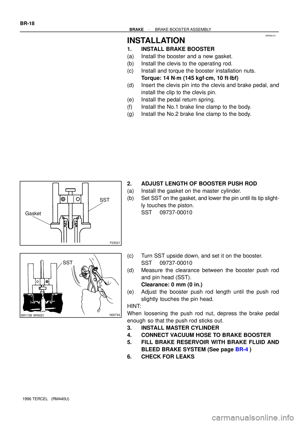
2. ADJUST LENGTH OF BOOSTER PUSH ROD
(a) Install the gasket on the master cylinder.
(b) Set SST on the gasket, and lower the pin until its tip slight-
ly touches the piston.
SST 09737-00010
(c) Turn SST upside down, and set it on the booster.
SST 09737-00010
(d) Measure the clearance between the booster push rod
and pin head (SST).
Clearance: 0 mm (0 in.)
(e) Adjust the booster push rod length until the push rod
slightly touches the pin head.
HINT:
When loosening the push rod nut, depress the brake pedal
enough so that the push rod sticks out.
3. INSTALL MASTER CYLINDER
4. CONNECT VACUUM HOSE TO BRAKE BOOSTER
5. FILL BRAKE RESERVOIR WITH BRAKE FLUID AND
BLEED BRAKE SYSTEM (See page BR-4)
6. CHECK FOR LEAKS